|
|
Expert
Posts: 1215
 
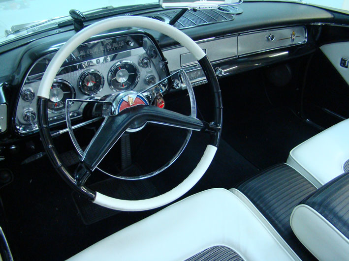
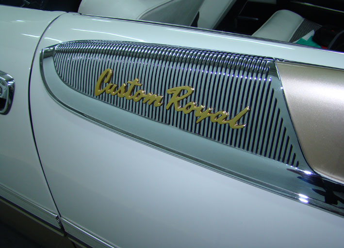
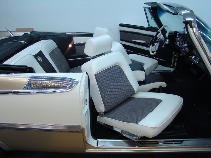
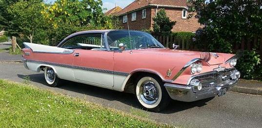
Location: SWITZERLAND | In this single thread I will give in steps some hints to get a nicer outfit of your car, as I did on my 1959 Dodge Custom Royal Lancer Convertible, useful also for other FWL-Cars (may-be already applied by others). Human Ladies look mostly more attractive when some personal features are accentuated. The same will happen with your car when restoring and invest a little effort (not money) in the outfit. First I present a general picture of the Interior.
 (DSC00156L.jpg) (DSC00156L.jpg)
Attachments
----------------
 DSC00156L.jpg (118KB - 839 downloads) DSC00156L.jpg (118KB - 839 downloads)
|
|
| |
|
Expert
Posts: 1215
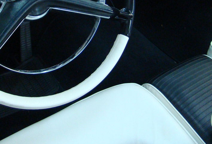
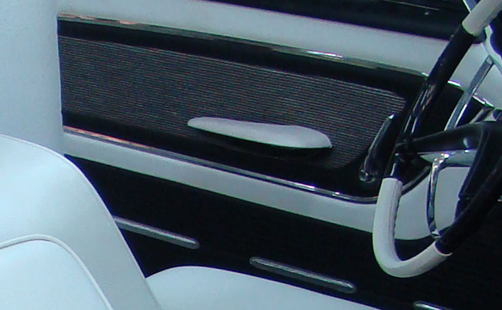
Location: SWITZERLAND | Steering Wheel: (this is also an answer to "Steering Wheel Restoration") The Steering Wheel is the "first" Interface to your car. It's mostly the first item you see when looking inside a car. Thus, the color should match the Interior, give a pleasant feeling when steering, look handsome and keep these attributes. Even with a broken Steering Wheel this can be acchieved easily. - Fill the broken parts with a two Component resine (the stability is given by the iron core). - take a rest of your Upholstery Material (or similar) and cover it with. You can bond with contact adhesive or cord it, the splice being in the rear side of the Stering Wheel (as shown in the picture).
 (DSC00156 Steering Wheel.jpg) (DSC00156 Steering Wheel.jpg)
Attachments
----------------
DSC00156 Steering Wheel.jpg (94KB - 814 downloads)
|
|
| |
|
Expert
Posts: 1215
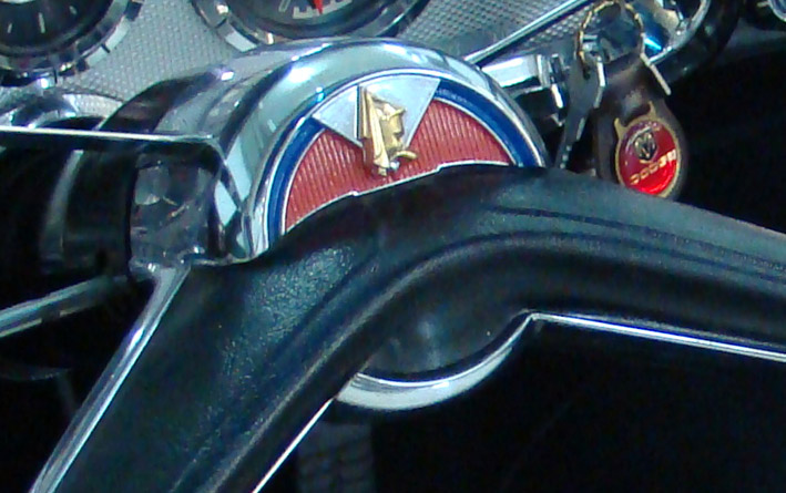
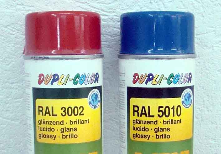
Location: SWITZERLAND | Horn Ring: Fill the cavities in black, other surfaces and items with the appropriate colors. For this and the emblems I used Standard Colors (RAL3002 / RAL5010) to have them available in the same tone at anytime. A Brillant Color keeps better dustfree. First I spray the Color in a small can and then apply it with a fine brush, and after some minutes clean arround with a solvent wetted cloth.
Edited by sermey 2008-12-19 1:31 PM
 (DSC00156 Horn Ring 1.jpg) (DSC00156 Horn Ring 1.jpg)
 (DSC00156 Horn Ring 2.jpg) (DSC00156 Horn Ring 2.jpg)
 (DSC01933 RAL Colors.jpg) (DSC01933 RAL Colors.jpg)
Attachments
----------------
DSC00156 Horn Ring 1.jpg (116KB - 877 downloads)
DSC00156 Horn Ring 2.jpg (114KB - 825 downloads)
DSC01933 RAL Colors.jpg (50KB - 858 downloads)
|
|
| |
|
Expert
Posts: 1215
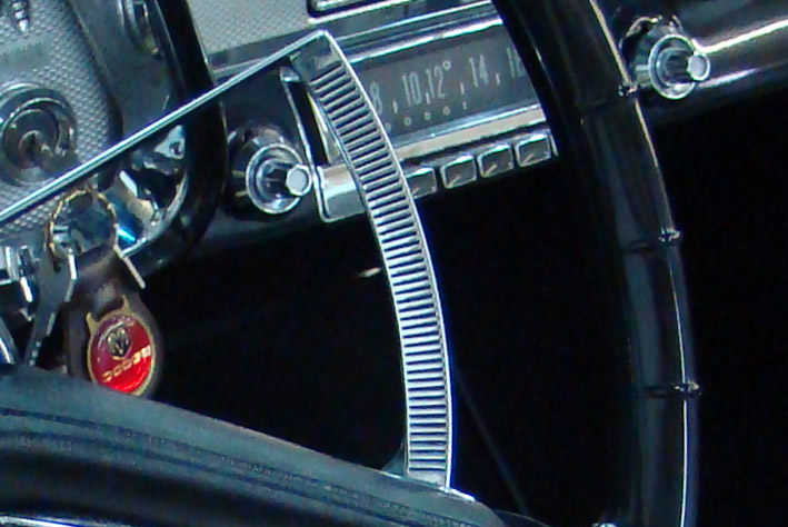
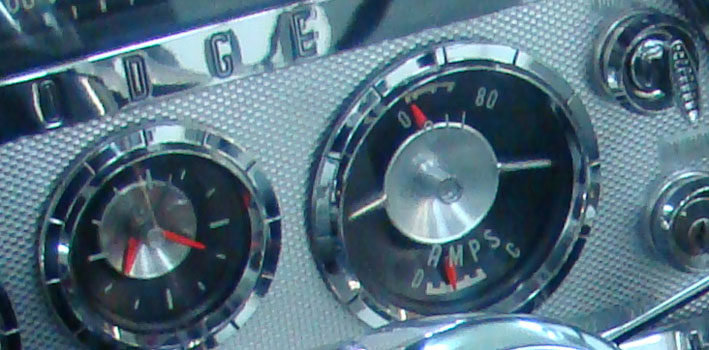
Location: SWITZERLAND | Gauges / Clock / Radio: The Needles of the Gauges and of the Radio got a bright Red applying NEON Fluorescent Color. Again, sprayed in a small can and using a small brush. Even at lower light the Needles are good visible.
Edited by sermey 2008-12-19 4:39 PM
 (DSC00156 Needles.jpg) (DSC00156 Needles.jpg)
 (DSC01935 Red NEON Color.jpg) (DSC01935 Red NEON Color.jpg)
Attachments
----------------
DSC00156 Needles.jpg (91KB - 841 downloads)
DSC01935 Red NEON Color.jpg (46KB - 829 downloads)
|
|
| |
|
Expert
Posts: 1215
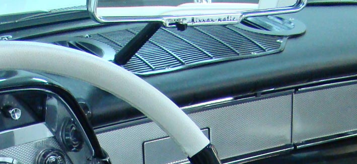
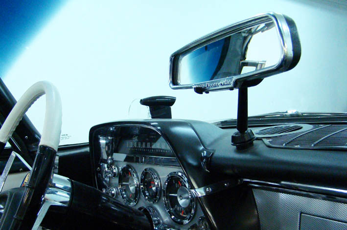
Location: SWITZERLAND | Mirror-Matic: No visible Cable from the Mirror-Matic to the Dashboard. Drill a duct inside the Stand (about 3.5mm) and use a high flexible isolated wire. (to know: Mirror-Matic is always ON. The OFF Switch just interrupts the Control Signal. I have a separate OFF Switch under the Dashboard to save Tube Life and Current)
 (DSC00156 Stand MirrorMatic.jpg) (DSC00156 Stand MirrorMatic.jpg)
Attachments
----------------
DSC00156 Stand MirrorMatic.jpg (70KB - 855 downloads)
|
|
| |
|
Expert
Posts: 1215
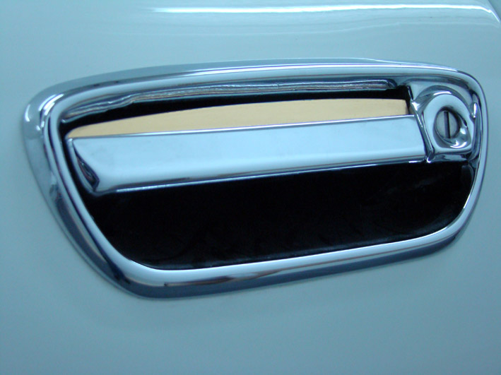
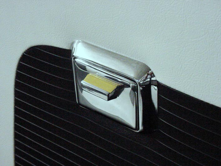
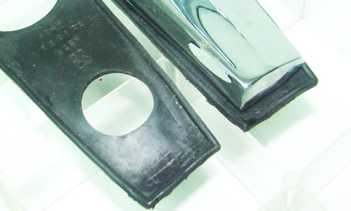
Location: SWITZERLAND | Door Handles: All black painted inside the Cavity until 1.5mm to the border. The upper face simply stick an adhesive Gold Foil (in Office Shop). The upper border can easily be cut after sticking by using a small blade. At this time I didn't had the Golden Coating, but on a plane surface this works excellent (already 10 years old!). Of course you may use your preferred Color.
 (DSC00028 Door Handles.jpg) (DSC00028 Door Handles.jpg)
Attachments
----------------
DSC00028 Door Handles.jpg (88KB - 868 downloads)
|
|
| |
|

Board Moderator & Exner Expert 10K+
Posts: 13062
  
Location: Southern Sweden - Sturkö island | The Mirrormatic shall be connected to the H terminal on the light switch Serge - that means that it's only on when you run with the lights on. |
|
| |
|
Expert
Posts: 1215
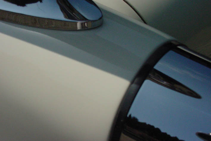
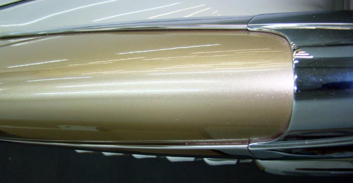
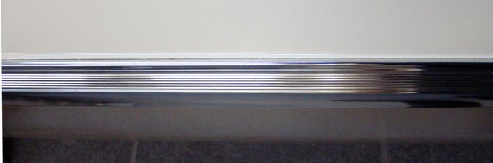
Location: SWITZERLAND | Side Mouldings: Again, filled with Brillant Black Color.
 (DSC00026 Side Moulding 1.jpg) (DSC00026 Side Moulding 1.jpg)
 (DSC00026 Side Moulding 2.jpg) (DSC00026 Side Moulding 2.jpg)
Attachments
----------------
DSC00026 Side Moulding 1.jpg (96KB - 838 downloads)
DSC00026 Side Moulding 2.jpg (98KB - 851 downloads)
|
|
| |
|
Expert
Posts: 1215
Location: SWITZERLAND | Swen answered:The Mirrormatic shall be connected to the H terminal on the light switch Serge - that means that it's only on when you run with the lights on. That's correct. May-be my Current-Source is still from there. But at lights ON the Tube is always ON even when not using.
|
|
| |
|
Board Moderator & Exner Expert 10K+
Posts: 13062
Location: Southern Sweden - Sturkö island | That correct Serge - then in many countries dipped beam during daytime is a must, so you've got a point with your extra switch!
I like your styling tips - I can see many discrete applications also on the '60 Chryslers. |
|
| |
|
Expert
Posts: 1215
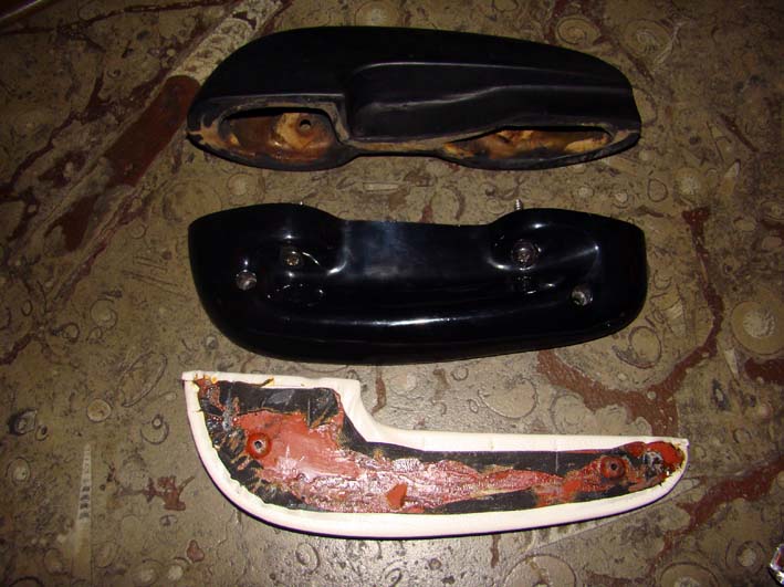
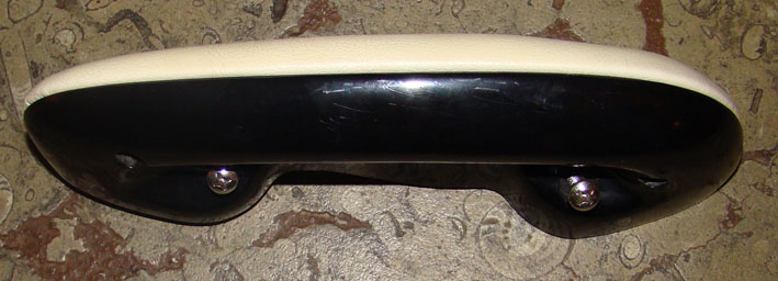
Location: SWITZERLAND | Arm Rests: Originally the Arm Rests have been black and I coated them accordingly. Later I found white with the same Upholstery Material looks "gentler" and I coated them again over the black coating (see picture). The problem is that the coating has to go around curves and corners. I applied on both sides Contact Glue. Usually must wait till dry and then apply. In this case put enough Contact Glue and then put directly together. Now the coating getting softer you can move, stretch and pull the coating around the corners removing all plyings. Then fix all around with Masking Tape and let it be for a week. Recently I purchased in eBay a pair of Arm Rests in black as "Original Reserve". I couldn't see on the Pics and I didn't know, this was an older, one piece Arm Rest in Rubber Material. This ones cannot be coated partially without seeing the abrupt cut. The all unicolor, white or another color, gives a harmonic impression of the Interior. The Arm Rests, the Steering Wheel, as the Door Panels, and when a Convertible also the Top Cover, all contribute to an outstanding Outfit.
Edited by sermey 2008-12-19 6:26 PM
 (DSC00154 Arm Rests 1.jpg) (DSC00154 Arm Rests 1.jpg)
 (DSC00154 Arm Rest 2.jpg) (DSC00154 Arm Rest 2.jpg)
 (DSC01941 Arm Rest.jpg) (DSC01941 Arm Rest.jpg)
 (DSC01945L.jpg) (DSC01945L.jpg)
Attachments
----------------
DSC00154 Arm Rests 1.jpg (98KB - 838 downloads)
DSC00154 Arm Rest 2.jpg (75KB - 862 downloads)
DSC01941 Arm Rest.jpg (82KB - 816 downloads)
DSC01945L.jpg (61KB - 823 downloads)
|
|
| |
|
Expert
Posts: 1215
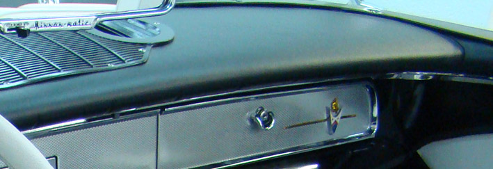
Location: SWITZERLAND | Dashboard: My Dashboard was broken and hardened, due to age and exposure to sun. There was no chance to repair it, neither I found a source for a replacement. As the Arm Rests, I coated all the surface in black directly on the Metal after removing all the previous stuff. So, it will never brake again. I did a tool to burn in the designed lines, without satisfying results. I know this is not correct, but done perfectly and the best I could do at this time. Today there are best repros available in Sweden. Can just say: my solution is for free!
Edited by sermey 2008-12-20 3:50 AM
 (DSC00156 Dashboard.jpg) (DSC00156 Dashboard.jpg)
Attachments
----------------
DSC00156 Dashboard.jpg (75KB - 849 downloads)
|
|
| |
|
Expert
Posts: 1215
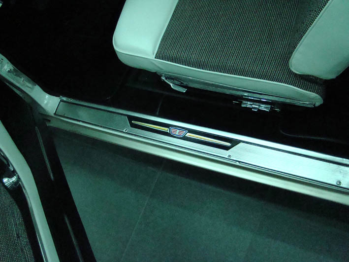
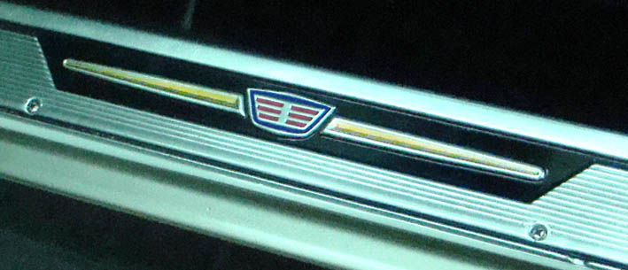
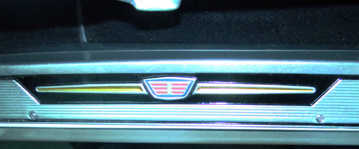
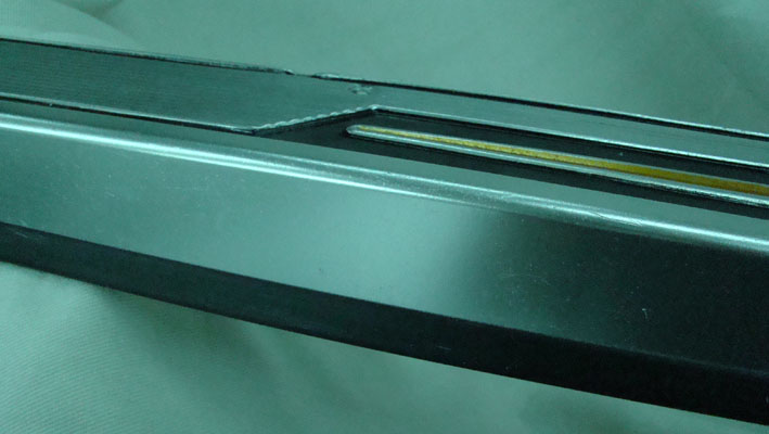
Location: SWITZERLAND | Sill Plates: A Make-Up on the Sill Plates accentuates the Emblems and gives an added Value to this items, using the same Colors as already used. But first the Sill Plates have to be metal-brushed and galvanic anodized (elox). On the inner Side I pushed up a Profile, available in Office Shops and beeing used for binding or hanging big Pictures, available in lenght of 1m and in different colors, here in black to get a straight and rounded edge. Today there are very nice Reproductions available in Sweden, at the time not disposable. As far I saw not painted.
Can say again: This way is for free and looks nice!
Edited by sermey 2008-12-20 7:03 AM
 (DSC01946 Sill Plate 1.jpg) (DSC01946 Sill Plate 1.jpg)
 (DSC01946 Sill Plate 2.jpg) (DSC01946 Sill Plate 2.jpg)
 (DSC01949 Inner Border.jpg) (DSC01949 Inner Border.jpg)
 (DSC01952 View Inside.jpg) (DSC01952 View Inside.jpg)
Attachments
----------------
DSC01946 Sill Plate 1.jpg (81KB - 885 downloads)
DSC01946 Sill Plate 2.jpg (60KB - 936 downloads)
DSC01949 Inner Border.jpg (70KB - 869 downloads)
DSC01952 View Inside.jpg (59KB - 860 downloads)
|
|
| |
|
Board Moderator & Exner Expert 10K+
Posts: 13062
Location: Southern Sweden - Sturkö island | Lots of nice tips without spending a fortune, thanks for sharing Serge! |
|
| |
|
Elite Veteran
Posts: 781

Location: Montreal, Canada | sermey - 2008-12-20 6:44 AM
Sill Plates: Today there are very nice Reproductions available in Sweden, at the time not disposable. As far I saw not painted.
Where can we get them? Do they make them for sedan models?
Any web site? |
|
| |
|
Expert
Posts: 1215
Location: SWITZERLAND | catman asked: Where can we get them? Do they make them for sedan models? Kent in Sweden (des5859) is dealing wth this parts and can answer your question.
|
|
| |
|
Expert
Posts: 1215
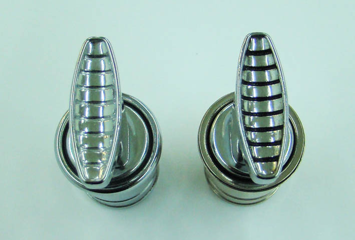
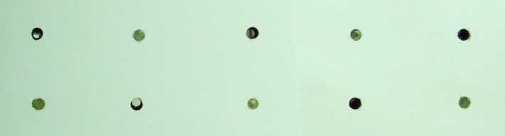
Location: SWITZERLAND | Knobs: Black Shadow on Panel Knobs. Here the optical difference shown on two Lighters (my second Spare Part). Also nice on round Knobs, outside around.
Edited by sermey 2008-12-24 5:46 PM
 (DSC02019LL.jpg) (DSC02019LL.jpg)
Attachments
----------------
DSC02019LL.jpg (61KB - 889 downloads)
|
|
| |
|
Expert
Posts: 1215
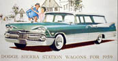
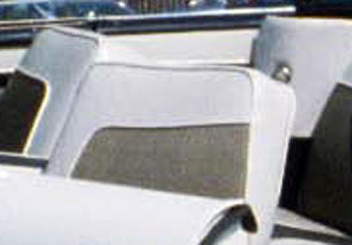
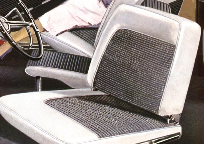
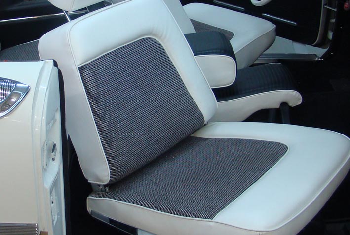
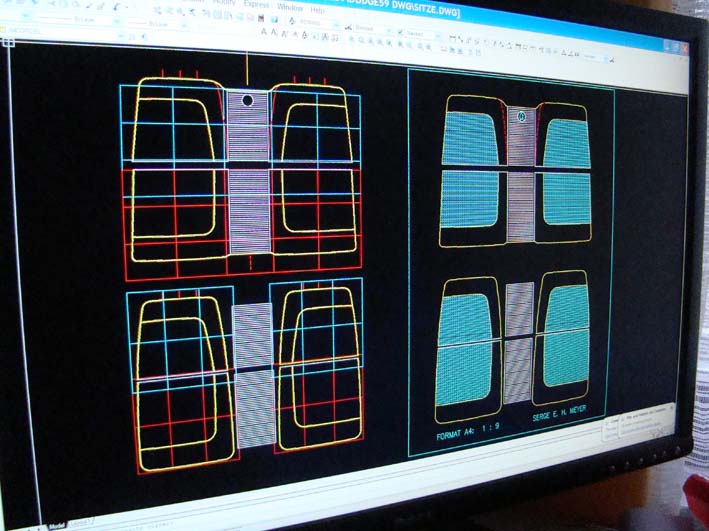
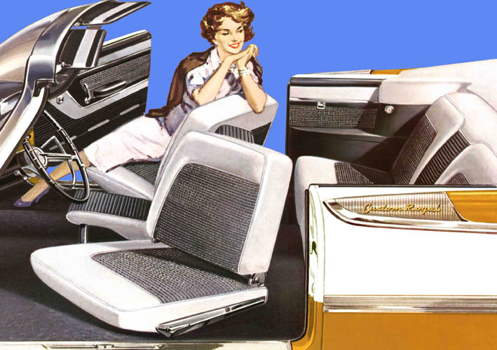
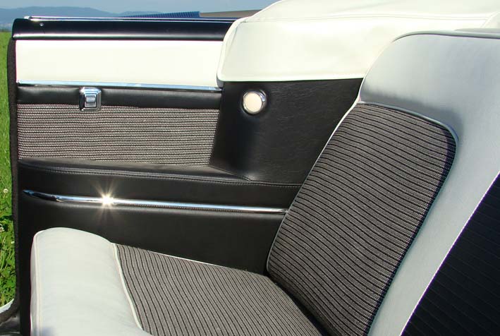
Location: SWITZERLAND | Upholstery: I don't know if my Upholtery of my car was Original. It looked, as many other Interiors, as "hooked bags". I took the Promotional Picture (Convertible with Swivel Seats) and designed it accordingly in CAD for the "upholstery Man" telling him, I wanted a good visible feed in, as in the promotional picture. He did a perfect Job and now it's like original. This coulds also be done with any pre-manufactured Upholsteries. See at the diffference!
Edited by sermey 2008-12-25 5:41 AM
 (Uphosltery old.jpg) (Uphosltery old.jpg)
 (OR Upholstery 2.jpg) (OR Upholstery 2.jpg)
 (DSC00154Upholstery 3.jpg) (DSC00154Upholstery 3.jpg)
 (DSC02021 Upholstery DesignL .jpg) (DSC02021 Upholstery DesignL .jpg)
 (2008-04-27 SM Interior copy.jpg) (2008-04-27 SM Interior copy.jpg)
 (DSC00210 Rear Seats L.jpg) (DSC00210 Rear Seats L.jpg)
Attachments
----------------
Uphosltery old.jpg (39KB - 932 downloads)
OR Upholstery 2.jpg (94KB - 897 downloads)
DSC00154Upholstery 3.jpg (83KB - 872 downloads)
DSC02021 Upholstery DesignL .jpg (90KB - 919 downloads)
2008-04-27 SM Interior copy.jpg (94KB - 905 downloads)
DSC00210 Rear Seats L.jpg (82KB - 971 downloads)
|
|
| |
|

Expert
Posts: 1302
Location: Skaneateles,NY(summer)/Port St.Lucie,FL(winter) | Absolutely STUNNING car!... |
|
| |
|

Expert
Posts: 1444
Location: Oconomowoc Wi | Is your CAD available to others for the Custom Royal interior ? ...and does that also include the inner / door pannels. Your car is outstanding. |
|
| |
|
Expert
Posts: 1215
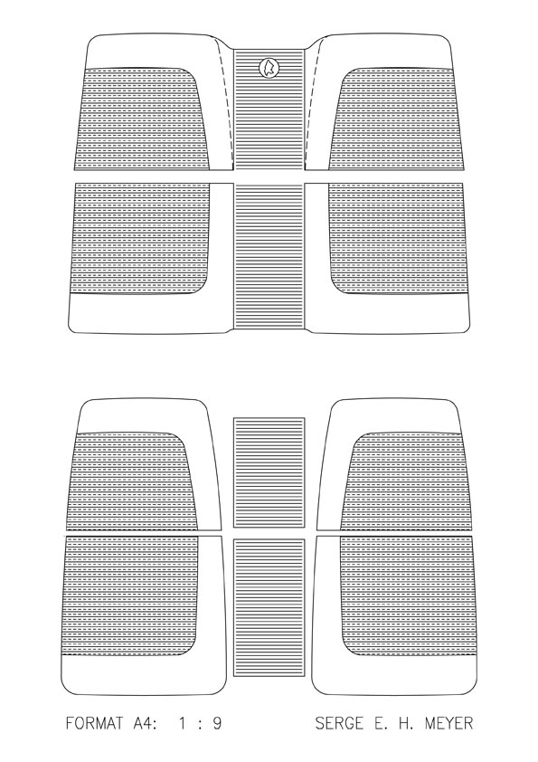
Location: SWITZERLAND | Bart_59_Dodge - 2008-12-25 3:07 PM Is your CAD available to others for the Custom Royal interior ? ...and does that also include the inner / door pannels. Your car is outstanding. Bart, I put it here for you and all the other Dodge 59 Owners of FLK.Net. It was not an easy Job to get this from Original Promotional Pictures. Just make a zoomed Printout of the PDF-File, and you have the exact countours as used for my Upholstery. I didn't made any door panels, I furnished the original ones with comments. As you can see on the upper picture taken from the PC-Display: Having only a A4-Plotter at this time (10 years ago), I divided the layout in many A4- Sheets and then stuck them together to get the Original size in one (about 10 A4-sheets per Seat).
- SERGE -
Edited by sermey 2008-12-25 1:11 PM
 (Dodge 59 Upholstery L.jpg) (Dodge 59 Upholstery L.jpg)
Attachments
----------------
Dodge 59 Upholstery L.jpg (114KB - 933 downloads)
Dodge 59 Upholstery.pdf (41KB - 916 downloads)
|
|
| |
|
Expert
Posts: 1444
Location: Oconomowoc Wi | Serge,
Is there any chance you have the CAD in a DWG or similar format ?
I have autocad and other CAD software at work available to me.
I could probably open up the file in its native format. It would be more functional as well. |
|
| |
|
Expert
Posts: 1215
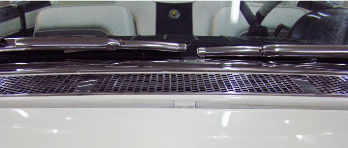
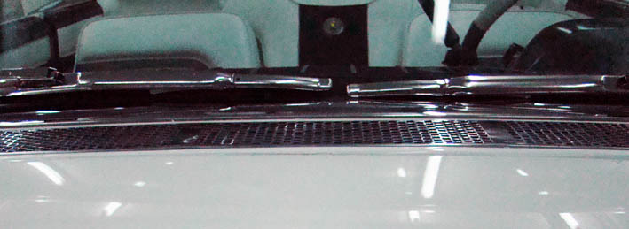
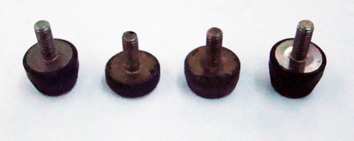
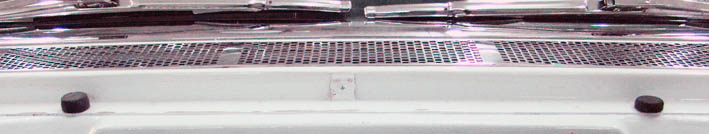
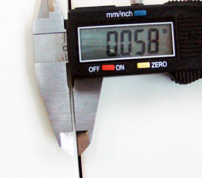
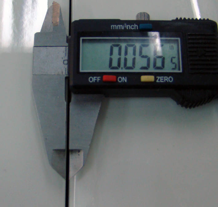
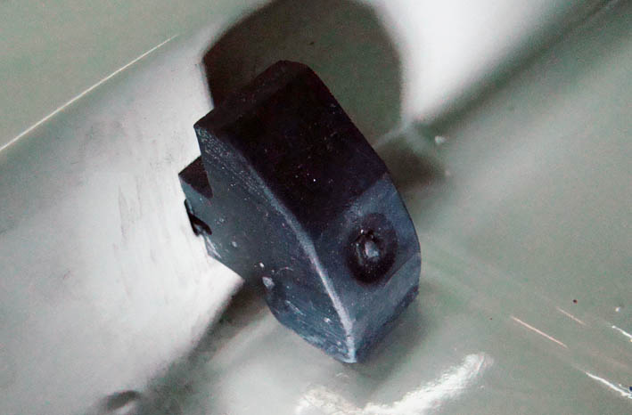
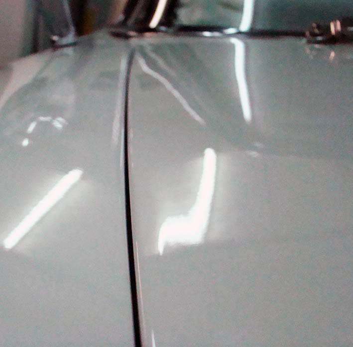
Location: SWITZERLAND | Hood: Correctly centering the Hood without damaging the Edges was a big issue, the disposable gap on my car beeing about only 0.06* for each side. A solution for a precise and durable positioning was needed. On the rear end, the Hood was too low, when correctly adjusted at the corners. I mounted 4 rubber bumpers, modified to the needed height, left and right corner one, the other two according the picture. Now the edge from one corner to the other is and stay parallel in height. On each side of the Hood I put a Round-Head Screw, adjusting the height for exact centering with washers. To assure a good and tight fixing the original centering rubber should be squeezed as shown in the picture. Now the Hood is exact centered all around, no cracked edges and no vibrations of the hood - a perfect fitting even at very small gaps.
Edited by sermey 2008-12-25 2:04 PM
 (DSC02023L Hood rear before.jpg) (DSC02023L Hood rear before.jpg)
 (DSC02037L Hood rear after.jpg) (DSC02037L Hood rear after.jpg)
 (DSC02036L Positioner Hood Rear.jpg) (DSC02036L Positioner Hood Rear.jpg)
 (DSC02038L Center Positioners.jpg) (DSC02038L Center Positioners.jpg)
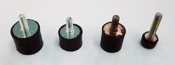 (DSC02040L Positioner Sizes.jpg) (DSC02040L Positioner Sizes.jpg)
 (DSC02024l Hood Gap Left.jpg) (DSC02024l Hood Gap Left.jpg)
 (DSC02025L Hood Gap Right.jpg) (DSC02025L Hood Gap Right.jpg)
 (DSC02033L Positioner Left.jpg) (DSC02033L Positioner Left.jpg)
 (DSC02032L Hood Rubber Left.jpg) (DSC02032L Hood Rubber Left.jpg)
 (DSC02042L Final Result.jpg) (DSC02042L Final Result.jpg)
Attachments
----------------
DSC02023L Hood rear before.jpg (54KB - 861 downloads)
DSC02037L Hood rear after.jpg (48KB - 871 downloads)
DSC02036L Positioner Hood Rear.jpg (37KB - 917 downloads)
DSC02038L Center Positioners.jpg (36KB - 882 downloads)
DSC02040L Positioner Sizes.jpg (36KB - 897 downloads)
DSC02024l Hood Gap Left.jpg (65KB - 1000 downloads)
DSC02025L Hood Gap Right.jpg (54KB - 845 downloads)
DSC02033L Positioner Left.jpg (60KB - 858 downloads)
DSC02032L Hood Rubber Left.jpg (53KB - 865 downloads)
DSC02042L Final Result.jpg (62KB - 868 downloads)
|
|
| |
|
Expert
Posts: 1215
Location: SWITZERLAND | sermey - 2008-12-19 10:07 PM Mirror-Matic: No visible Cable from the Mirror-Matic to the Dashboard. Drill a duct inside the Stand (about 3.5mm) and use a high flexible isolated wire. (to know: Mirror-Matic is always ON. The OFF Switch just interrupts the Control Signal. I have a separate OFF Switch under the Dashboard to save Tube Life and Current)
Another View of the Stand. Is this Mount / Foot as Original?
 (DSC02022L Stand Mirror-Matic.jpg) (DSC02022L Stand Mirror-Matic.jpg)
Attachments
----------------
DSC02022L Stand Mirror-Matic.jpg (78KB - 854 downloads)
|
|
| |
|
Expert
Posts: 1215
Location: SWITZERLAND | catman - 2008-12-20 11:37 PM sermey - 2008-12-20 6:44 AM Sill Plates: Today there are very nice Reproductions available in Sweden, at the time not disposable. As far I saw not painted.
Where can we get them? Do they make them for sedan models? Any web site? I just spoke to Jan Fridberg in Sweden. He manufactures Dual Air Cleaners and Sill Plates in Aluminium in a high Quality. His direct contact: janfridberg@hotmail.com
|
|
| |
|
Expert
Posts: 1215
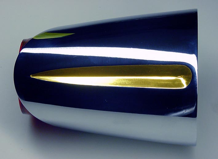
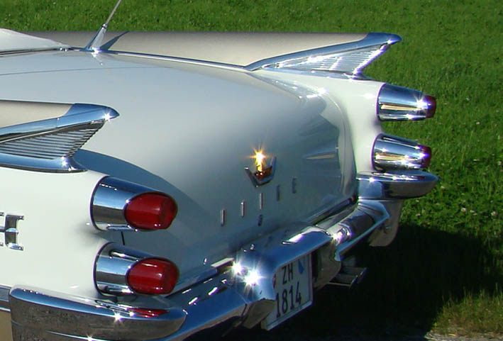
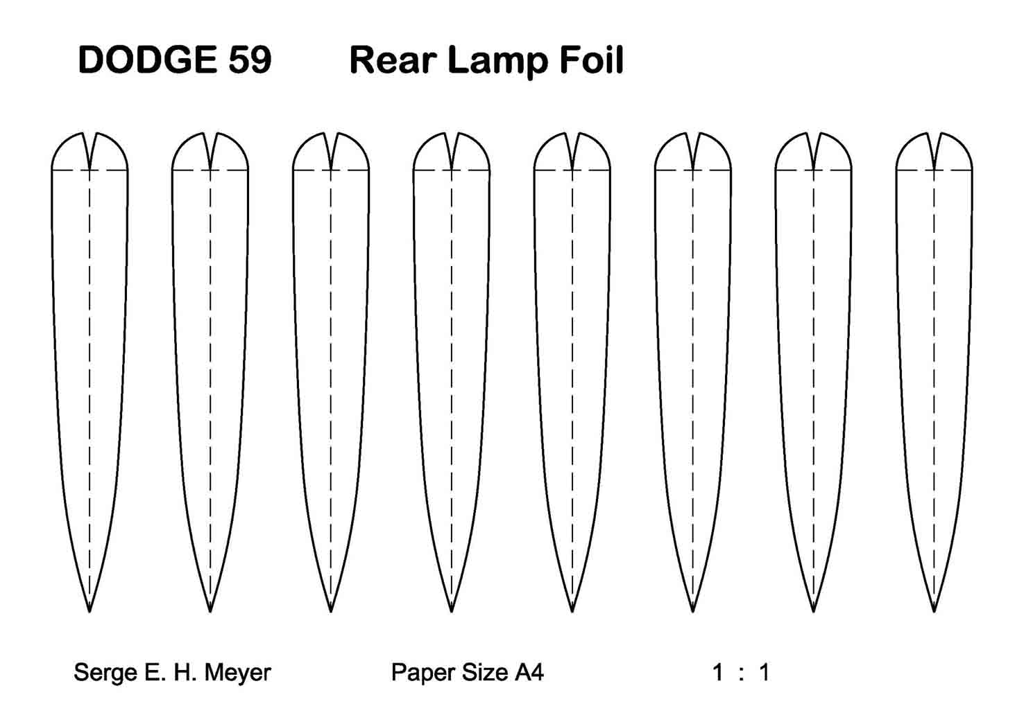
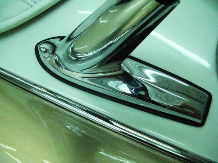
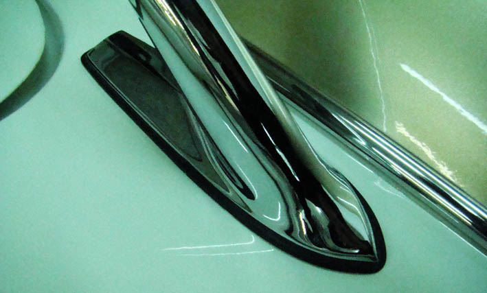
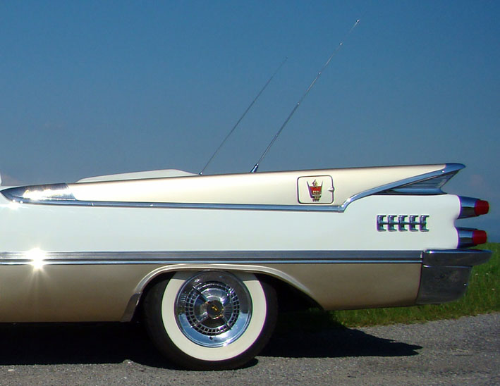
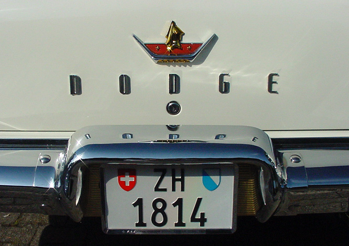
Location: SWITZERLAND | Rear Lamps: Theses Golden "Eye-Lines" have already attracted the attention of many people, using the same golden Foil as on the Door Handles. For a Dual Tone Car the corresponding Color would match even better - and it can be removed and redone instantly, without any chemical or disassembly. Print-out the PDF-File on A4 Sticking-Sheet (will be 1:1), then stick one sample on the Color Foil (color-Side) and cut-out around accordingly. Before applying fold the sample in the center for best positioning, remove the protecting layer, and at the end the sticked sample. Good News for Dodge 59 Owners?
(If your Foil is heat-resistent (Laser Printer!) you not need a Sticking-Sheet and can print directly on the protecting layer of the Foil Check first!)
Later on I will put another "Rear Lamps" talking on the Light.
Edited by sermey 2008-12-26 4:52 PM
 (DSC00035 DODGE59 Rear Lamp .jpg) (DSC00035 DODGE59 Rear Lamp .jpg)
 (DSC00200L Rear Lamps.jpg) (DSC00200L Rear Lamps.jpg)
 (Dodge59 Rear Lamp Foil copy.jpg) (Dodge59 Rear Lamp Foil copy.jpg)
Attachments
----------------
DSC00035 DODGE59 Rear Lamp .jpg (47KB - 871 downloads)
DSC00200L Rear Lamps.jpg (76KB - 886 downloads)
Dodge59 Rear Lamp Foil copy.jpg (82KB - 880 downloads)
Dodge59 Rear Lamp Foil.pdf (42KB - 876 downloads)
|
|
| |
|
Expert
Posts: 1215
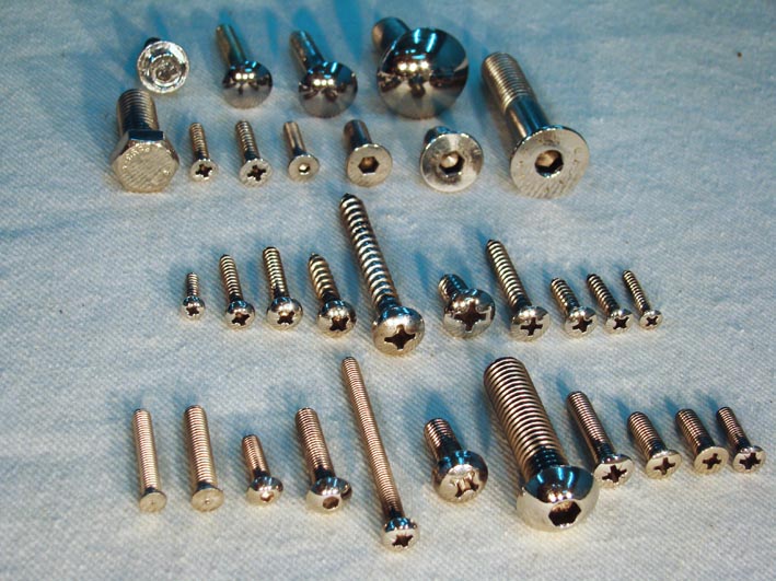
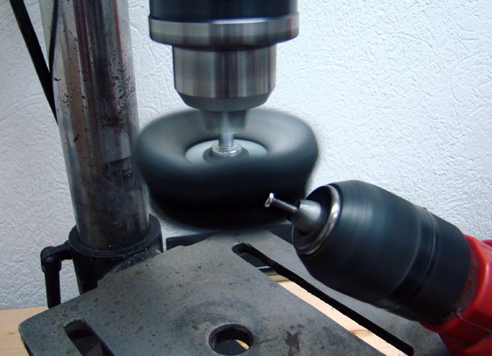
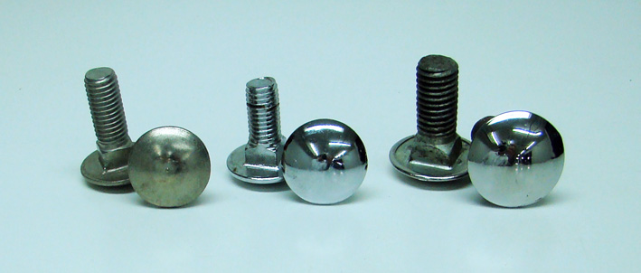
Location: SWITZERLAND | Screws 1: "No rusty Scews anymore!" I whished and decided to use only stainless (rustfree, 18/8) Screws where not excessive Stability is required. Most Platings (zinc, chrome, nickel, promat, etc.) on iron/steel Screws are not a Guarantee for no rust in a Temperature, Acid and all Weather exposed Ambient. The Rust is programmed as soon the Plating is damaged, what already may happen when you use them the first time. On a white painted Car as mine, any rusty Water will left visible Tracks. The stainless Screws are much more solid than standard Screws. They can be modified in Lenght and Head-Shape as you need or like it, and finally be polished, as shown when just having simple Tools disposable. Important for a nice rounded Result: the Screw and the Tool must turn in a high Speed and in 90deg Direction each to other.
The first Picture shows various Screws with polished Heads I used for my Car: Row3/5 Arm Rests, Row3/6 over the Head Lamps Dodge59, Row2/6 Door Latch. Mostly used on FWL-Cars Row 3/8-9 for Interior and Mirrors.
Edited by sermey 2008-12-27 3:26 PM
 (DSC02045 Screw Types.jpg) (DSC02045 Screw Types.jpg)
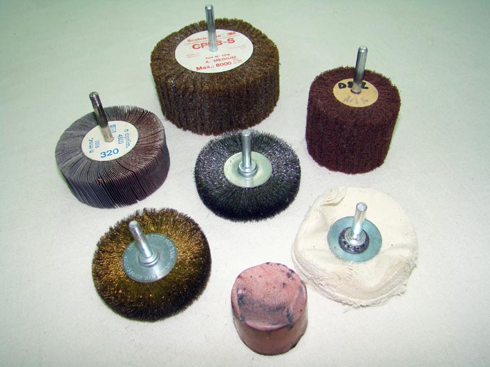 (DSC02054L Polishing Tools.jpg) (DSC02054L Polishing Tools.jpg)
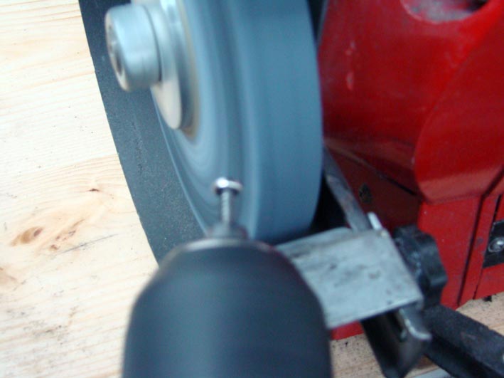 (DSC02060L Resizing Head.jpg) (DSC02060L Resizing Head.jpg)
 (DSC02057L Polishing Head.jpg) (DSC02057L Polishing Head.jpg)
Attachments
----------------
DSC02045 Screw Types.jpg (108KB - 895 downloads)
DSC02054L Polishing Tools.jpg (83KB - 839 downloads)
DSC02060L Resizing Head.jpg (53KB - 873 downloads)
DSC02057L Polishing Head.jpg (73KB - 824 downloads)
|
|
| |
|
Board Moderator & Exner Expert 10K+
Posts: 13062
Location: Southern Sweden - Sturkö island | I use the same method as Serge and I can confirm the good result obtained by using a drilling machine, mounting the object in the mandrel, running high speed in 90 degree angle agains the polish dish - stainless steel comes to mirror shine. |
|
| |
|
Expert
Posts: 1215
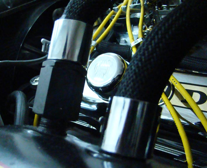
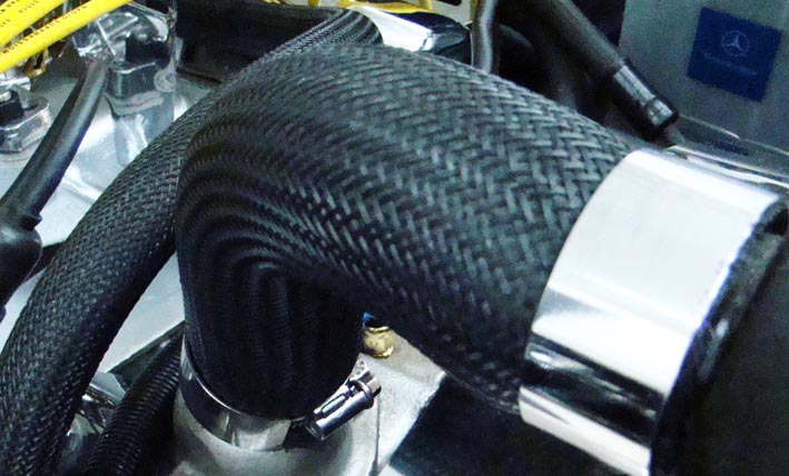
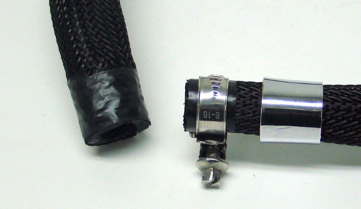
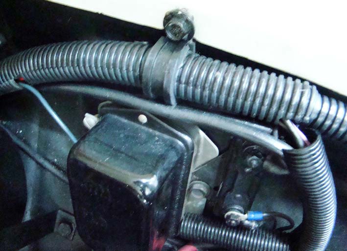
Location: SWITZERLAND | Hoses: There are many ways to get nice Hoses, using various Materials and Colors. The simplest is just to have stainless/rustfree Clamps and polish them as done with the Screws. See the difference standard - stainless. You can invest a fortune for the Hoses using sophisticated anodized Aluminium Ends and silver metallic Hose Coats, instead of black non-metal as I used. This black Coat keep its appearance, doesn't get mat or show any black oily Tracks. It is not expensive, easy to assemble and gives a discreet Look. There are different Sizes availabe as shown in the Picture. Only the Radiator End Covers I had to make with a Rest of the stainless Exhaust Tube, because not found (cut and polish!). After first mounting the hose and then the Coat, the black adhesive Tape around is for pre-fixing and avoiding possible damage by the Clamps. The Chrome Hose End Covers comes over the Clamp, leaving the Screw and End outside. The Clamp can be re-tighten at any time without removing any Part.
 (DSC02124L Vacuum Hose.jpg) (DSC02124L Vacuum Hose.jpg)
 (DSC02122L Radiator Hose.jpg) (DSC02122L Radiator Hose.jpg)
 (DSC02125L Heater-Fuel Hose.jpg) (DSC02125L Heater-Fuel Hose.jpg)
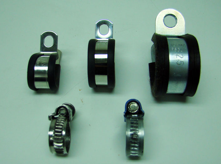 (DSC02130L Hose Clamps.jpg) (DSC02130L Hose Clamps.jpg)
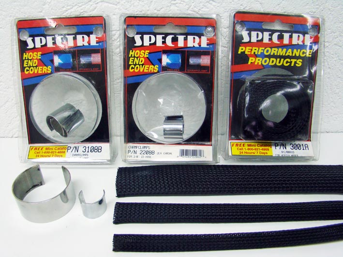 (DSC02128L Hoses Covers.jpg) (DSC02128L Hoses Covers.jpg)
 (DSC02134L Hose Assembling.jpg) (DSC02134L Hose Assembling.jpg)
Attachments
----------------
DSC02124L Vacuum Hose.jpg (87KB - 853 downloads)
DSC02122L Radiator Hose.jpg (85KB - 888 downloads)
DSC02125L Heater-Fuel Hose.jpg (116KB - 850 downloads)
DSC02130L Hose Clamps.jpg (63KB - 867 downloads)
DSC02128L Hoses Covers.jpg (108KB - 932 downloads)
DSC02134L Hose Assembling.jpg (57KB - 881 downloads)
|
|
| |
|
Expert
Posts: 1215
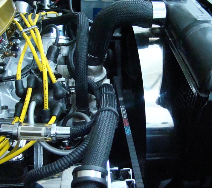
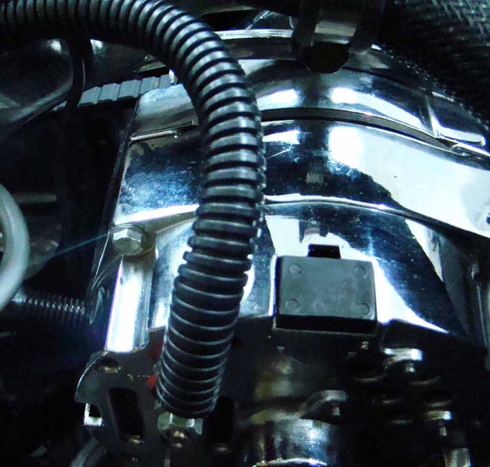
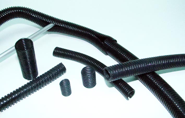
Location: SWITZERLAND | Wires: As for Hoses there are various Solutions to package and protect the wires. First I was suggested to use "self-merging" Tape. Then I listed up my demands for "tubing" the wires/cables on my Car: - Add and remove Wires at any time without "restarting" the job.
- Adapting the diameter when starting with one and ending with multiple Wires. - Possibility to Branch off a Cable at any position. - Flexible, compact and heat-resistant, in sufficient Lenght available.
The (split) Tubes I used are shown in different Sizes (the big Sizes are missing). They can lead from one Size to the next Size by overlapping. For "closed" Applications two Tubes are being twisted one into another. Easy replaceable to another Size when adding or removing Cables. To cut with a Knife. Applications to see also on earlier Pictures. I think these Tubes could also be used for Water and Fuel Hoses!?!
Edited by sermey 2008-12-30 10:40 AM
 (DSC02135L Alternator OneWire.jpg) (DSC02135L Alternator OneWire.jpg)
 (DSC02136L Crossover Sizes.jpg) (DSC02136L Crossover Sizes.jpg)
 (DSC02153L Wire Tubes.jpg) (DSC02153L Wire Tubes.jpg)
Attachments
----------------
DSC02135L Alternator OneWire.jpg (80KB - 867 downloads)
DSC02136L Crossover Sizes.jpg (74KB - 856 downloads)
DSC02153L Wire Tubes.jpg (65KB - 831 downloads)
|
|
| |
|
Expert
Posts: 1215
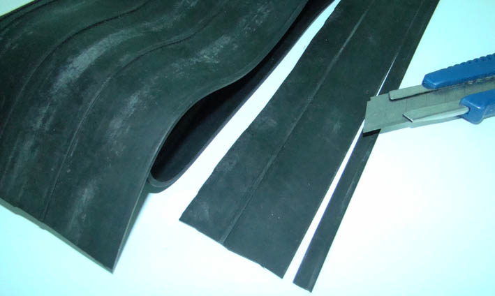
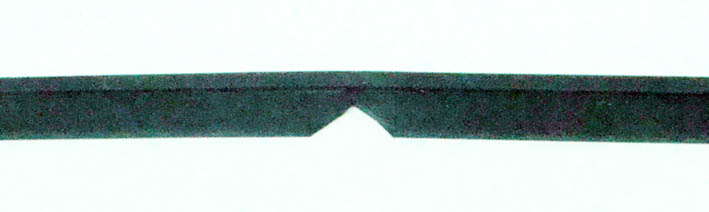
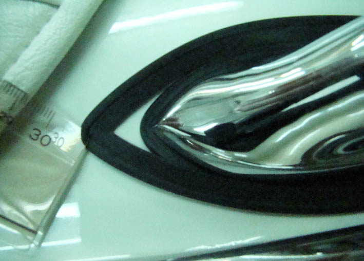
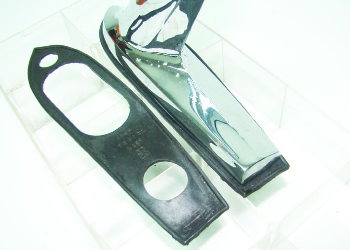
Location: SWITZERLAND | Dual Antenna Gaskets: With my Car I got a complete Set of Rubber Parts. Most of them I could not use, the Gaskets for the Dual Antennas being to big. I looked for a compatible Rubber Profile, best I could find was a wide sealing Strip (see Picture) with a useable Profile (Border Width 2.4mm, Border Height 2.25mm, Support Thickness 1.5mm). I cut this in the minimum Lenght of circumference (at Width 8mm). In the Middle of this Stripe I cutout a corner to match the front angle of the Antenna Socket. With the Antenna already mounted but not tightened, I pushed fully in the Rubber Profile around the socket. On the rear, two other 90deg angles had been cutout on the job, the Lenght adapted to meet in the Center of the rear Side. (N.B I left the mounted Gasket in Picture Start Mounting!)
Important: starting with the Front, the front scew underneath has to be tighten first for pre-fixing the Rubber. At this point the Rubber should be pulled on both sides along the Socket to find the correct 90deg angle position, before cutting out. Finally the second Screw of the Socket can be tighten, as the first too. The Gasket fits all around as illustrated.
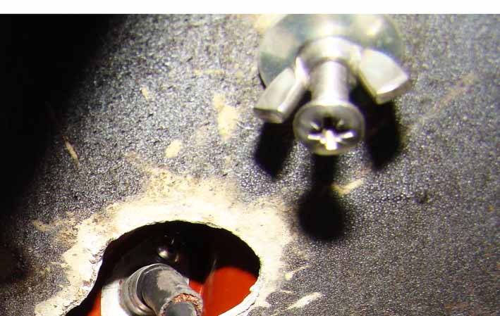
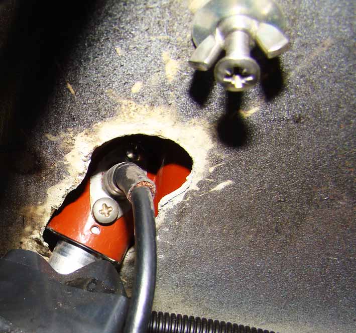
The Advantages of this Gasket: For replacing or changing, no Cables nor the Socket have to be removed. The Rubber is softer than the said Gasket and assures best Protection from entering Water in the Trunk. And last but not least, it looks professional.  I added the last Picture showing how to tighten the Socket, because hardly accessible (first fix a long screw, then manually tighten the wing nut, no tools!)
Edited by sermey 2008-12-30 5:39 PM
 (DSC02170L Left Side View.jpg) (DSC02170L Left Side View.jpg)
 (DSC02171L Right Side View.jpg) (DSC02171L Right Side View.jpg)
 (DSC02154L Preparing Profile.jpg) (DSC02154L Preparing Profile.jpg)
 (DSC02174L Cut Front Corner.jpg) (DSC02174L Cut Front Corner.jpg)
 (DSC02169L Start Mounting.jpg) (DSC02169L Start Mounting.jpg)
 (DSC02202L Manually Thighted Socket.jpg) (DSC02202L Manually Thighted Socket.jpg)
Attachments
----------------
DSC02170L Left Side View.jpg (92KB - 846 downloads)
DSC02171L Right Side View.jpg (66KB - 877 downloads)
DSC02154L Preparing Profile.jpg (50KB - 828 downloads)
DSC02174L Cut Front Corner.jpg (29KB - 840 downloads)
DSC02169L Start Mounting.jpg (69KB - 879 downloads)
DSC02202L Manually Thighted Socket.jpg (70KB - 887 downloads)
|
|
| |
|
Expert
Posts: 1215
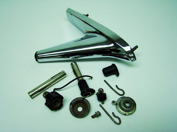
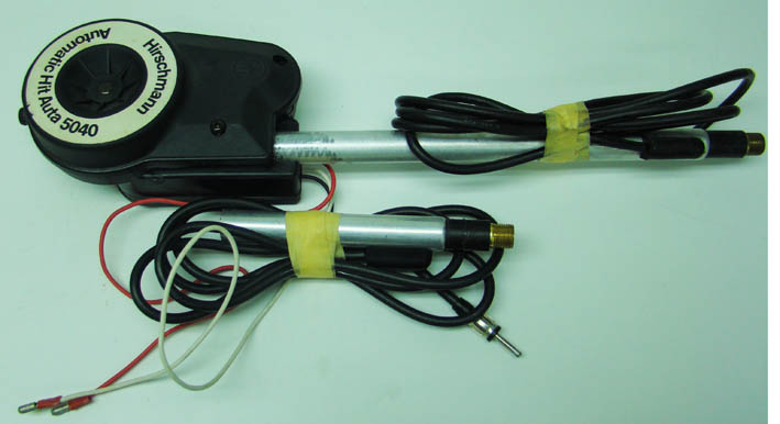
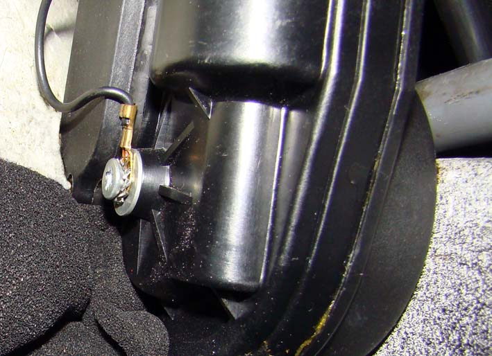
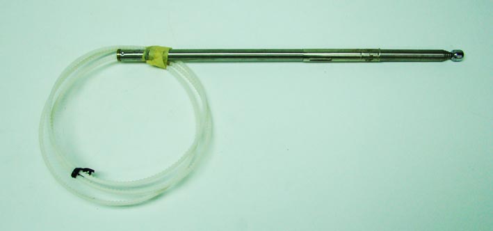
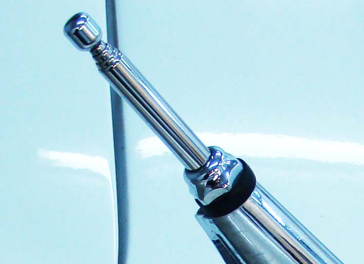
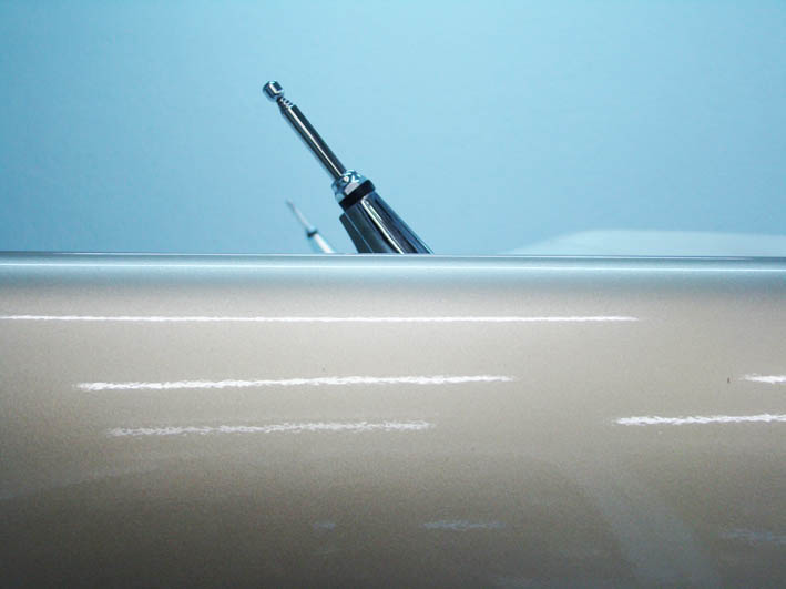
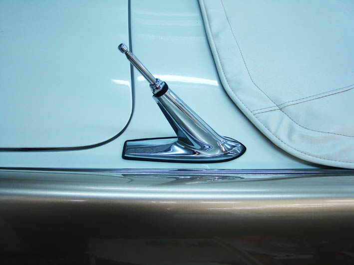
Location: SWITZERLAND | Rear Dual Power Antennas: Most Mopar-Owners wishes to have Rear Dual Antennas. Then, they would like to have them as Power Antennas. I must say: It is really an eye-catcher watching to these two Antennas when coming out together - each one want to be the first on Top! I felt a mess all this many parts, and thinking when must change the Antenna Bar (!), if ever a replacement is disposable. I found it easier to built-in a Power Module than to rebuild the Standard Antenna. I took two most used Power Antenna Units (new), shorted the Aluminium Tube according the Height of the Mopar Socket, drilled a bigger hole in the Mopar Antenna Socket - thats it! Mounting - easy! Hold the Power Unit in the Trunk down-up first without fixing it, insert from top the Mopar Antenna Socket and fixed it. Now the correct Position where the Antenna has to be mounted is given. It needs just one long single Screw that leads direct through the Center of the Power Unit to the Fold of the Wheelhouse in the Trunk (see Picture).The lateral adjustment to be vertical was done with washers as distance elements (right side fits exact without any additional positioner). The two Antennas have to be parallel, view from ANY Position.
Now: A broken bar can instantly be replaced. Simply remove the visible Bar Nut and pull the old Bar out. When inserted, the new Antenna Bar is automatically fed in. It is in stainless / rustfree Steel, polished will be shiny (as earlier mentioned the Screws and Hose Clamps). In OFF-Position the new Bar goes more inside than the Mopar Bar. I feel this even nicer - and a smaller risk that an unhappy Guy will brake them. The Bar is a little bit shorter than the original one, therefore has a better FM reception. Both Antenna Units are controlled in parallel by a separate Switch, mounted lefthand under the dashboard. Before the Mopar Antenna was laterally weak being fixed only on the Bodys Metal Sheet by the two Screws of the Mopar Socket. Now, the second Mount by the Power Unit assures a stiff Stability all around.
To know: The Dual Antennas are originally RF-connected in parallel (Y). This worked well at the time with AM. With an FM-Radio Interference could occur. I connected the left Antenna to the Original AM Radio (Center Loudspeaker). The right Antenna goes to the FM Radio in the Glove Compartment (Surround STEREO Loudspeaker).
Edited by sermey 2008-12-31 5:26 AM
 (DSC02178L Antenna Parts.jpg) (DSC02178L Antenna Parts.jpg)
 (DSC02179L Power Unit.jpg) (DSC02179L Power Unit.jpg)
 (DSC02198L Antenna Mounts.jpg) (DSC02198L Antenna Mounts.jpg)
 (DSC02202L Antenna Connection.jpg) (DSC02202L Antenna Connection.jpg)
 (DSC02181L Bar Replacement.jpg) (DSC02181L Bar Replacement.jpg)
 (DSC02208L Bar Nut.jpg) (DSC02208L Bar Nut.jpg)
 (DSC02204L Antenna Height.jpg) (DSC02204L Antenna Height.jpg)
 (DSC02208L Antenna Full View.jpg) (DSC02208L Antenna Full View.jpg)
 (DSC00195L Dual Power Antennas.jpg) (DSC00195L Dual Power Antennas.jpg)
Attachments
----------------
DSC02178L Antenna Parts.jpg (56KB - 874 downloads)
DSC02179L Power Unit.jpg (53KB - 871 downloads)
DSC02198L Antenna Mounts.jpg (90KB - 848 downloads)
DSC02202L Antenna Connection.jpg (97KB - 866 downloads)
DSC02181L Bar Replacement.jpg (26KB - 936 downloads)
DSC02208L Bar Nut.jpg (45KB - 843 downloads)
DSC02204L Antenna Height.jpg (44KB - 910 downloads)
DSC02208L Antenna Full View.jpg (55KB - 861 downloads)
DSC00195L Dual Power Antennas.jpg (75KB - 812 downloads)
|
|
| |
|
Expert
Posts: 1215
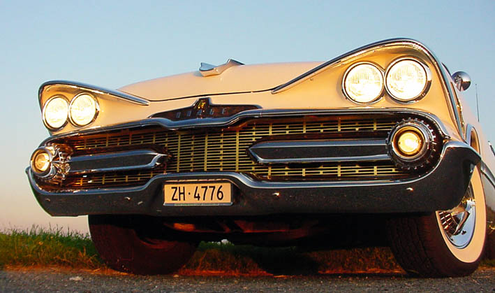
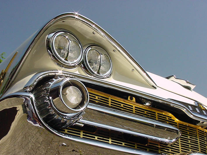
Location: SWITZERLAND | Front Grill: Another "Make-Up" the golden anodized Front Grill. If like or not, just must see! I found otherwise too much silver. Pictures taken at US-Car Meeting when won "Best of Show": Me and my 1959 Dodge Custom Royal Lancer Convertible.
Edited by sermey 2008-12-31 5:15 AM
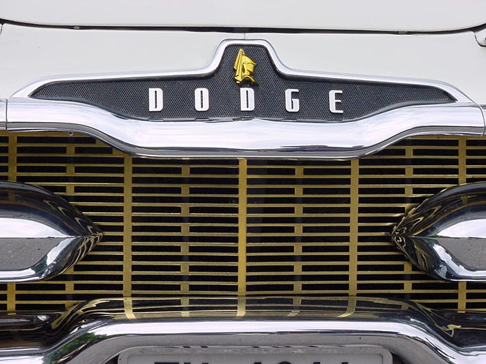 (DSC00022L Golden Grill.jpg) (DSC00022L Golden Grill.jpg)
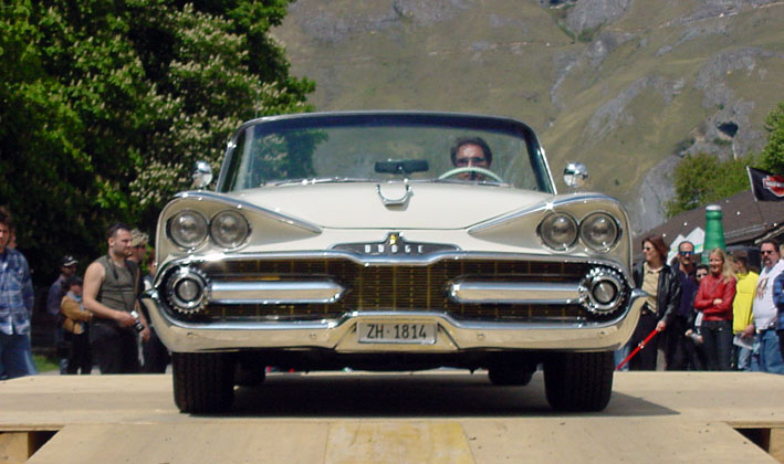 (DSC00037L Front.jpg) (DSC00037L Front.jpg)
Attachments
----------------
DSC00022L Golden Grill.jpg (109KB - 836 downloads)
DSC00037L Front.jpg (99KB - 837 downloads)
|
|
| |
|
Expert
Posts: 1215
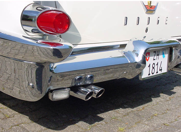
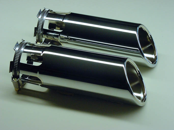
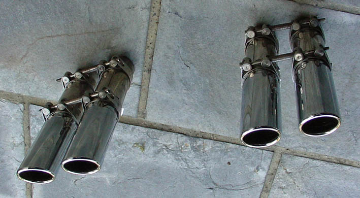
Location: SWITZERLAND | Exhaust Outlets: Another tricky "Make-Up" or say Show-Element are the Quad Exhaust Outlets. It remember at nice, long Blond-Hair Ladies, the Hairs being "Dummies", but we still like and look at them. I found the Dual Exhaust Outlets too much in the Center. Adding two additional virtual Outlets moves them optically to the right Direction outside. Among various available items I selected these stainless Outlets because they matched best to the rear Side-Profile of the 1959 Dodge. The mounting items, as illustrated, are also in stainless / rustfree Steel. This Mount System allows to adjust individually the Distance between the twin Outlets. Here again: this can be restored at any time to its original state!
Edited by sermey 2008-12-31 6:24 AM
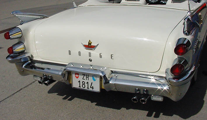 (DSC00043L Quad Exhaust Outlets.jpg) (DSC00043L Quad Exhaust Outlets.jpg)
 (DSC00019L Dual Exhaust Outlet.jpg) (DSC00019L Dual Exhaust Outlet.jpg)
 (DSC00069L Exhaust Outlets.jpg) (DSC00069L Exhaust Outlets.jpg)
 (DSC00013L Quad Outlet Mounts.jpg) (DSC00013L Quad Outlet Mounts.jpg)
Attachments
----------------
DSC00043L Quad Exhaust Outlets.jpg (66KB - 849 downloads)
DSC00019L Dual Exhaust Outlet.jpg (97KB - 853 downloads)
DSC00069L Exhaust Outlets.jpg (64KB - 829 downloads)
DSC00013L Quad Outlet Mounts.jpg (74KB - 811 downloads)
|
|
| |
|
Expert
Posts: 3575
Location: Netherlands | To me, that convolute tubing screams late 70s enginebay to me and I've hated it ever since I first saw it. Definitly not a "Make-UP" in my eyes 
Pretty much same goes for the cheap Spectre hose-wrap. Yuk!
On a driver, one way to get caught with fuel-spills in de engine-bay is to put that braided stuff in there so you'll never see the condition of the fuelline underneath. The rubber usually dries up and the hoses start to develop cracks and tears and can start leaking at/on/during the most inconvenient locations.
Other than that, nice info and some good tips there.
Thanks for sharing! |
|
| |
|
Expert
Posts: 1215
Location: SWITZERLAND | BigBlockMopar - 2008-12-31 5:56 PM To me, that convolute tubing screams late 70s enginebay to me and I've hated it ever since I first saw it. Definitly not a "Make-UP" in my eyes Pretty much same goes for the cheap Spectre hose-wrap. Yuk! On a driver, one way to get caught with fuel-spills in de engine-bay is to put that braided stuff in there so you'll never see the condition of the fuelline underneath. The rubber usually dries up and the hoses start to develop cracks and tears and can start leaking at/on/during the most inconvenient locations. Other than that, nice info and some good tips there. Thanks for sharing! Nice open minded comment, Herman. You are right, many "Make-Ups" of today are crazy - not only on Cars. Some like it, other don't. My aim with this tread is to motivate many Car owners to "upgrade" their cars with moderate effort, but visible effect. Here I just present what I did on my car now 10 Years ago, and I am happy when people look at, may find something useful and / or just state comments as you. Thank you.
Now to the Hoses: Yes, cannot see the condition of this hoses - nor of my veins! Today hoses are not just Rubber as 50 Years ago. These old ones cracks and tears as you correctly alerted. The Material Technology has experienced extreme Developments in the last years. According the application there are Hoses in any other Material than Rubber (PVC, Polyurethan, Silicon, Elastomer, Nitril) for Longlife use. The fuelline hose I use is especially designed for this, it has already a stuff around, wraped again for uniformity reasons. Bought recently again for my new Dual Quad Project I will report here soon. To the Spectre Hose Wrap: I liked this Design and have given my Argumets for. It was not a question of costs. Cheap doesn't mean bad. My Golden Coating on the Knights costs nothing, but is even more shiny than pure Gold.
|
|
| |
|
Expert
Posts: 1215
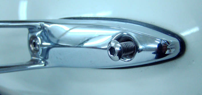
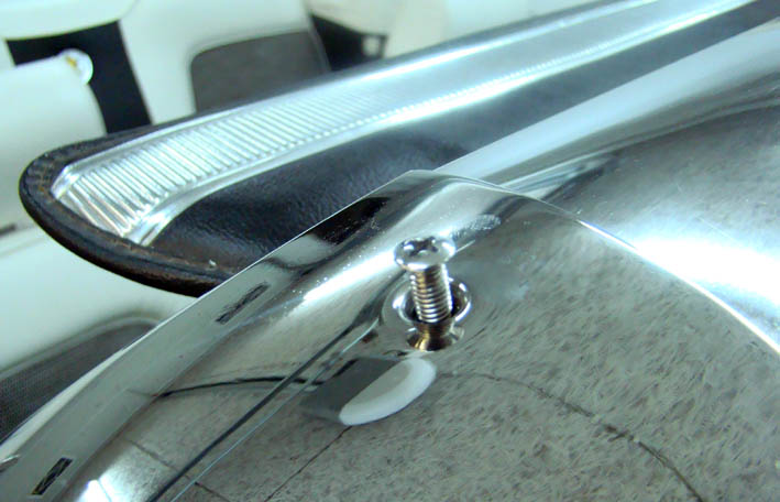
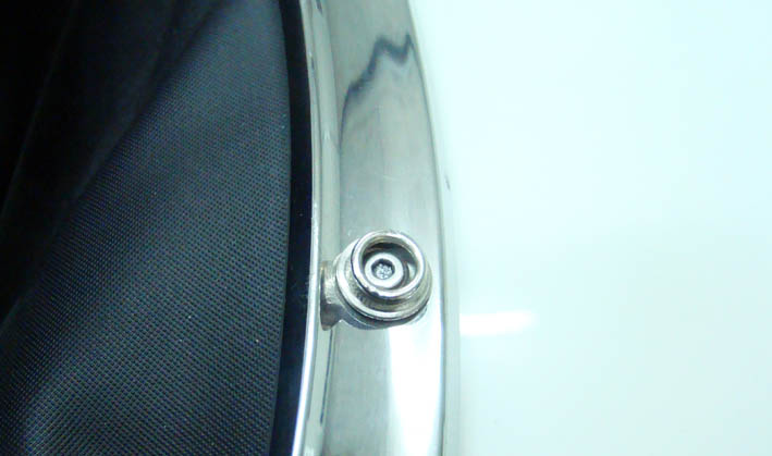
Location: SWITZERLAND | Screws 2: Self-tapping Screws are most efficient in the manufacturing process. They are self-centering in direction and angle, in opposite to Thead-Screws. Nevertheless I have substituted most self-tapping Screws by stainless / rustfree Thread-Screws.
- no damage of newly painted body (rust)
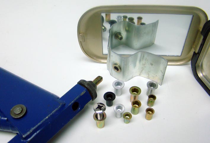
- some holes got too big - option for other heads - higher precision For this I had to insert the nuts (on body before painting) using a Hand-Tool. The mirrored item is the unvisible clip used in Pic2. Some outside accessible Screws I replaced with Intra Hexagon Head Screws (?) for they cannot be removed with any pointy knife, as possible with Standard Cross Head Screws (see Rear View Mirror).
Edited by sermey 2009-01-01 1:55 AM
 (DSC02232L Mirror Mount.jpg) (DSC02232L Mirror Mount.jpg)
 (DSC02231L Convertible Mold Mount.jpg) (DSC02231L Convertible Mold Mount.jpg)
 (DSC02233L Convertible Rear Top Mount.jpg) (DSC02233L Convertible Rear Top Mount.jpg)
 (DSC02230L Nut Press Tool .jpg) (DSC02230L Nut Press Tool .jpg)
Attachments
----------------
DSC02232L Mirror Mount.jpg (41KB - 839 downloads)
DSC02231L Convertible Mold Mount.jpg (70KB - 855 downloads)
DSC02233L Convertible Rear Top Mount.jpg (48KB - 833 downloads)
DSC02230L Nut Press Tool .jpg (54KB - 826 downloads)
|
|
| |
|
Expert
Posts: 1215
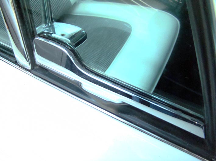
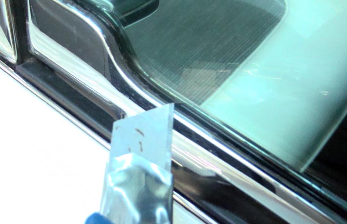
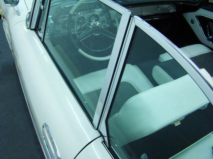
Location: SWITZERLAND | Window Rubber: Restoring another US-Car years ago I used successfully the same method to replace the damaged and missing Window Rubber. The lower Door Windows Channel was totally rusted. On my DODGE, the Rubber of the Pivot Windows was broken, any attempt with a cutted Rubber Stripe failed, the Windows didn't hold enough, at the curves the Rubber was shrinked and looked very bad. Thus I used again my old method: I put black Liquid Silicon Gasket in the chrome channels. Then I centered the Windows inserting small wood positioners inside, on the left and right side, and re-filled the gaps around with Liquid Silicon Gasket. After minimum one week or even longer the Silicon should be hardened trough, remaining softish, ready to cut out precisely the overflowed Silicon with a Knife (not cut towards the window!) . Now, the Window is fixed all around, absolute water-proof and exact flush with the Chrome Channel, even more accurate than using the original rubber because custom-sailored. I suggest this also for Door Windows when the Rubber Profiles are not available, or for repair leaky Windshields, Remermber: Silicon Products cannot be painted!
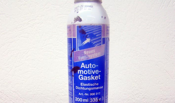
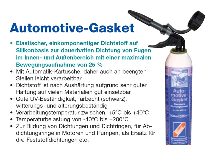
Any black Silicon Sealer can be used, should be heat resistant within -40 to +180deg, UV and all-wheather resistant (look at the Specs). Now I just found them ffrom the Producers of "Automotive Gasket" in the Internet and post it (sorry only in German). Same or similar surely available in US.
Edited by sermey 2009-01-01 2:12 AM
 (DSC02241L Window Rubber.jpg) (DSC02241L Window Rubber.jpg)
 (DSC02242L Cutting Out.jpg) (DSC02242L Cutting Out.jpg)
 (DSC02243L Silicon Gasket.jpg) (DSC02243L Silicon Gasket.jpg)
 (Automotive Gasket.jpg) (Automotive Gasket.jpg)
Attachments
----------------
DSC02241L Window Rubber.jpg (68KB - 873 downloads)
DSC02242L Cutting Out.jpg (63KB - 884 downloads)
DSC02243L Silicon Gasket.jpg (54KB - 853 downloads)
Automotive Gasket.jpg (109KB - 817 downloads)
|
|
| |
|
Expert
Posts: 1215
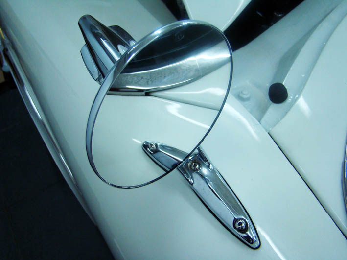
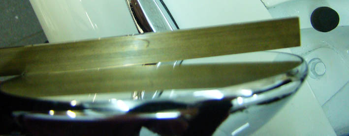
Location: SWITZERLAND | Rear View Mirror Glass: Restoring my Car I had to rechrome the Rear View Mirrors too and had for this to brake out the Glasses. I bought two bigger replacement Glasses as used for Trucks and let them cut excatly fitting in the now rechromed housing. To fix them I used again the before presented black Silicon - bonded and sealed in one! (on the Picture you can as well see in black the left and right Hood Positioners)
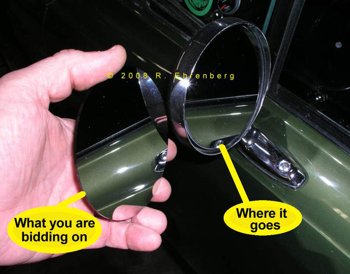
To add: I purchased two different Glasses, the one flat for the left side as used in all Mopar Mirrors, the other curved for the right side in order to get a wider viewing Angle (see Picture), as used in all todays cars. Last Month I saw such a flat Mirror Replacement for Mopars in eBay, I post the Picture.
Edited by sermey 2009-01-01 3:18 AM
 (DSC02246L New Mirror Glass.jpg) (DSC02246L New Mirror Glass.jpg)
 (DSC02244L Curved Mirror Glass.jpg) (DSC02244L Curved Mirror Glass.jpg)
 (2008 eBay Mirror Glass.jpg) (2008 eBay Mirror Glass.jpg)
Attachments
----------------
DSC02246L New Mirror Glass.jpg (63KB - 845 downloads)
DSC02244L Curved Mirror Glass.jpg (40KB - 871 downloads)
2008 eBay Mirror Glass.jpg (79KB - 852 downloads)
|
|
| |
|
Expert
Posts: 1215
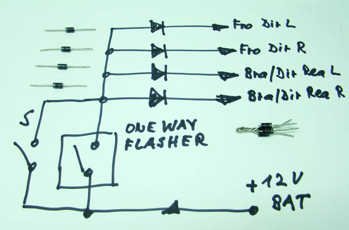
Location: SWITZERLAND | Four-Way Warning Flasher: Most FWL-Cars doesn't have the Option of a Warning Flasher, none my Car when I got it. For personal and emergency reasons this was a must and added this Feature. Four-Way means that the Flashing Signal goes in four Directions (please correct me if not): 1. to the Front Left Directional Light, 2. To the Front Right Directional Light, 3. To the Rear Left Directional (*and / or Brake) Light, 4. To the Rear Right Directional ("and / or Brake) Light. Thus, the Flasher has to provide four separate Current Lines. There will be one Input and four Outputs Connections. (* this depends if Brake Bulb is combined with Directional Signal)
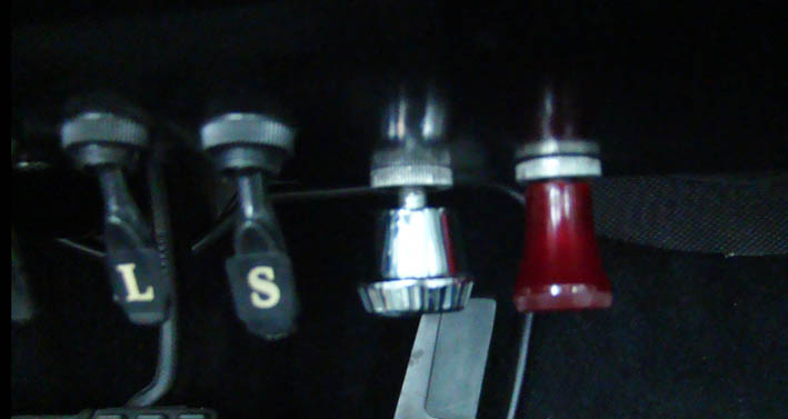
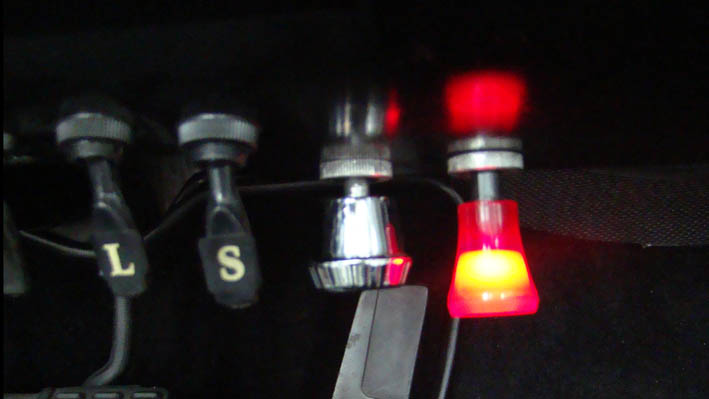
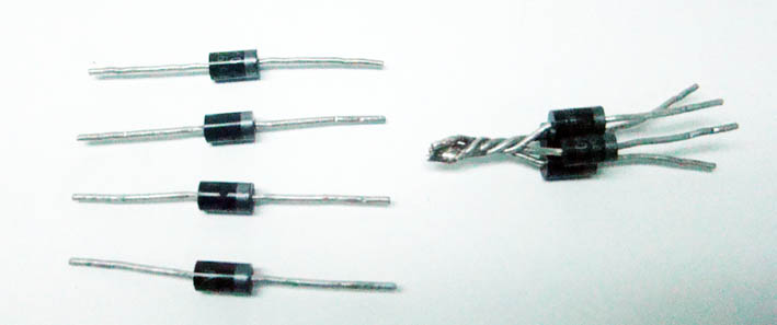
The same Function I realized it simpler by using a One-Way Flasher Unit and four Diodes, as connected according the hand-drafted Diagram. The Input has to come directly from the Battery +12V to assure an operation in any circumstances. The Single (switched) Output of the Unit goes to the four (twisted) Diodes. The Outputs of the Diodes are then wired to the four Directions, as described. All these 5 needed Wires are easy to found under the Dashboard - no extra long wires required! Check with an Instrument by Switching on and off the Functions (Brakes, Directional Light) and be sure you take the wires leading directly to the corresponding Bulb. The Flasher Unit should have a good visible Control-Lamp. Best I found was a Unit, mounted under the Dashboard, needind a single Hole 1/2" for mount, and pull-out for ON. The used Diodes 1N5401 (100V/3A or higher Values), Standard Types available in any (?) electronic Shop (about USD1.00). To the "Make-Up" or better to the Show-Effect: The Red Knob is the Flasher, the Silver Knob left-hand the Clock-Adjustment, and next you see the Switch S. This Swicht by-passes the Flashing (not the Diodes!!!), all Lamps around are continuous ON for "Show-Time" at evening, at Night or for Night-Pictures -Happy flashing with the Camera. (The Headlamps have to be swichted ON separately, the last Switch L add the two other Headlamps).
Edited by sermey 2009-01-01 2:55 PM
 (DSC02279L Flasher Switch OFF.jpg) (DSC02279L Flasher Switch OFF.jpg)
 (DSC02284L Flasher Switch ON.jpg) (DSC02284L Flasher Switch ON.jpg)
 (DSC02285L Diagram.jpg) (DSC02285L Diagram.jpg)
 (DSC02288L Diodes 1N5401.jpg) (DSC02288L Diodes 1N5401.jpg)
Attachments
----------------
DSC02279L Flasher Switch OFF.jpg (41KB - 834 downloads)
DSC02284L Flasher Switch ON.jpg (42KB - 882 downloads)
DSC02285L Diagram.jpg (60KB - 851 downloads)
DSC02288L Diodes 1N5401.jpg (32KB - 859 downloads)
|
|
| |
|
Expert
Posts: 1215
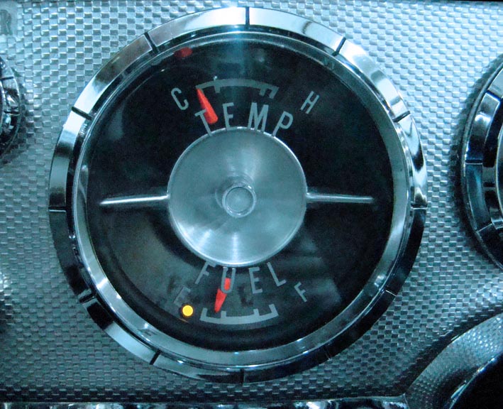
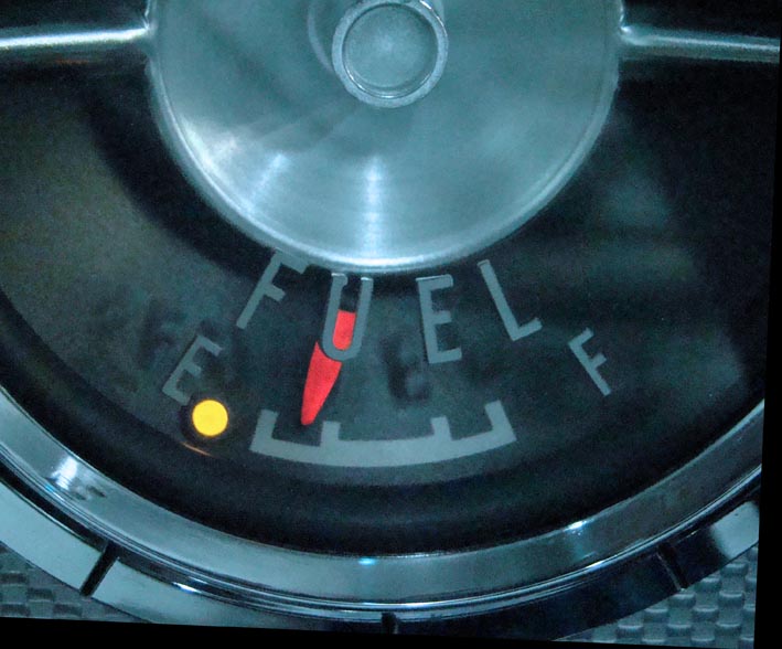
Location: SWITZERLAND | Fuel Temp Gauge: I was always used to know how many km the car will run when the Empty Fuel Alert Light went on. This I missed on my Dodge. When restoring the Instruments I added a bright Yellow LED. In the Fuel Tank I had to add an adjustable Switch and a separate wire leading to this LED. In the restoring Process this was not a big work. First I wanted design a Trigger-Circuit (2 - 3 Transistors) switching on the LED at an calibrated Resistor / Voltage Value on the existing line to the Fuel Instrument. Thinking this value could vary due to instable Main-Voltage (the internal regulator works imprecisely) I decided to go the "traditional" way. When OFF the LED is not visible.
Now, the LED goes on always exactly at the same Fuel Level - in this regard happy driving and no Stress anymore!
Edited by sermey 2009-01-01 5:00 PM
 (DSC02305L Fuel Temp Gauge.jpg) (DSC02305L Fuel Temp Gauge.jpg)
 (DSC02306L Empty LED ON.jpg) (DSC02306L Empty LED ON.jpg)
Attachments
----------------
DSC02305L Fuel Temp Gauge.jpg (126KB - 876 downloads)
DSC02306L Empty LED ON.jpg (83KB - 890 downloads)
|
|
| |
|
Board Moderator & Exner Expert 10K+
Posts: 13062
Location: Southern Sweden - Sturkö island | Thank you very much for your information about the 4-way flasher Serge! I have been looking after an old system for to add on my car, but with your diagram and notes it will be easy to build one. |
|
| |
|
Expert
Posts: 1215
Location: SWITZERLAND | wizard - 2009-01-01 11:33 PM Thank you very much for your information about the 4-way flasher Serge! I have been looking after an old system for to add on my car, but with your diagram and notes it will be easy to build one. I am glad that you Swen, as one of the many highly experienced FW Lookers on this site found something useful, as I wished for all old US-Car Owners. I know, not anythig in this Thread fits the taste of the Readers, but "There's no accounting for Taste". Many issues have already been discussed somewhere, I cannot know, others are still open. Thus, go on (and all other Car-Friends) keeping inspired by reading these and next next issues to come. - SERGE -
|
|
| |
|
Expert
Posts: 1215
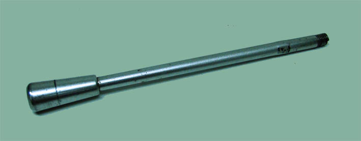
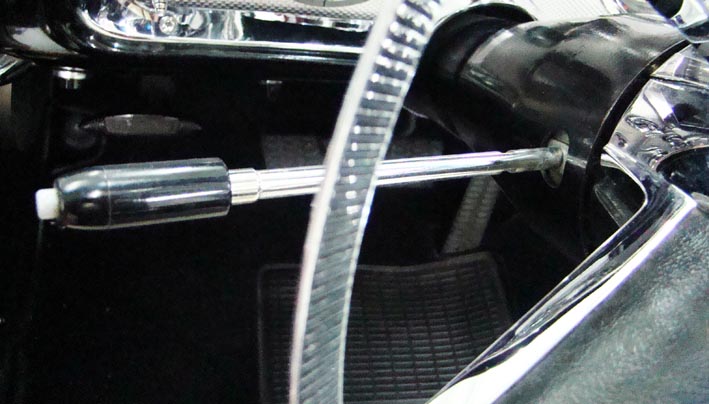
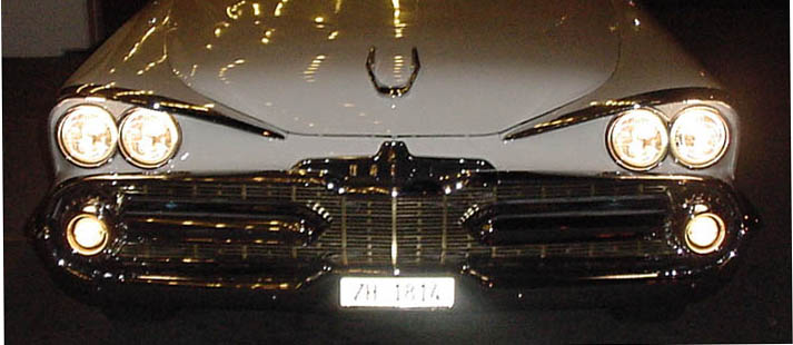
Location: SWITZERLAND | Head Lamp Flash: I also was used to have the Head Lamp Flash Feature, especially as alert to others in critical situations, mostly on the Highwayss. Fortunately I had already a Micro-Switch Unit I purchased "with great foresight" in double many Years ago for another US-Car. It needs one additional wire leading through the Steering Wheel Unit to a separate mounted Relais. As the Four-Way Warning Flasher this Option works at any time, by-passing all the Head Lamp Circuits. At ON all four Head Lamps (both Bulb Wires!) work together to get the maximum bright Alert Light. It is not recommended to let them ON for longer time, the bulbs may got hot and damaged. Sometimes on the way just say "Hello" and flash the Head Lamps.
 (DSC02307L Original Directional Lever.jpg) (DSC02307L Original Directional Lever.jpg)
 (DSC02310L Switch Unit Headlamp Flash.jpg) (DSC02310L Switch Unit Headlamp Flash.jpg)
 (DSC00010L Head Lamp Flash ON.jpg) (DSC00010L Head Lamp Flash ON.jpg)
 (DSC00038L Head Lamp Flash ON.jpg) (DSC00038L Head Lamp Flash ON.jpg)
Attachments
----------------
DSC02307L Original Directional Lever.jpg (26KB - 893 downloads)
DSC02310L Switch Unit Headlamp Flash.jpg (71KB - 840 downloads)
DSC00010L Head Lamp Flash ON.jpg (58KB - 858 downloads)
DSC00038L Head Lamp Flash ON.jpg (82KB - 885 downloads)
|
|
| |
|
Expert
Posts: 1215
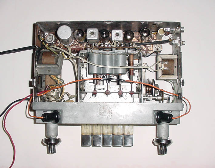
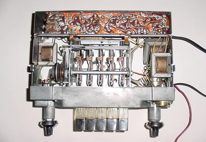
Location: SWITZERLAND | Radio: To repair a Radio is not easy when you are not familiar with nor have equipped for. Fortunately I have some Tools. What you can do: clean the Contacts and the Potentiometer using a Contact-Spray. I have soldered a shielded Cable with Cinch Connector between the Max and the Ground ot the Volume Control, in Serie with a Resistor of 100k. This is an AUX-Input (also Output without 100k) for external Audio-Devices. Can use an (portable) FM-Radio and connect it there. However the Sound Quality will not be much better due to the poor Output-Stage of the Radio.
The Loudspeaker was replaced by a better Quality one. The mounts fits but a corner of the Magnet must be removed or will touch the Dashboard. As printable PDF-File post-attached the Technical Instructions with Schematic Diagramm: MOPAR Radio 856/857, 6 Pages in 3 Steps (cannot Download 500kB).
Edited by sermey 2009-01-03 5:24 AM
 (DSC00051 MOPAR Radio.jpg) (DSC00051 MOPAR Radio.jpg)
 (DSC00123L Radio Top View.jpg) (DSC00123L Radio Top View.jpg)
 (DSC00122L Radio Bottom View.jpg) (DSC00122L Radio Bottom View.jpg)
 (1959 MOPAR Radio 856-857.jpg) (1959 MOPAR Radio 856-857.jpg)
Attachments
----------------
DSC00051 MOPAR Radio.jpg (82KB - 918 downloads)
DSC00123L Radio Top View.jpg (93KB - 862 downloads)
DSC00122L Radio Bottom View.jpg (99KB - 854 downloads)
1959 MOPAR Radio 856-857.jpg (142KB - 984 downloads)
1959 MOPAR Radio 856-857 1-2.pdf (175KB - 1073 downloads)
1959 MOPAR Radio 856-857 3-4.pdf (186KB - 963 downloads)
1959 MOPAR Radio 856-857 5-6.pdf (153KB - 920 downloads)
|
|
| |
|
Expert
Posts: 1215
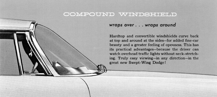
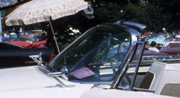
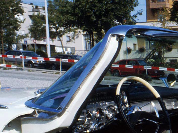
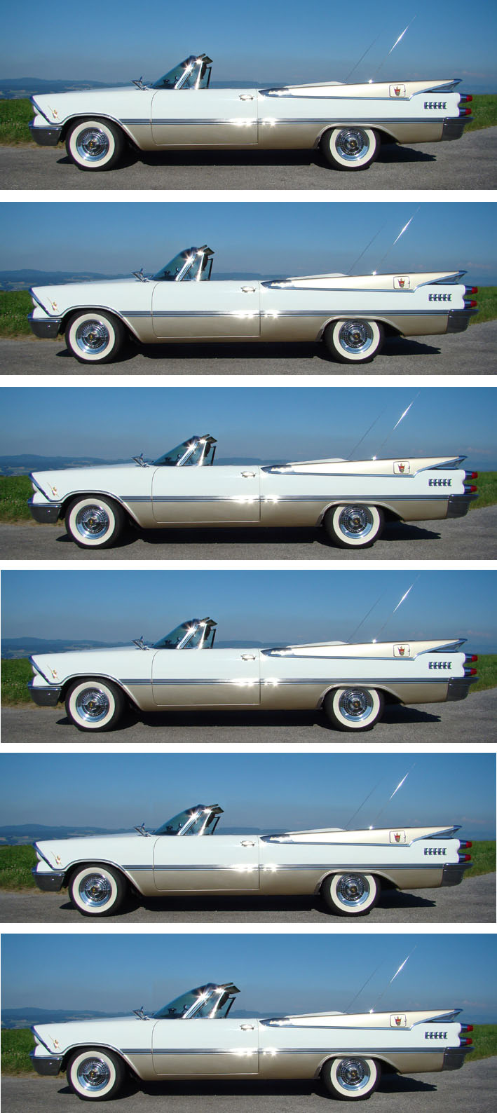
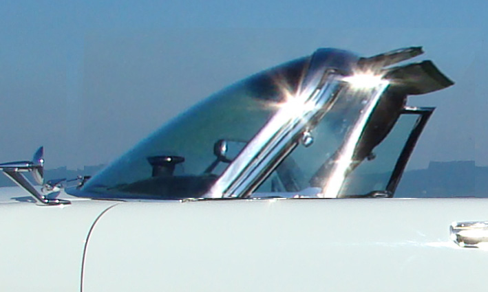
Location: SWITZERLAND | Curved Windshield: I was already asked if I have a Curved Windshield. Yes, I had it, but mat as sandblasted. I coudn't find anywhere a Curved one and had to take what was available. Finally I learned to like the new straight Windshield beeng more slanted. In a certain angle from side view you even can't see if it is curved or not. In my Fantasy I have modified my Windshield to various Stretched Curved Models - the last Version 7 (Double Stretched) I feel exciting! Looking at, then back to the Original, the actual one seems to be very "old-fashioned". Just to remember: it's an Oldtimer!
In the Collection I left the entire Car Size to get an integrate Impression.
1. My Car today, 2. Original Curved, 3. Stretched, 4. Streched Curved, 5. More Stretched, 6. More Stretched Curved, 7. Double Stretched Curved (and additional Zoomed).
Edited by sermey 2009-01-03 2:44 AM
 (Ross Roy-Curved Windshield.jpg) (Ross Roy-Curved Windshield.jpg)
 (Original Curved Windshield 1.jpg) (Original Curved Windshield 1.jpg)
 (Original Curved Windshield 2.jpg) (Original Curved Windshield 2.jpg)
 (Various Stretched Windshields.jpg) (Various Stretched Windshields.jpg)
 (Double Stretched Windshield Zoomed.jpg) (Double Stretched Windshield Zoomed.jpg)
Attachments
----------------
Ross Roy-Curved Windshield.jpg (70KB - 848 downloads)
Original Curved Windshield 1.jpg (58KB - 899 downloads)
Original Curved Windshield 2.jpg (99KB - 862 downloads)
Various Stretched Windshields.jpg (190KB - 879 downloads)
Double Stretched Windshield Zoomed.jpg (79KB - 965 downloads)
|
|
| |
|
Expert
Posts: 1215
Location: SWITZERLAND | Seat Ash Tray: As already apllied on the Door Handles and the Rear Lamps, the Golden Sticker on the Seat Ash Tray has its own optical Effect - a (Custom) Royal feeling for Smokers sitting behind. An Interior matched Color would be nice too.
Edited by sermey 2009-01-03 8:12 AM
 (DSC00010L Seat Ash Tray.jpg) (DSC00010L Seat Ash Tray.jpg)
Attachments
----------------
DSC00010L Seat Ash Tray.jpg (75KB - 891 downloads)
|
|
| |
|
Expert
Posts: 1215
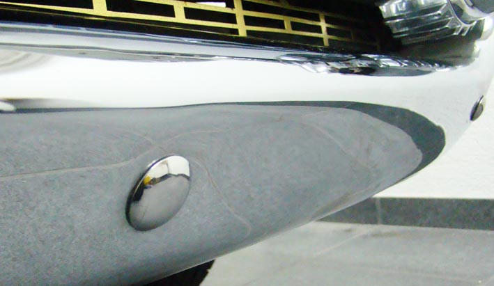
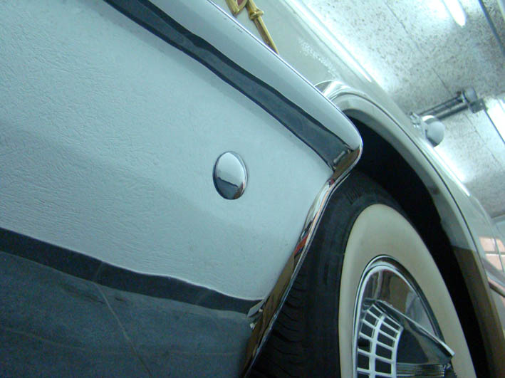
Location: SWITZERLAND | Bumper Bolts: Shiny polished Bumper Bolts underlines a nice restoration. In the Sun or at Spotlight they may shine as small Brillants around the car. Some are less visible, other more. There are different Types, the mostly used hardened Steel with a stainless Cover, then the rechromed and the all stainless / rustfree ones to be handeled and polished as the other Screws. For the main Front and Rear Bumpers I used the "covered" ones, on the sides and up-side the smaller rechromed ones I had already. Do not tighten to hard as I did: somewhere the Chrome of the Bumper started to brake around the Head, the Support-Arm being not exactly parallel with the Bumper. Should put a Nylon Washer for compensation. I like the last picture and post it at higher Quality.
Edited by sermey 2009-01-03 9:10 AM
 (DSC02324L Bumper Bolts.jpg) (DSC02324L Bumper Bolts.jpg)
 (DSC02321L Front Bumper Bolts.jpg) (DSC02321L Front Bumper Bolts.jpg)
 (DSC02323.L Side Bumper Bolt.jpg) (DSC02323.L Side Bumper Bolt.jpg)
 (DSC00006L Rear Bumper Support.jpg) (DSC00006L Rear Bumper Support.jpg)
Attachments
----------------
DSC02324L Bumper Bolts.jpg (71KB - 891 downloads)
DSC02321L Front Bumper Bolts.jpg (56KB - 896 downloads)
DSC02323.L Side Bumper Bolt.jpg (74KB - 891 downloads)
DSC00006L Rear Bumper Support.jpg (140KB - 893 downloads)
|
|
| |
|
Expert
Posts: 1215
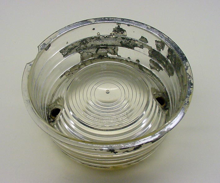
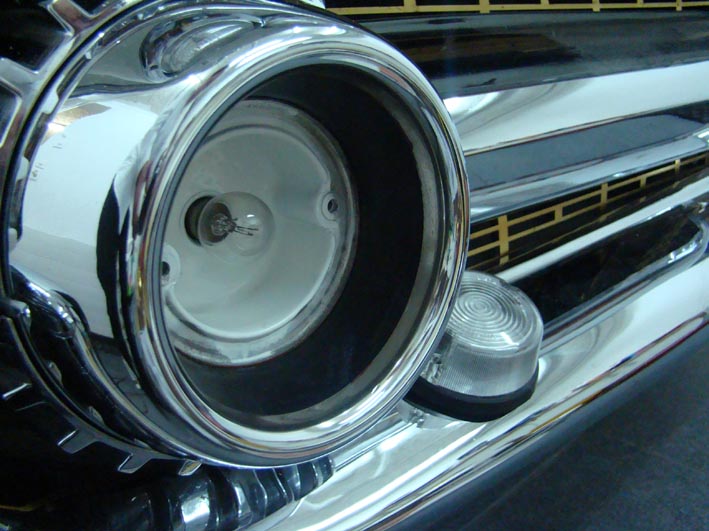
Location: SWITZERLAND | Front Directional Parking Lamps: All the Insiders will have noticed that the Directional Lamps on my 1959 Dodge are not Original. The Lenses were partly broken, the Chrome-Plating on them washed-out and the Bulb Sockets corroded.
Then the Swiss Car Inspection claimed, these Lamps need a viewing angle of minimum 150deg (the bulbs are recessed and not visible from the side). I was committed to add two external Lamp I mounted provisorly with the Side Bumper Bolts - very ugly! Of course, after the Check I removed them.
In addition I could not find replacement Lenses. Recently one NOS went for USD 150.00 on eBay (!). The Reproductions I saw are correct in Shape, but not galvanic rechromed (grey painted), therefore not shiny as the Original. May-be today there are nicer ones. I had to find another Solution.
I purchased Lamps similar to the external Lamps, but with White Lenses. Then my Imagination led me to a Black Silicon Pot, fitting exactly into the rear Side of the Directional Lamps Housing, and sealing in all around without any add-ons. The Lens mounted to be 3mm under the Front Housing, as before not visible from the Side, but performing the Inspections Demand. For a brighter Light I painted ths Inside in white. The Lamp is water-proof, is quite in-line with the Cars Design and looks pretty nice.
 (DSC00040L Old Original Lense.jpg) (DSC00040L Old Original Lense.jpg)
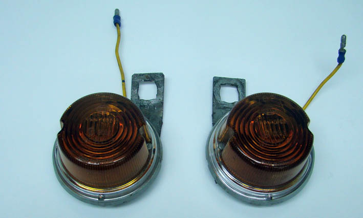 (DSC02315L External Directional Lamps.jpg) (DSC02315L External Directional Lamps.jpg)
 (DSC02317L Silicon Cement Pot.jpg) (DSC02317L Silicon Cement Pot.jpg)
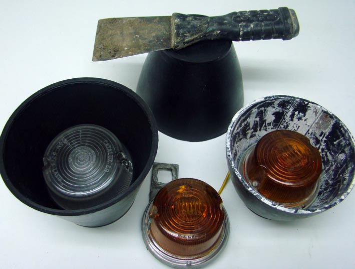 (DSC02326L Items Overview.jpg) (DSC02326L Items Overview.jpg)
 (DSC02329L Interior Lamp.jpg) (DSC02329L Interior Lamp.jpg)
 (DSC00088L New Directional Lamp.jpg) (DSC00088L New Directional Lamp.jpg)
Attachments
----------------
DSC00040L Old Original Lense.jpg (82KB - 902 downloads)
DSC02315L External Directional Lamps.jpg (51KB - 908 downloads)
DSC02317L Silicon Cement Pot.jpg (79KB - 867 downloads)
DSC02326L Items Overview.jpg (75KB - 918 downloads)
DSC02329L Interior Lamp.jpg (95KB - 878 downloads)
DSC00088L New Directional Lamp.jpg (113KB - 913 downloads)
|
|
| |
|
Board Moderator & Exner Expert 10K+
Location: .Norfolk..Mafia.. ,England UK | I have seen the front of your 59 many times on here and NEVER noticed your Front Directional Parking Lamps where altered, They L@@K very nice,,
Keep this thread going, i enjoy reading what you have done, and a few things i may also do to my 59 Coronet..
I,m not too keen on Your Finger Nail Colour Though..........LOL
P.S.. I bought a Pair of NOS Non Genuine lenses a couple years back on US Ebay for $15, They are very close to the Original, Although i have,nt fitted them as mine are good, But the seller listed them as 1958, So no one Bid,, His mistake but my Gain........
Edited by Rebels-59 Coronet 2009-01-03 3:42 PM
|
|
| |
|
Expert
Posts: 1215
Location: SWITZERLAND | Rebels-59 Coronet - 2009-01-03 9:39 PM I have seen the front of your 59 many times on here and NEVER noticed your Front Directional Parking Lamps where altered, They L@@K very nice,, Keep this thread going, i enjoy reading what you have done, and a few things i may also do to my 59 Coronet.. I,m not too keen on Your Finger Nail Colour Though..........LOL P.S.. I bought a Pair of NOS Non Genuine lenses a couple years back on US Ebay for $15, They are very close to the Original, Although i have,nt fitted them as mine are good, But the seller listed them as 1958, So no one Bid,, His mistake but my Gain........ Your remarkable Comment as a 59 Coronet Owner confirms how authentic this Parking Lamp looks. One reason more to copy this in the case of a trouble with the Lenses. These Finger Nails belong to my Stepdaughter (15), I needed a third hand for show the matching Diameter in taking the picture. Not easy, because I have to take care not beeing mirrored in this shiny Chrome. Next time she must change to another Color!
|
|
| |
|
Expert
Posts: 1215
Location: SWITZERLAND | I wrote: "Dual Antenna Gaskets: With my Car I got a complete Set of Rubber Parts. Most of them I could not use, the Gaskets for the Dual Antennas being too big." I just found these new, never used Antenna Gaskets. Now I wanted check if I am not too pedantic, taking a non restored original Antenna Socket as reference. The front Point is adjusted to fit correctly. The rear is about 3mm too long. Judge yourself! In Comparison my Gaskets are "Rolex" for nearly free.
Edited by sermey 2009-01-04 1:29 AM
 (DSC02334L Rear Antenna Rubber1.jpg) (DSC02334L Rear Antenna Rubber1.jpg)
 (DSC02334L Rear Antenna Rubber2.jpg) (DSC02334L Rear Antenna Rubber2.jpg)
Attachments
----------------
DSC02334L Rear Antenna Rubber1.jpg (60KB - 821 downloads)
DSC02334L Rear Antenna Rubber2.jpg (56KB - 762 downloads)
|
|
| |
|
Expert
Posts: 1215
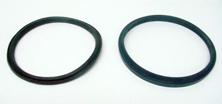
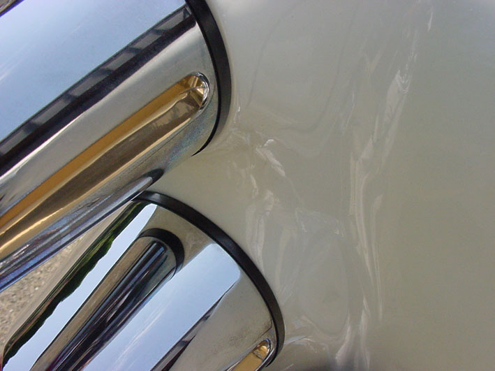
Location: SWITZERLAND | Rear Lamp Gaskets: No comments to the old / original Gasket. I found High Precision Hydraulic Rings, self-centering inside, outside not overlapping at all, and they fit as tailored. The black Height of 1/4" is a nice separation between the White Body and the Rechromed Housing. Another inconspicious "Make-Up".
Edited by sermey 2009-01-03 7:21 PM
 (DSC02339L Old-New Rear Lamp Gaskets.jpg) (DSC02339L Old-New Rear Lamp Gaskets.jpg)
 (DSC02342L New Rear Lamp Gasket Zoomed.jpg) (DSC02342L New Rear Lamp Gasket Zoomed.jpg)
 (DSC00091L New Rear Lamp Gasket.jpg) (DSC00091L New Rear Lamp Gasket.jpg)
 (DSC00090L Left Rear Lamps Housings.jpg) (DSC00090L Left Rear Lamps Housings.jpg)
 (DSC00008L Rear Lamp Gaskets.jpg) (DSC00008L Rear Lamp Gaskets.jpg)
Attachments
----------------
DSC02339L Old-New Rear Lamp Gaskets.jpg (36KB - 782 downloads)
DSC02342L New Rear Lamp Gasket Zoomed.jpg (47KB - 740 downloads)
DSC00091L New Rear Lamp Gasket.jpg (42KB - 782 downloads)
DSC00090L Left Rear Lamps Housings.jpg (82KB - 784 downloads)
DSC00008L Rear Lamp Gaskets.jpg (91KB - 764 downloads)
|
|
| |
|
Walter passed away on Jul 29, 2014. We will miss you, Walt!
Posts: 5358
Location: Heaven Above (Formerly Oklahoma City,OK) | Sermy, I agree with Clive, KEEP this thread going!!! Walt |
|
| |
|
Expert
Posts: 1215
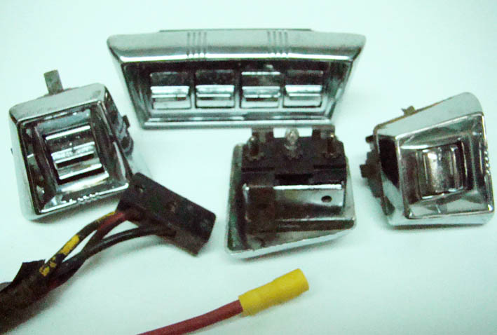
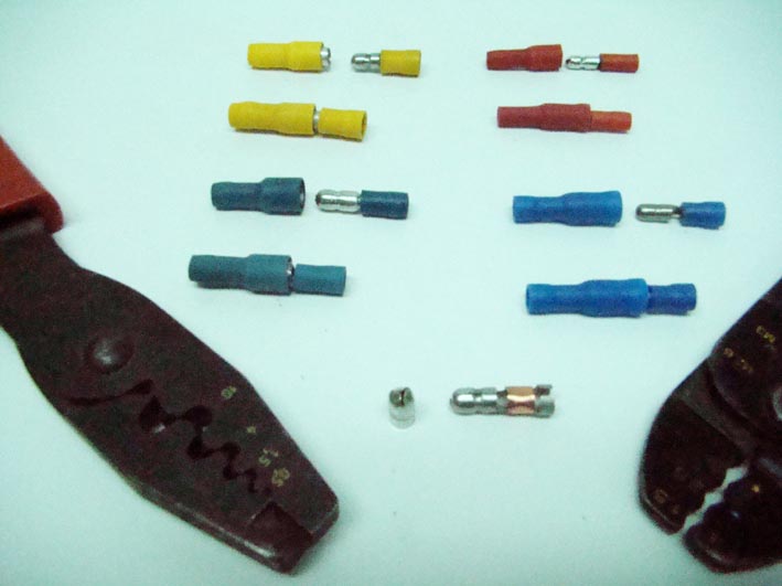
Location: SWITZERLAND | Power Window Switches: These items are very hard to find. And when you have or found them, some Main-Connectors may be missing, often very corroded, bad for a good electrical Contact needed for proper Window lift. Thus, I modificated the single Pin Connectors, also in order to match to the dicker wire in Double Diameter.
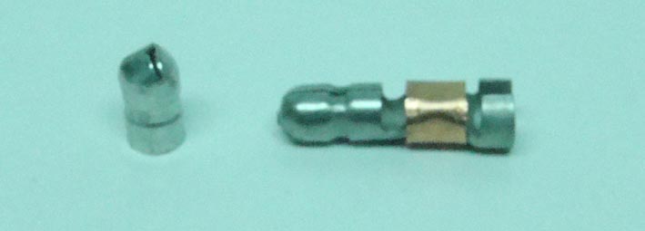
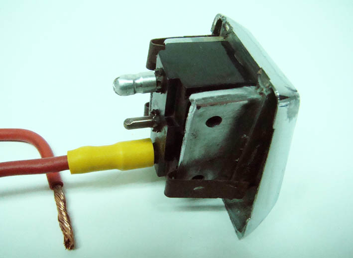
There are many Single Pin Connectors available in Size and in Shape. Round Connectors offer a better electrical Contact due to the bigger surface around the Pin. Here I used the biggest Round one (Yellow). Bonding to the wire it needs a special Handtool, or best is to solder them for best Tensile Strength, especially whe a high flexible Wire is used. Then I cut the Front of the single Male Contacts and soldered them on each Pin of the Power Switch (see picture). Now the Power Window Cables can directly be connected to and removed from the Power Window Switch as any other Cable. The missing or corroded Main Socket is not needed anymore. These Single Cable are of course as before accessible outside the Door Panel, when removing the Switch. Recommended to label the Cables, the + Battery Line always to be Red. This "soldered" Pin Contacting can be used as well on the Instruments Panel.
Edited by sermey 2009-01-04 5:12 PM
 (DSC02361L Power Window Switch Connector.jpg) (DSC02361L Power Window Switch Connector.jpg)
 (DSC02358L Round Pin Connectors.jpg) (DSC02358L Round Pin Connectors.jpg)
 (DSC02359L Cut Male Connector.jpg) (DSC02359L Cut Male Connector.jpg)
 (DSC02365L Soldered Pin & Wire Connected.jpg) (DSC02365L Soldered Pin & Wire Connected.jpg)
Attachments
----------------
DSC02361L Power Window Switch Connector.jpg (70KB - 788 downloads)
DSC02358L Round Pin Connectors.jpg (55KB - 750 downloads)
DSC02359L Cut Male Connector.jpg (26KB - 795 downloads)
DSC02365L Soldered Pin & Wire Connected.jpg (50KB - 764 downloads)
|
|
| |
|
Expert
Posts: 1215
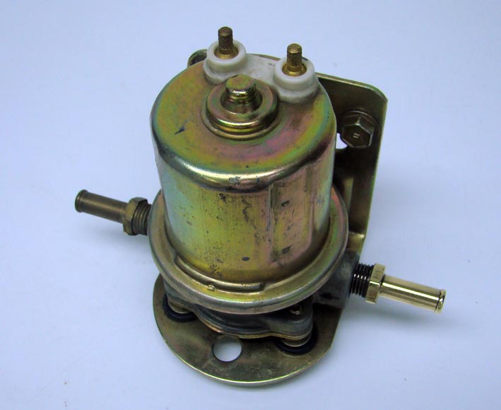
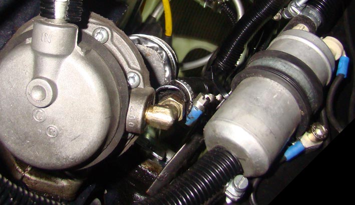
Location: SWITZERLAND | Fuel Pump: Many of you may have encountered the same Situation. You are attending a Car Show, enjoy a nice Day, and are even Candidate for an Award. Later Afternoon you go sitting in your Car, to drive it in to the Ramp or for go Home – many people around watching you and waiting to see the Car drive away. A first attempt to start the car, a second time, a third time again, sometimes until one Minute till running – what a Disgrace in this admired Car!
Firstly I decided to put a Replacement Electric Fuel Pump. Later I thought, one Electric Element more in the Pump risking to fail one day, and remembering my aim to restore at anytime to its Original when I should like. I searched for another Solution: I added a second (electric) Fuel Pump to the already existing (mechanic) Original one in parallel. It is a Round Type with axial Ports, Inlet down-side, Outlet up-side, mounted by a Hose Bracket to the lower Generators Arm. The two Inlets using a Branch Connector (Y) lead to the Fuel Tank Line. Each of the other two Outlets are provided with an one-way Valve before joining together by using another Branch Connector (Y), according the Picture “Fuel Flow Diagram”. The closest +12V ignition-switched Electric Power is diverged from the near Wire leading to the Electric Choke, the Ground (-) to the Bracket Screw. The Picture's View is Down-Up, the second Pump is hardly visible from Top.
To know: As a matter of physical principle, at running engine only one Fuel Pump delivers Fuel to the Carburetor. It's the one generating the higher Pressure, forcing the other Valve to close and avoiding the Fuel to backflow. When one Pump is failing, the other Pump will take over at any instance.
First switch ON the Ignition, listen to the hardly audible buzz of the running Electric Fuel Pump. When the Sound lowers in Frequency means the Carburetor is adequately supplied with Fuel and the Engine ready to start. Can see when the Glass Fuel Filter has no Air anymore. Then go on by switching to the Starter Position. Now, the Car starts immediately at any circumstances. Furthermore, the already activated and thus pre-heated Electric Choke turns the Engine earlier to the lower Idle Speed. Just start and drive away – and happy End of the Car Shows to come!
Edited by sermey 2009-01-05 10:44 AM
 (DSC02376L Replacement Electric Fuel Pump.jpg) (DSC02376L Replacement Electric Fuel Pump.jpg)
 (DSC02375L Fuel Flow Diagram.jpg) (DSC02375L Fuel Flow Diagram.jpg)
 (DSC02372L Dual Fuel Pumps.jpg) (DSC02372L Dual Fuel Pumps.jpg)
Attachments
----------------
DSC02376L Replacement Electric Fuel Pump.jpg (56KB - 809 downloads)
DSC02375L Fuel Flow Diagram.jpg (48KB - 768 downloads)
DSC02372L Dual Fuel Pumps.jpg (78KB - 797 downloads)
|
|
| |
|
Expert
Posts: 1215
Location: SWITZERLAND | Power Windows Lift: This Option I won’t miss on a Convertible, when driving from a Land-Street to the Highway, being exposed all around the Head to heavy wind. At open Top all Windows up reduces the Inside Wind and the arising Noise considerably. On the other side they are a Show Element for Cars at this time.
At Oldtimer Shows you can see many badly aligned and particularly “tired” Power Windows, as very old walking people. The rear Windows are more affected than the Front ones. This difference is mainly due to the longer electrical Wires needed, but also to the Rubber Channel’s Friction they have to overcome, notably the 1957 – 59 ForwardLook Car Versions Convertible and 2-Doors. My ambition was to achieve a Down-Up Time of less than 5 Seconds, and a Window not vibrating in any Position.
After some technical Investigation I came to the Conclusion, that the Original Window Motor, being powered at the lower Limit, could just not meet my demands. I found others, bigger ones, I had to adapt them mechanically. Then I restored the small Window Rollers and all Window Channels.
The Window Channels I squeezed in Height and Width in order to get a clearance of about 1mm to the Rollers. This required a precise alignment to the Doors (Front) and the Body (Rear), so as the Windows could be moved easily by Hand up and down, before installing the Motors. The Channels and Rollers I lubricated with Silicon Grease. The wires I changed to double Diameter and adapted the Pin Connections to the Power Window Switches as already posted earlier, all this for a minimum Voltage Loss due to the Higher Currents. The Main Power Supply I attached at the Convertible Top Switch Unit, after the Thermostatic Interruptor, but before the Top Switch, in order to disconnect the Circuit in Lock Situations or excessive Current drain. Now I could start the first Test: The Windows lifted up and Down like “young Dogs”, achieving my stated goal, but . . . .
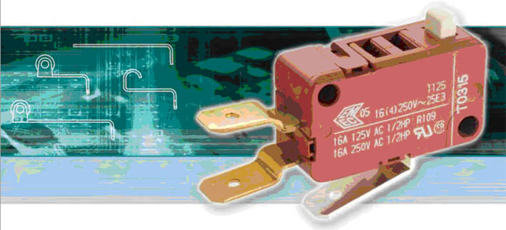
At the lower and upper End, as the Windows are forced to stop by the Stoppers at full Electric Power, the Motor Gear spun risking to damage the Pinion. Fortunately I found the sole correct Solution: at each End, up and down, I mounted a High Current Micro Switch (25A) with a long Lever (Picture from Internet). Instead to adjust the mechanical Stoppers for End Positions, I have accordingly only to bend the Levers of the Micro Switches to stop correctly. Now: - Fine Adjustment and precice Position of the Window at “open” and “closed”. - No excessive Current at Stop, saving the Switch Contacts - No needless mechanical Pression and thus Deformation in the End Positions. - No “stroke with a hammer” at End Stop, but smooth and soundless. - The maximum Down-Up Time is 4 Seconds. - No Time Difference on Rear Window Right, when operated with Main Driver Switch or local Switch (longest wire). But must admit that the Rear Windows upper Edge may injure the Rubber Channel when not aligned and lifting up, due to the Powerful Motor. Edge should be rounded.
(Sorry that could not take Inside Pictures)
Edited by sermey 2009-01-06 5:10 AM
 (Power Micro Switch L.jpg) (Power Micro Switch L.jpg)
 (DSC02378L Windows Left Up.jpg) (DSC02378L Windows Left Up.jpg)
 (DSC02381L Window up Rubber Parallelity.jpg) (DSC02381L Window up Rubber Parallelity.jpg)
 (DSC02383L Front Left Windows Alignment.jpg) (DSC02383L Front Left Windows Alignment.jpg)
 (DSC02379L Rear Right Windows Alignment.jpg) (DSC02379L Rear Right Windows Alignment.jpg)
Attachments
----------------
Power Micro Switch L.jpg (60KB - 806 downloads)
DSC02378L Windows Left Up.jpg (75KB - 776 downloads)
DSC02381L Window up Rubber Parallelity.jpg (70KB - 805 downloads)
DSC02383L Front Left Windows Alignment.jpg (82KB - 776 downloads)
DSC02379L Rear Right Windows Alignment.jpg (66KB - 766 downloads)
|
|
| |
|
Expert
Posts: 1215
Location: SWITZERLAND | Horns: The rechromed Covers in Combination with the painted Body looks great, even at other Colors than Golden. This Improvement makes only sense when the Horns are mounted on the Top as shown. Otherwise they are not visible, and even may disturb the appearing of the Front Grill’s Profile when located behind. In that case the Horns are at best in Black.
 (DSC02386L Chrome Golden Horn.jpg) (DSC02386L Chrome Golden Horn.jpg)
 (DSC02391L Horn Positions.jpg) (DSC02391L Horn Positions.jpg)
Attachments
----------------
DSC02386L Chrome Golden Horn.jpg (84KB - 792 downloads)
DSC02391L Horn Positions.jpg (88KB - 778 downloads)
|
|
| |
|
Walter passed away on Jul 29, 2014. We will miss you, Walt!
Posts: 5358
Location: Heaven Above (Formerly Oklahoma City,OK) | Hi Serge. What kind of fuel pump relay did you install on the electric pump, and did you also install some sort of device to shut off power to the pump in event of collision or other accident? I like electric pumps but I'm concerned about accidents and fire and the electric pump continuing to run on ...... Walt |
|
| |
|
Expert
Posts: 1215
Location: SWITZERLAND | wbower3 - 2009-01-06 4:53 PM Hi Serge. What kind of fuel pump relay did you install on the electric pump, and did you also install some sort of device to shut off power to the pump in event of collision or other accident? I like electric pumps but I'm concerned about accidents and fire and the electric pump continuing to run on ...... Walt Walt, there is no relay nor a shut off switch. The electric pump will be off when the Ignition Switch is set to off. I don't know if a separate (automatic) shut-off is imperatively needed for the case of Collision. I was even not thinking at and never heard about this issue. It's a matter to give some thought to and start a discussion in another thread(?). Thank you for this indication. - SERGE -
|
|
| |
|
Expert
Posts: 1215
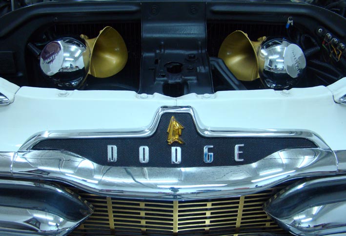
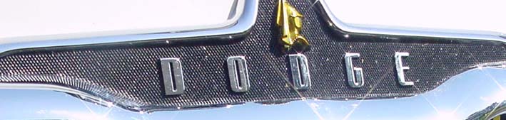
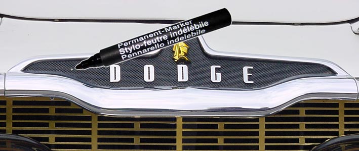
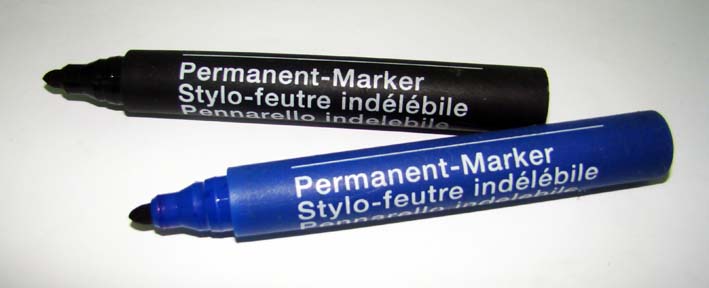
Location: SWITZERLAND | Spot Killer: You have certainly noticed the pure black Color on the Front Medaillon. This didn’t look always as nice, especially after a longer Trip. Color may be partly removed. This happens as well to other painted items of the Car. To remove this Spots “on the Road” just use a standard water-proof Felt Marker. They are available in various Colors and Sizes. If the Color doesn’t match, use the one with the darker note, will be less visible than the brighter one. Always best matched Color: Black is black! This Correction can be useful for the Exterior as for the Interior. It’s a fast way, dries instantly and doesn’t dish up. Thus, keep your Felt Marker always ready in the Car. This is verbally an “applied Make-Up”.
 (DSC00053L Never Spots Killed.jpg) (DSC00053L Never Spots Killed.jpg)
 (DSC00022L Spot Killer.jpg) (DSC00022L Spot Killer.jpg)
 (DSC02419L Water-Proof Felt Markers.jpg) (DSC02419L Water-Proof Felt Markers.jpg)
Attachments
----------------
DSC00053L Never Spots Killed.jpg (43KB - 757 downloads)
DSC00022L Spot Killer.jpg (64KB - 747 downloads)
DSC02419L Water-Proof Felt Markers.jpg (40KB - 765 downloads)
|
|
| |
|
Expert
Posts: 1215
Location: SWITZERLAND | Power Windows Micro Switch: I have found the (broken) Test Switch (25A) and post some Pictures on special Request. The Switch is mounted at the same side as the Window Channels with two Scews, on the left or on the right side, according the Windows side. The Lever is optional (the two small mounting Screws are missing in the Pics). I have added a Side Arm for the Windows Pressing. The Interruption happens within the flexible Range of the Lever, no mechanical Forces on the Switch at all, a smooth Transition. The lower existing original Positioner is to be adjusted just to touch the Windows Edge when stopped. Let there the damping Rubber anyway.
The wires are connected at the Switches sides and fixed with the Screw underneath, as well known from plug connectors. The bigger flexible Wire as showed in "Power Window Switches" is correct for these Holes (tin the Ends).The yellow Meter simulates the Windows Edge, activating the Switch when lifting downwards. By bending the Lever (or moving the Switch) the Stop Position is fine-adjustable. There are two Micro Switches per Window, one for the DOWN and the other for the UP Stop. A simple and reliable Installation, and it works excellent. Good Luck.
Edited by sermey 2009-01-06 11:24 PM
 (DSC02424l Micro Switch No Lever.jpg) (DSC02424l Micro Switch No Lever.jpg)
 (DSC02422L Micro Switch Levers.jpg) (DSC02422L Micro Switch Levers.jpg)
 (DSC02423L Switch Side View.jpg) (DSC02423L Switch Side View.jpg)
 (DSC02425L Wire Connections.jpg) (DSC02425L Wire Connections.jpg)
 (DSC02426L Downward Switching .jpg) (DSC02426L Downward Switching .jpg)
 (DSC02430L Micro Switch Label.jpg) (DSC02430L Micro Switch Label.jpg)
Attachments
----------------
DSC02424l Micro Switch No Lever.jpg (63KB - 733 downloads)
DSC02422L Micro Switch Levers.jpg (68KB - 725 downloads)
DSC02423L Switch Side View.jpg (48KB - 719 downloads)
DSC02425L Wire Connections.jpg (63KB - 724 downloads)
DSC02426L Downward Switching .jpg (35KB - 755 downloads)
DSC02430L Micro Switch Label.jpg (47KB - 730 downloads)
|
|
| |
|
Expert
Posts: 1215
Location: SWITZERLAND | Paint for Horns and Air Cleaner: On special Request. Golden: KRYLON Brass Metallic 2204 (is brighter than the Gold Metallic 1706) Transparent: KRYLON Clear Varnish Coating 7001 To know: The first sprayed brillant Gold will be affected by the transparent Coating. A among many Tests the best Result got with 7001, the 2204 dried out. If not transparent coated the Metallic Surface Brillancy diminishes, even may disappear when cleaning or touching. This second Layer apply at least two times, later it can be polished when get mat.
|
|
| |
|
Expert
Posts: 1215
Location: SWITZERLAND | Power Lock: This is another Feature, as the Power Window Lifts, I won’t miss in my ’59 Dodge. There are various Kits available with all needed items, including the wiring Harness. I saw even Kits including a Remote Control. What you see is a four Door Kit. The Single Units are mounted inside the Door, under the Door Lock, very easy to install. The only Handicap when there is no wiring at all to the Doors. A high flexible, floating Connection.near the lower Door Hinge helps. Thinking ahead I had already provided many supplement Cables when wiring the Power Window Lifts (for Loudspeakers, Power Lock and various Control / Switch Units when required). This Power Lock Option is not visible at all and doesn’t need any exterior Switch. All Doors unlock when the Car is being opened by the Key from Outside, or by the Inside Door Handle (Up). They lock when closing correspondingly. Thus, the Power Locks can be activated from outside at open Windows too by moving the Inside Door Handles up or down. To Know: In this Configuration all Doors have the same State, closed or opened. When disconnecting the Battery and then reconnect, for security reasons, all Locks are turned to the Closed State. Now, not a visible Improvement, but no Problems anymore with a closed Door on the other Side. And it works! (Sorry here again, could not take Pictures from inside)
Edited by sermey 2009-01-07 11:27 AM
 (Power Lock Kit .jpg) (Power Lock Kit .jpg)
Attachments
----------------
Power Lock Kit .jpg (84KB - 719 downloads)
|
|
| |
|
Expert
Posts: 1215
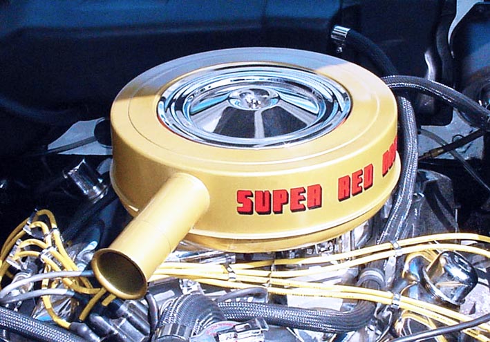
Location: SWITZERLAND | Air Filter: Here the same Color Combination as the Horns. The rechromed Center would fit very well to any other Color.
 (DSC00070L Chrome Golden Air Filter.jpg) (DSC00070L Chrome Golden Air Filter.jpg)
Attachments
----------------
DSC00070L Chrome Golden Air Filter.jpg (118KB - 719 downloads)
|
|
| |
|
Expert
Posts: 1215
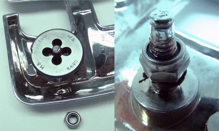
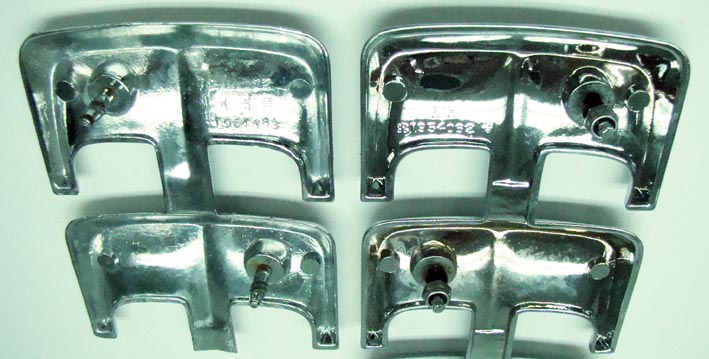
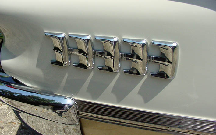
Location: SWITZERLAND | Emblem Studs: In Pot Metal they are damageable when mounting the Emblem using the Self Tapping Nuts another time..And what a Frustration when a Stud go broken! To prevent this I tapped Screw Threadings on any Emblem. Further more it's a smoother feeling to tighten softly.
Sample shown on the Chevron Emblem.
To know: Side Emblems are mostly in Duals as LH and RH. Some of them can be mounted at any Side, when drilling additional Holes. Finding later a NOS Rechromed Chevron, I drilled the additional Holes. Now there are to LH Emblems, not visible at all. Applying this way all 1959 Rear Lamps are interchangeable as well.
Edited by sermey 2009-01-08 5:56 PM
 (DSC02482L Cut Thread.jpg) (DSC02482L Cut Thread.jpg)
 (DSC02477L LH - LR.jpg) (DSC02477L LH - LR.jpg)
 (DSC02475L Symmetric Holes.jpg) (DSC02475L Symmetric Holes.jpg)
 (DSC02470L Mounts Chevron Emblem.jpg) (DSC02470L Mounts Chevron Emblem.jpg)
 (DSC00115L Chevron Emblem.jpg) (DSC00115L Chevron Emblem.jpg)
Attachments
----------------
DSC02482L Cut Thread.jpg (71KB - 733 downloads)
DSC02477L LH - LR.jpg (75KB - 698 downloads)
DSC02475L Symmetric Holes.jpg (17KB - 721 downloads)
DSC02470L Mounts Chevron Emblem.jpg (73KB - 727 downloads)
DSC00115L Chevron Emblem.jpg (66KB - 682 downloads)
|
|
| |
|
Expert
Posts: 1215
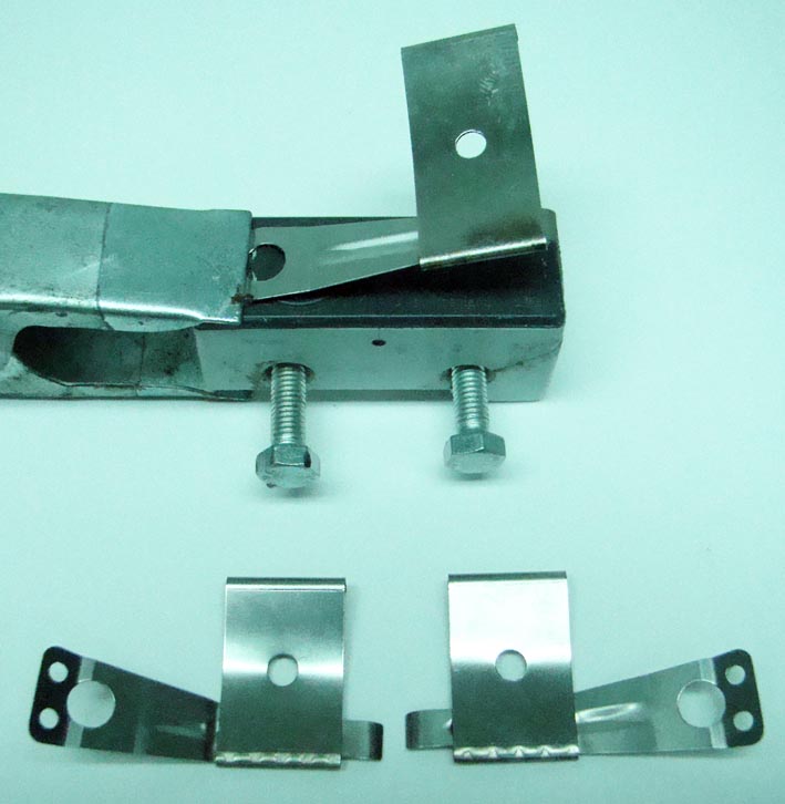
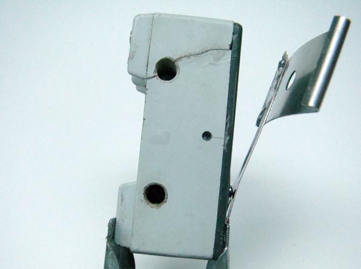
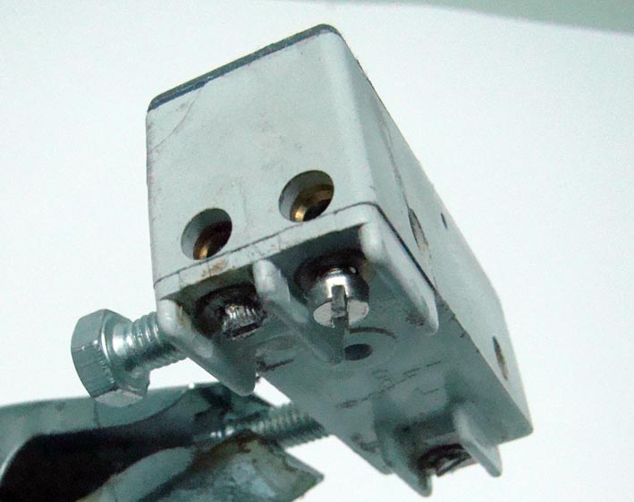
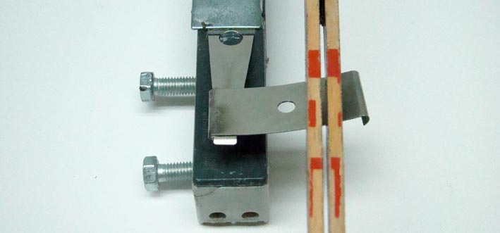
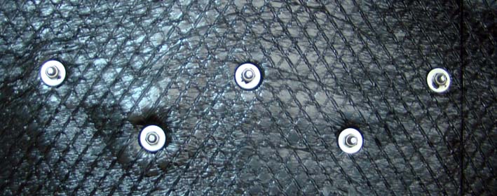
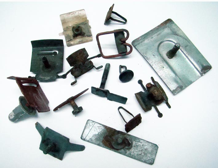
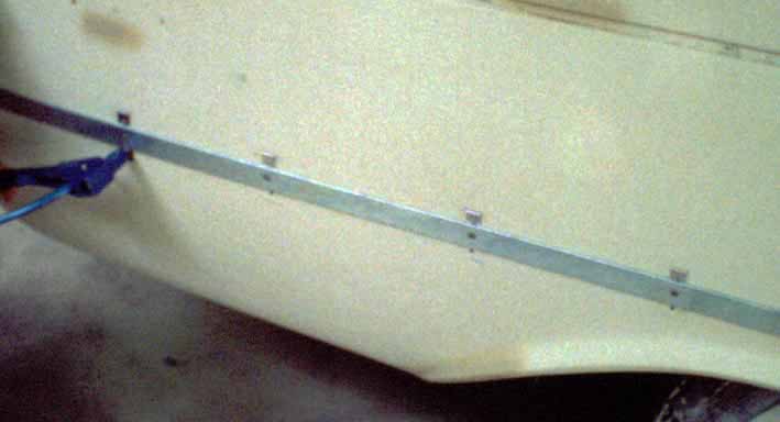
Location: SWITZERLAND | Moulding Clips: As the self-tapping Screws, these items had been designed for a fast Manufacturing, and are not suitable for an outstanding Car. They damage the Paint (as the self tapping Screws), go rusty and don’t tighten the Moulding sufficiently (rattling). The rust is programmed, the Mouldings are loosely and thus not close to the Body. And there should be no Gap at all! I found stainless / rustfree and springy Clips in various Sizes being used to fix Aluminium Covering Profiles. Adding a Screw, attached by soldering (tin), this was the ideal Solution. Now, these are not Clips anymore, but rather Clamps. Inside comes first the Grommet for sealing, then the Washer, and finally the Wing Screw, as well known from the Dual Rear Antenna, for easy fixing by Hand without any Tool. Of course all in stainless / rustfree Metal. By cutting the Sides, they can be fitted to match the Width of any Moulding in the Range, even when the Clips are asymmetric, see “Replacement Sample”. For the Wide Door Mouldings I used two opposed Clips, every 3”, enabling to mount the Moulding from Outside: Down hook in -> push up, and then Up hook in -> push down = Fixed, and adjustable Left < > Right, as Up < > Down due to the Spring Property. They can perfectly be aligned each to other and at any time (see earlier Pictures of the Car) This new Clip is to be tightened till to the Body in benefit to its curved shape and springy Attribute. No loosy Mouldings anymore, no Gaps at all, and last but not least: A very pleasant Assembling.
Edited by sermey 2009-01-08 5:53 PM
 (DSC02439L Various Rusty Clips.jpg) (DSC02439L Various Rusty Clips.jpg)
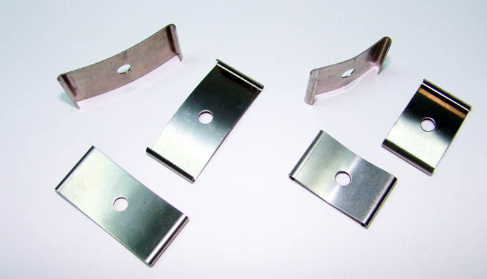 (DSC02444L Clips for Alu-Profile.jpg) (DSC02444L Clips for Alu-Profile.jpg)
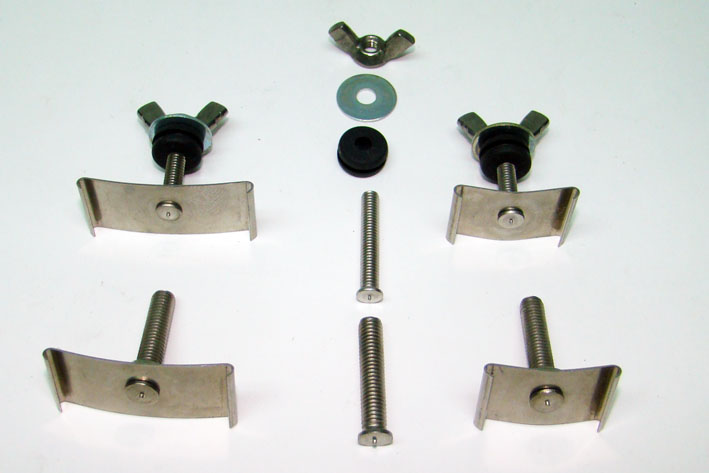 (DSC02445L Clips Assembly.jpg) (DSC02445L Clips Assembly.jpg)
 (DSC02450L Soldered Bolts-Various Sizes.jpg) (DSC02450L Soldered Bolts-Various Sizes.jpg)
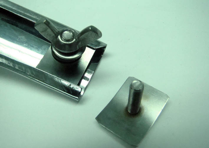 (DSC02488L Application.jpg) (DSC02488L Application.jpg)
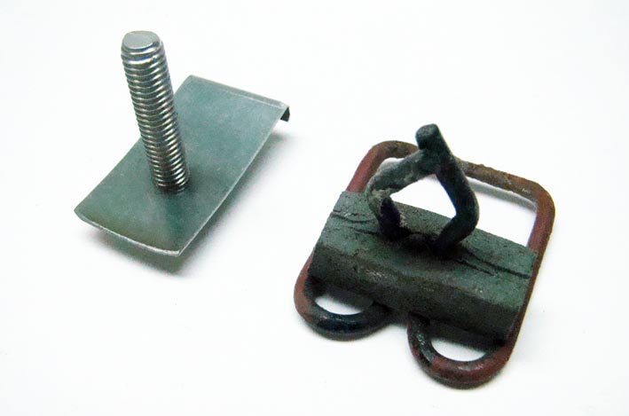 (DSC02489L Replacement Sample.jpg) (DSC02489L Replacement Sample.jpg)
 (DSC02505L Gap Rear Fins.jpg) (DSC02505L Gap Rear Fins.jpg)
 (Riveting Double Clips L.jpg) (Riveting Double Clips L.jpg)
 (DSC02510L Gap Door Moulding.jpg) (DSC02510L Gap Door Moulding.jpg)
Attachments
----------------
DSC02439L Various Rusty Clips.jpg (74KB - 694 downloads)
DSC02444L Clips for Alu-Profile.jpg (43KB - 701 downloads)
DSC02445L Clips Assembly.jpg (52KB - 708 downloads)
DSC02450L Soldered Bolts-Various Sizes.jpg (57KB - 704 downloads)
DSC02488L Application.jpg (50KB - 702 downloads)
DSC02489L Replacement Sample.jpg (44KB - 695 downloads)
DSC02505L Gap Rear Fins.jpg (46KB - 694 downloads)
Riveting Double Clips L.jpg (30KB - 721 downloads)
DSC02510L Gap Door Moulding.jpg (31KB - 685 downloads)
|
|
| |
|
Expert
Posts: 1215
Location: SWITZERLAND | Paunched Sides: All Cars at this time had more or less paunched Sides, best visible from behind along the Car. The Side Mouldings then becomes curved too. A Correction by heating would make it even worse. I tried a mechanical Solution to reduce these Paunches.
In about the Length of the Side Mouldings and under the same Position I mounted Inside a strong Steel U-Profile (W25-H12-D4.5mm). This Dimensions fitted just well behind the Rear Wheelhouse. As expected I didn’t got a straight Line, the max. Curve Retraction was about ¾ “. The Body has become very stiff and highly resistant to Stress.
Paunch reduced - but Weight increased! This is not a Make-Up, rather a Cosmetic Surgery. 
Edited by sermey 2009-01-09 5:27 AM
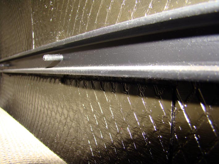 (DSC02459L Profile View Inside Rear Quarter.jpg) (DSC02459L Profile View Inside Rear Quarter.jpg)
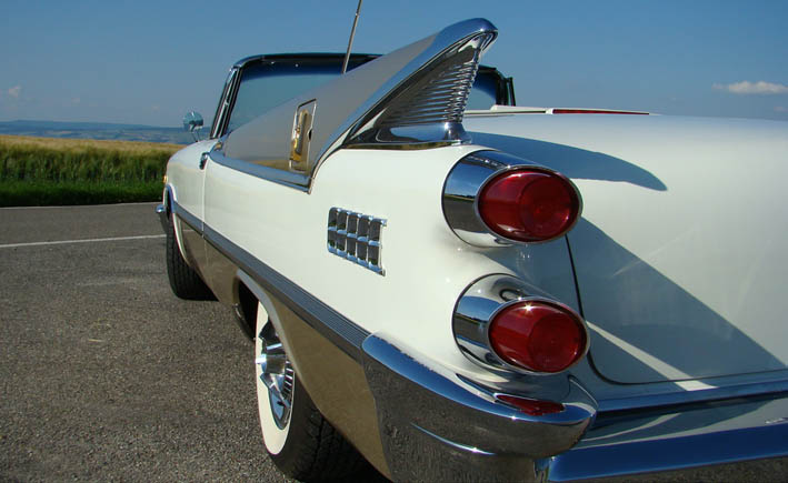 (DSC00221L Rear Side View.jpg) (DSC00221L Rear Side View.jpg)
Attachments
----------------
DSC02459L Profile View Inside Rear Quarter.jpg (87KB - 760 downloads)
DSC00221L Rear Side View.jpg (70KB - 693 downloads)
|
|
| |
|
Expert
Posts: 1215
Location: SWITZERLAND | Dome Light: A visual Gadget is the “Longer Light” Feature. A two Port Electric Box is connected directly to the Dome Light Switch and to Ground, being hidden behind the lower inside Panel, near the Loudspeaker (Pic). For easy Connection remove the Switch and pull the Wires through. To know: This item can as well be connected directly to the Dome Light and the Box hidden behind the Side Panel (Convertible). Attention: Attach to the floating Ground Wire of the Lamp (has 0V when the Lamp is ON) and not to the +12V!!!
Now, closing the Doors the Dome Lights fade out after about 30 Seconds.
Edited by sermey 2009-01-09 8:18 AM
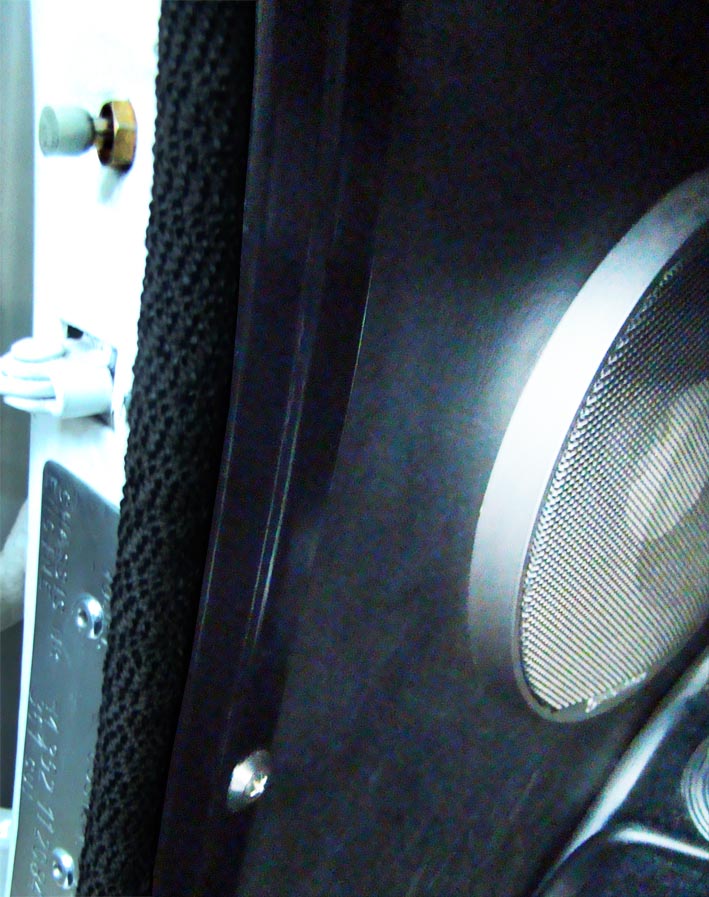 (DSC02514L Dome Light Switch.jpg) (DSC02514L Dome Light Switch.jpg)
 (DSC02515L Dome Light Fading Out.jpg) (DSC02515L Dome Light Fading Out.jpg)
Attachments
----------------
DSC02514L Dome Light Switch.jpg (132KB - 692 downloads)
DSC02515L Dome Light Fading Out.jpg (46KB - 719 downloads)
|
|
| |
|
Expert
Posts: 1215
Location: SWITZERLAND | Trunk Lid: The Problem of the “Half-masted Trunks..” (2006-10-16 /d500neil) has already been discussed. There I showed my Solution using two Gas-Springs, on the left and the right side, needing only two Holes to fix them. The Data and Dimensions are given there. I have already replaced them by the next stronger ones, when I covered the Trunk Lid with the same black Parket as for the Interior. Then the Trunk Lid became heavier, I had simply to replace the Gas-Springs by the next stronger ones. Just take out the Split Pin at the upper and at the lower End, then the Spring Unit can be removed and replaced by another one. This may be important when starting with too weak ones for an exchange where purchased! (the silver Screws fixing the Parket disappear when covered by black Plastic Caps, if prefered)
Now, the Trunk Lid when DOWN remain slightly opened (Trunk Light OFF), or stands UP again as before and in younger Years!
Edited by sermey 2009-01-10 5:06 AM
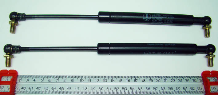 (DSC02497L Gas-Springs Lenght 275.jpg) (DSC02497L Gas-Springs Lenght 275.jpg)
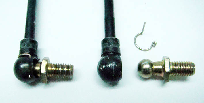 (DSC02516L Snap-On Gas-Spring.jpg) (DSC02516L Snap-On Gas-Spring.jpg)
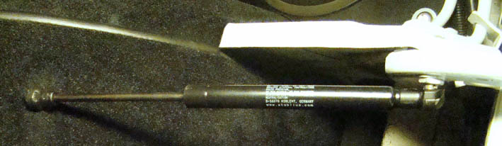 (DSC02495L Front View.jpg) (DSC02495L Front View.jpg)
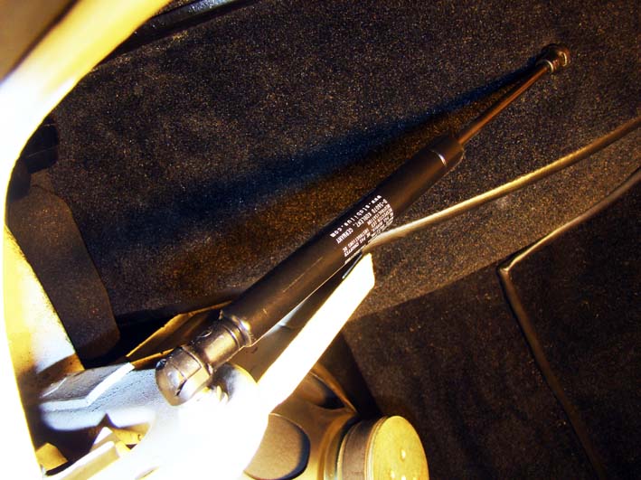 (DSC02496L View Other Side.jpg) (DSC02496L View Other Side.jpg)
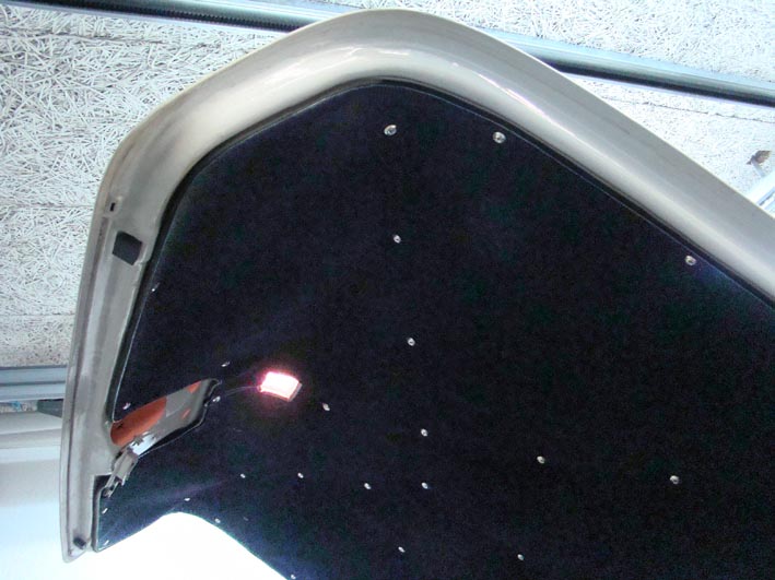 (DSC02522L Interior-Parket on Trunk Lid.jpg) (DSC02522L Interior-Parket on Trunk Lid.jpg)
Attachments
----------------
DSC02497L Gas-Springs Lenght 275.jpg (52KB - 683 downloads)
DSC02516L Snap-On Gas-Spring.jpg (41KB - 675 downloads)
DSC02495L Front View.jpg (45KB - 648 downloads)
DSC02496L View Other Side.jpg (87KB - 686 downloads)
DSC02522L Interior-Parket on Trunk Lid.jpg (82KB - 669 downloads)
|
|
| |
|
Expert
Posts: 1215
Location: SWITZERLAND | Door Weather-Strips: This items on the Car are exposed and visible to anybody, often mounted inaccurately. This stands out on the spot when they are not inline to the opened Window. Usually they are clinched on the Door, not permitting any fine Alignment afterwards. This can be achieved by using Special Screws, flat as Rivets. I found black burned-in Low Profile Pan-Head Screws. Head Height 1.6mm (see on Pic the upper Screw), Diameter 7.8mm, Metric M4x10mm. The Diameter allows a mounting Hole in the Weather-Strips up to 5.5mm for an Alignment Range of over 2mm in any Direction, the low Height make it impossible to touch the Window, and the black Head disappears in the black Strip. Easiest is to use a Manual Hole Puncher for the Strips. First punch 4mm, then more Punches around in order to get the Hole bigger towards the best Position to the Door. Can have more Fixing Points as had before, but should cut at first all Threads in the Door. Now, as well simple and fast to replace them, this when the Strip is wrongly bent at the Ends or too much curved for straightening. (see Alignments of Door Weather-Strips above in Pics “Power Windows Lift”).
Another visible Precision Work on your Car!
Edited by sermey 2009-01-10 4:44 AM
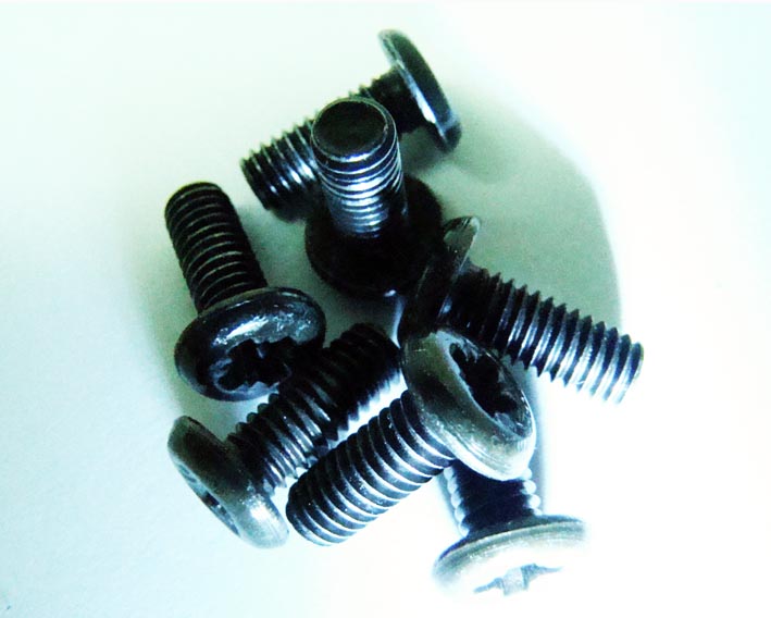 (DSC02531L Low Profile Pan-Head Screws.jpg) (DSC02531L Low Profile Pan-Head Screws.jpg)
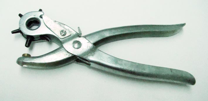 (DSC02532L Manual Hole Puncher.jpg) (DSC02532L Manual Hole Puncher.jpg)
Attachments
----------------
DSC02531L Low Profile Pan-Head Screws.jpg (66KB - 717 downloads)
DSC02532L Manual Hole Puncher.jpg (40KB - 641 downloads)
|
|
| |
|
Expert
Posts: 1215
Location: SWITZERLAND | Slanted Rear Seats: As far I could see, all earlier Convertibles have steeper Rear Seats than the Front Seats. This is uncomfortable to sit and furthermore this looks not inviting. The Front Seats are already steeper then today Cars, the Angle to the sitting Surface cannot be adapted for best feeling, nor with the 6-Way Power Seats Option. With it the entire Seat is rotated front- or backwards.
First I modified the Hinges of the Front Seat for a wider Sitting Angle. Then I moved the Cross Bar of the Rear Back Seat about 2” backward. In the Pics the fomer Original Position is still visible. In Consequence the Rear Seat Mount had moved up, the Bolt is now in an other Position and the Side Panels have been extended accordingly. The needed, interrelated Modifications at the Mechanics of the Convertible Top is reported later. (when you brighten the first Pic you will discover the Steel Profile and the Power Antenna Unit)
Now, a Comfortable Sitting and more Space too for the Rear Passengers, furthermore nice Parallel Back Seats, as well known from 4-Door Cars. All around happy Passengers: Let's lean back and ride.
Edited by sermey 2009-01-10 3:53 PM
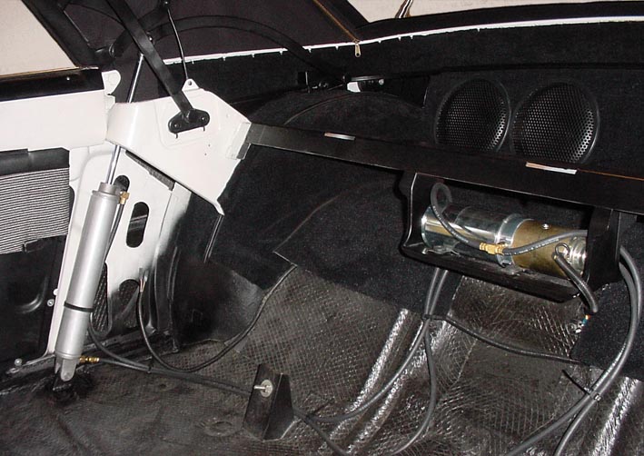 (DSC00058L Overview Behind Rear Back Seat.jpg) (DSC00058L Overview Behind Rear Back Seat.jpg)
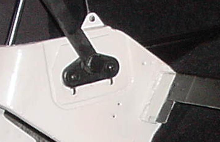 (DSC00058L Zoomed Moved Back Seat Cross Bar .jpg) (DSC00058L Zoomed Moved Back Seat Cross Bar .jpg)
 (DSC00058L Zoomed Moved Back Seat Mount.jpg) (DSC00058L Zoomed Moved Back Seat Mount.jpg)
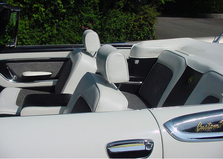 (DSC00051L All Slanted Parallel Back Seats.jpg) (DSC00051L All Slanted Parallel Back Seats.jpg)
Attachments
----------------
DSC00058L Overview Behind Rear Back Seat.jpg (100KB - 678 downloads)
DSC00058L Zoomed Moved Back Seat Cross Bar .jpg (47KB - 704 downloads)
DSC00058L Zoomed Moved Back Seat Mount.jpg (85KB - 690 downloads)
DSC00051L All Slanted Parallel Back Seats.jpg (105KB - 656 downloads)
|
|
| |
|
Expert
Posts: 1215
Location: SWITZERLAND | Drumming Noise: I like Low Noise Cars, can listen to the Music, talk with the Passengers and hear the Birds when driving. In the 50thies they didn’t care about Noise as today.
I found flexible, self-adhesive Panels (50x40x3mm, 5Kg/m2) especially designed to reduce Vibrations, Resonances and this Drumming Noise. Setting them flush one with the other the Surface is waterproof. Except the Engine Compartment, I applied these Panels on any reachable Inside Surfaces: All the Interior, Inside the Doors, over the Rear Axle, on the Rear Wheel Houses, on the Rear Quarters (as already seen in “Paunched Body”), and Inside the Trunk, using total about 5m2 / 25kg. Then comes the black Interior Carpet above all, and finally the Mats tailored as the Originals. (the bright Flash makes the Panels appear in brown)
Now, not only the Drumming Noise is considerably attenuated, but the Doors sound discreet when closing, the covered Ground Surface has a new Look, and driving creates a compact Feeling as in a today Luxury Car. Can say: "Forward (Look) to the Presence!"
Knocking on the Car: "Is it Wood or is it Sheet Metal?". No audible Differences. This is not a “Make-Up” for the Vision, but for the Sense of Hearing.
Edited by sermey 2009-01-11 1:28 PM
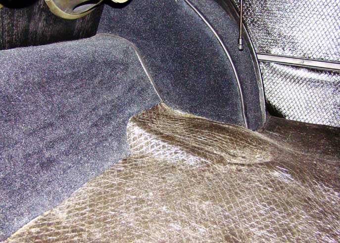 (DSC02641L Covered Rear Wheel House.jpg) (DSC02641L Covered Rear Wheel House.jpg)
 (DSC02642L Four Panels Meet in Trunk.jpg) (DSC02642L Four Panels Meet in Trunk.jpg)
Attachments
----------------
DSC02641L Covered Rear Wheel House.jpg (117KB - 701 downloads)
DSC02642L Four Panels Meet in Trunk.jpg (88KB - 691 downloads)
|
|
| |
|

Expert
Posts: 2598
Location: Upplands Väsby, Sweden | I must say what work you've invested in Dodgen with different solutions. Fun and intresant reading for all of us. Serious work.
Do you have a story about your Dodgen (imported or sold in the new Europe?) How long have you owned it? |
|
| |
|
Expert
Posts: 1215
Location: SWITZERLAND | Joakim, in order not to interrupt this serie I will come back to your questions later on in another thread. -SERGE - |
|
| |
|
Expert
Posts: 1215
Location: SWITZERLAND | Car Protection: An Oldtimer is usually at nicest when the restoration has completed. From now it starts to waste. It should be protected where parked for longer periods, even in a Single Garage. There are many better and more solid Car Covers as the one I use. For Inside Purpose the Cover should absorb sand and dust on both sides, hence no scratches when moving it or hook on the Car; then be partially removable without the need of inter fold, and washable. I found the “Auto-Pyjama”, 100% Cotton and fitting exactly to the Dodge. Cotton in best for polishing, thus the car will rather be polished than scratched when covering, or rubbing the edges. The ’59 Dodge Custom Royal has particularly critical Chrome Edges: the Front Eye-Brows and the Rear Fins. When not covered I protect them by coating with an static-adhesive thin Transparent Foil, well known as used in the Kitchen for Foods. Recommended on long Trips at high Speed too, preventing the Eye-Brows to go sandblasted, as happens to the Windshield. This Foil is as well useful for packaging Spare Parts: they are protected and cognizable, no adhesive Tape needed. Happy to say: After Ten Years since Restoration the Chrome Parts don’t have any Scratches, as the Paint too – the Car has never been polished. Hint: Best Brilliance on Chrome I get with Glass Cleaner (before Photo-Shootings) – shiny as a Mirror, no Tracks left, and as important not removing any Chrome.:) :)
Edited by sermey 2009-01-13 3:14 AM
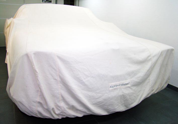 (DSC02644L Dust Protected Car.jpg) (DSC02644L Dust Protected Car.jpg)
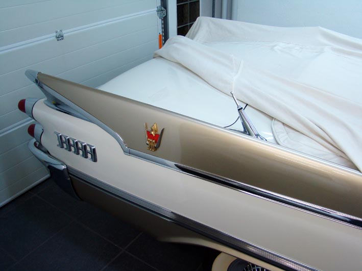 (DSC02648L Discovered Right Rear.jpg) (DSC02648L Discovered Right Rear.jpg)
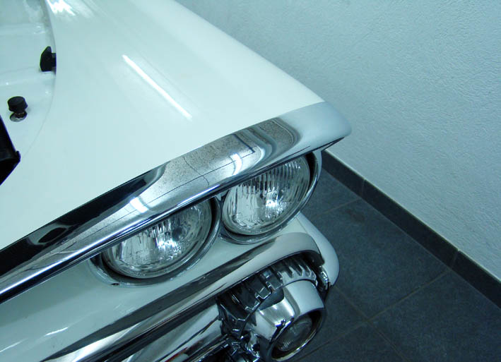 (DSC02655L Shiny Unprotected Eye-Brow.jpg) (DSC02655L Shiny Unprotected Eye-Brow.jpg)
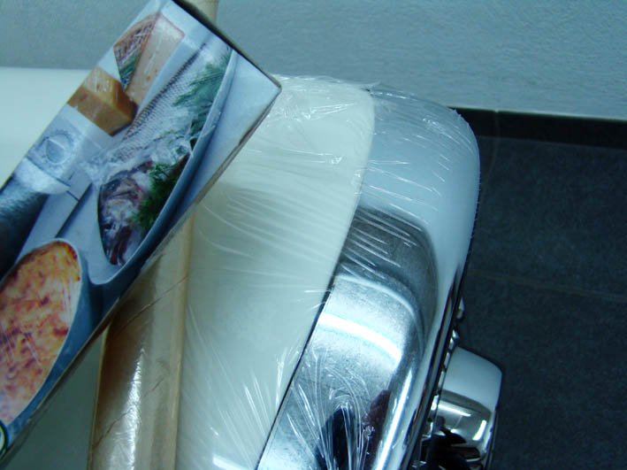 (DSC02668L Foil Protected Eye-Brow.jpg) (DSC02668L Foil Protected Eye-Brow.jpg)
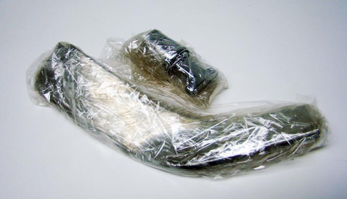 (DSC02666L Foil Packaged Spare Parts.jpg) (DSC02666L Foil Packaged Spare Parts.jpg)
Attachments
----------------
DSC02644L Dust Protected Car.jpg (42KB - 693 downloads)
DSC02648L Discovered Right Rear.jpg (59KB - 725 downloads)
DSC02655L Shiny Unprotected Eye-Brow.jpg (75KB - 702 downloads)
DSC02668L Foil Protected Eye-Brow.jpg (72KB - 692 downloads)
DSC02666L Foil Packaged Spare Parts.jpg (55KB - 690 downloads)
|
|
| |
|
Board Moderator & Exner Expert 10K+
Posts: 13062
Location: Southern Sweden - Sturkö island | This thread is the most interesting lately! Sermey openly shares his innovative and intelligent tricks for to achieve an improvement. Now surely the hard-core OEM guys wont change a thing on their cars, but I will use some of the hints in my car. Thank you Sermey! |
|
| |
|
Expert
Posts: 1215
Location: SWITZERLAND | Thank you Swen. You said correctly as is the rule: "The hard-core OEM guys wont change a thing on their cars". Most "improvements" can easily be restored to its Original, even at the place. Others are not visible at all, many are for the personal comfort and security. But I agree with them: at a glance the Car should show up as Original - and it does when required. On the other side: "The (Car-) Show must go on!" - SERGE -
Edited by sermey 2009-01-13 3:43 AM
|
|
| |
|
Expert
Posts: 1215
Location: SWITZERLAND | Rear Lamps: The Sockets got stainless / rustfree Bolts (M5) fixed by a counter-nut. The assembled Unit is mounted with Wing Nuts (no Tools required). The Lenses got rustfree Thread Screws (M4) too, the Self-Cutting Screws could brake the Lenses locally. As Gasket I used Rubber Sealing O-Rings, leading outside the two Mounting Screws.Two diametric notches have to be grinded as illustrated (Ring: external Diameter 85mm, Thickness 5mm). So, the O-Rings fit and seal as Originals.
I was always fascinated by the broad Rear Lamps on American Cars. As Youngster I could guess the Cars Make at Night, just by their Rear Lights. On my American Cars I wanted more: a Bright Red Glow. I painted the Reflectors from Silver to White, dispersed the Bulbs Light over the Surface of the Lenses, and removed the bright Spot of the Bulbs by a Sticker. On the ‘59 Dodge I wanted a similar Glow Effect.
First I convert the two Back Lights into Stop/Directional Lights by changing the Lenses and the Wiring accordingly. The Back Lights, anyway at the wrong Place for a useable Light, I moved under the Rear Bumpers, in mounting two adjustable, contemporary Chrome Lamps. These Back Lamps gives a wide white Light where needed to see at Night when parking. Beside the Exhaust Outlets I find their aspect nice and discreet (see earlier Pics). To reduce the Spot Effect of the Bulbs I clamped a Light Dispersing Foil inside on the Lenses Surface (Folder available in any Office Shop). Now, the Red Light got a Glowing Effect, another Eye-Catcher at the Night Cruise.
Hint: For a homogenous Red Light the Lenses should be from the same Production Batch.
Edited by sermey 2009-01-13 3:41 PM
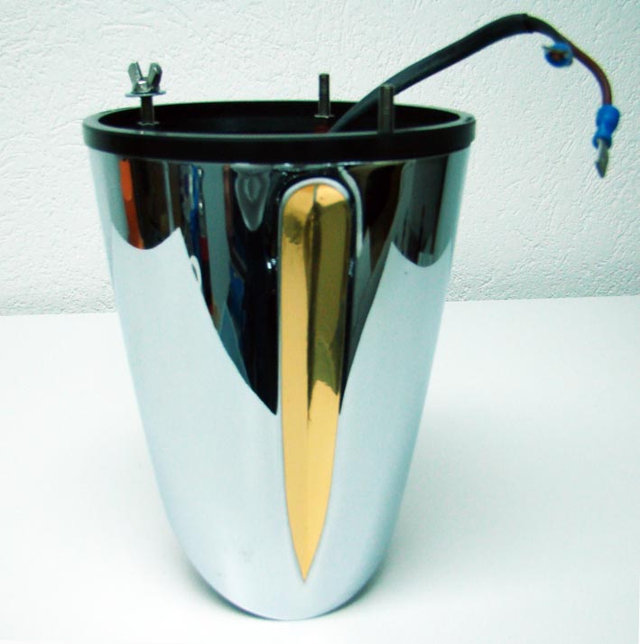 (DSC02693lL Rear Lamp Unit.jpg) (DSC02693lL Rear Lamp Unit.jpg)
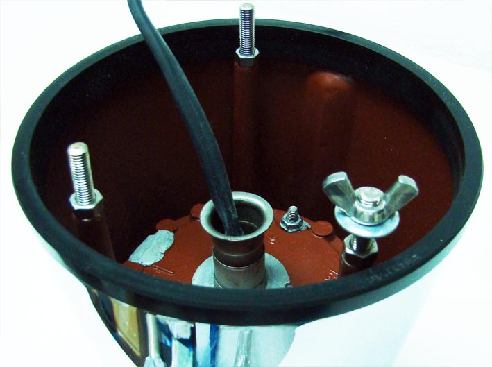 (DSC02691L Zoomed View.jpg) (DSC02691L Zoomed View.jpg)
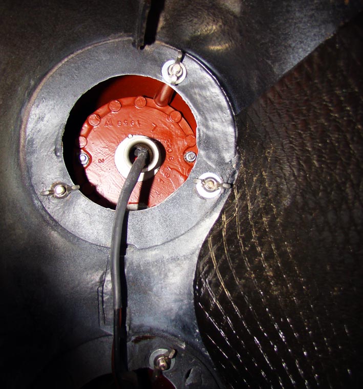 (DSC02684L Rear Lamp Trunk View.jpg) (DSC02684L Rear Lamp Trunk View.jpg)
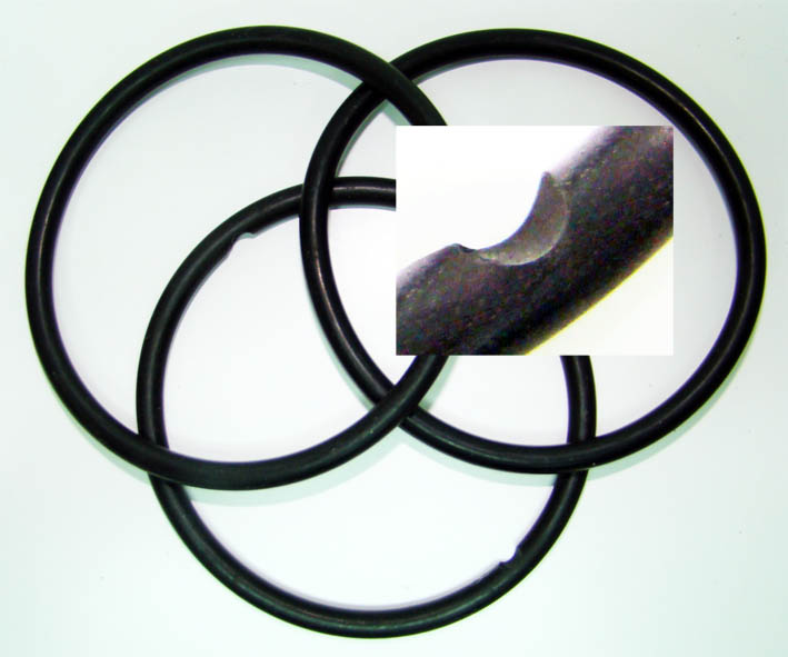 (DSC02703L Notched Seal O-Ring.jpg) (DSC02703L Notched Seal O-Ring.jpg)
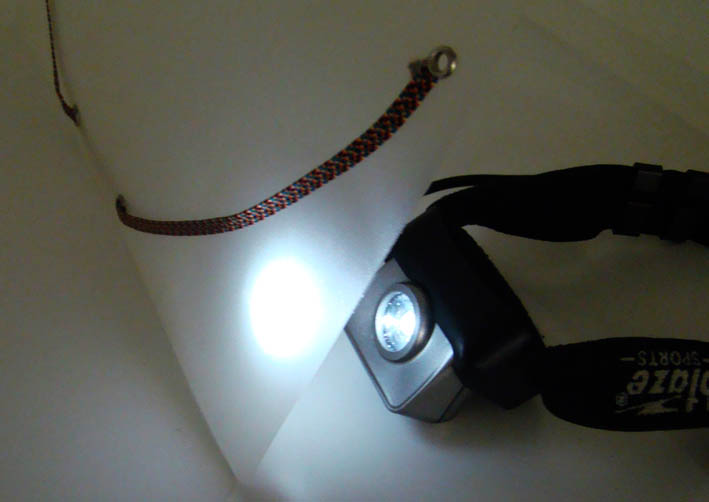 (DSC02707L Dispersion of the Spot.jpg) (DSC02707L Dispersion of the Spot.jpg)
 (DSC02673L Rear Glow.jpg) (DSC02673L Rear Glow.jpg)
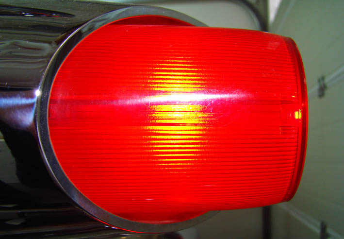 (DSC02677L Zoomed Rear Glow.jpg) (DSC02677L Zoomed Rear Glow.jpg)
 (DSC00023L Bright Stop Light.jpg) (DSC00023L Bright Stop Light.jpg)
Attachments
----------------
DSC02693lL Rear Lamp Unit.jpg (66KB - 699 downloads)
DSC02691L Zoomed View.jpg (68KB - 713 downloads)
DSC02684L Rear Lamp Trunk View.jpg (123KB - 670 downloads)
DSC02703L Notched Seal O-Ring.jpg (66KB - 667 downloads)
DSC02707L Dispersion of the Spot.jpg (43KB - 684 downloads)
DSC02673L Rear Glow.jpg (65KB - 679 downloads)
DSC02677L Zoomed Rear Glow.jpg (70KB - 689 downloads)
DSC00023L Bright Stop Light.jpg (89KB - 687 downloads)
|
|
| |
|

Expert 5K+
Posts: 9787
Location: So. Cal | Very nice effect with the dispersion material. It doesn't seem to dim the overall output at all. Did you put the dispersion material just on the sides of the lens or on the back as well? What did you use to attach it there? |
|
| |
|
Expert
Posts: 1215
Location: SWITZERLAND | Powerflite - 2009-01-13 11:56 PM Very nice effect with the dispersion material. It doesn't seem to dim the overall output at all. Did you put the dispersion material just on the sides of the lens or on the back as well? What did you use to attach it there? About Dim: This is comparable to an opaque and a transparent Home Bulb, both 25W or 40W. Must check for the best Foil, there are various thickness and surfaces.
Attaching: Inside the Lenses the reinforcement for the two screws goes all along. There need two Foils, on one side and on the other side, round bent and just clamped in between. Cut the first “on the job” to lie against the Lenses Inside Surface, then copy all others. On the Back nothing, no considerable improvement. Can put a small white Sticker on Top of the Bulb to remove the bright Spots, see Pic: Bright Stop Lamp. Sorry, could not remove the Lenses for shootings -> fixed and risk to brake.
Edited by sermey 2009-01-14 2:29 AM
|
|
| |
|
Expert
Posts: 1215
Location: SWITZERLAND | Car Height: Lifting or lowering a Car, there are many Opinions and Preferences. It depends on the Car too, and how the Design with the Side Mouldings already influences the Aspect. On the ‘59 Dodge I found best to be about flat, but never lower on the Rear. Thus, I set the Rear to be 3cm Higher than the Front (as all previous Pics), measured on the Side Moulding, Front at their End and Rear over the Wheel. The lowest Front Height was given by the Tires (235/70/15) just not touching the Wheel House when the Steering is fully turned to one Side. With the Air-Controlled Shock Absorbers I could lift the Car to the desired Rear Height. The Air Valve for the setting is intended to be mounted beside the Fuel Port, I left it in the Trunk near the Antenna.
For your own Consideration: I have lifted my Car on the Computer - other Prospects!
Edited by sermey 2009-01-14 11:12 AM
 (DSC02710L Adjustable Shock Absorber.jpg) (DSC02710L Adjustable Shock Absorber.jpg)
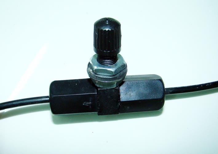 (DSC02728L Air Valve.jpg) (DSC02728L Air Valve.jpg)
 (DSC00044L Rear 3cm Lifted.jpg) (DSC00044L Rear 3cm Lifted.jpg)
 (DSC00044L All Lifted.jpg) (DSC00044L All Lifted.jpg)
 (DSC00044L All Lowered .jpg) (DSC00044L All Lowered .jpg)
 (DSC00044L Rear Lowered.jpg) (DSC00044L Rear Lowered.jpg)
 (DSC00044L Rear Lifted.jpg) (DSC00044L Rear Lifted.jpg)
Attachments
----------------
DSC02710L Adjustable Shock Absorber.jpg (56KB - 705 downloads)
DSC02728L Air Valve.jpg (41KB - 666 downloads)
DSC00044L Rear 3cm Lifted.jpg (70KB - 661 downloads)
DSC00044L All Lifted.jpg (71KB - 697 downloads)
DSC00044L All Lowered .jpg (67KB - 713 downloads)
DSC00044L Rear Lowered.jpg (69KB - 729 downloads)
DSC00044L Rear Lifted.jpg (71KB - 678 downloads)
|
|
| |
|
Expert
Posts: 1215
Location: SWITZERLAND | Removing Pits: When I purchased my Dodge the Pot Metal Parts have been rechromed over the Pits. Fortunately I could interchange all these Parts to a non restored Coronet. The owner was happy to get for free newly rechromed Parts, I too to have the Originals.
When removing Pits it is important that the Geometry remains waveless and as Original. If not, any unevenness will be visible when mirroring. I wanted all my Chrome Parts to be “mirror-proof” and flawless.
I don’t know how others remove Pits, so I did it my way. But first all the Chrome and the Nickel on the items had to be removed (galvanic).
1a Punching with Peening Tool: Take an adjustable Point Puncher and round the Point (3mm). On the Rear Side of the Pit to be removed mark a black Spot (Permanent Marker). Hold the item flat on a hard Wood Surface and punch on the Mark until the Pit has disappeared. Adjust the Puncher Force for at least 5 Punches needed. When the other Side has buckled out about 0.1-0.2mm, the Surface can be leveled by using an ultra fine Rasp (no Abrasives). Then polish, but only when the Geometry is corrected.
1b Spinning with Crusher: This modified Tool is intended for Pits not accessible with the Peening Tool, as some Surfaces under the Eye-Brows. The Rounding and the Height of the interchangeable Steel Nails can be changed as needed. Leveling and polishing as described.
2a Filling with Tin: Chrome and Nickel already removed, let apply a strong Copper Plating. Then put the item on the Cooker (kitchen), adjust the Thermostat to be about 140 Degree, and now with an Electric Tin Solder heath locally until melting, applying flux and tin (0.3mm /180deg, as used for micro electronics) just as much as needed to fill the Pit. Then remove the Solder instantly and go to the next Pit. When all is done, level the Surface as described, and copper-plate for the Finish. 2b Filling with Paste: As in 2a, the Surface needs a Replating with Copper to be cleaned in the Pits. Then, instead of Tin, fill the Pits with a electrical conductive Paste (3M), similar as used for rechroming Plastics and proceed as decribed. Microscopic best I found the first three Methods when possible, because of the all Metallic Transition. In some cases a Combination of them is needed. Once started and experienced with, it worked better than imagined. The final Brilliance of the item, when Nickel and Chrome plated, is given by the polishing of the last Copper Plating. This is most important Section for a brillant track-free Chrome. For that reason I have polished myself all Parts. For the Rear Lamp Sockets I did an Adapter to mount them on the Drilling Machine for grinding out thes many Pits. These maNot having Internet and eBay at this time I could not buy NOS Parts. Even these Parts are mostly minor pittet and have to be restored. Anyway, a good and friendly Relationship with the Galvanic Man is required.
The Chrome Parts on the Pics above show how the Geometry is restored to its Original, a flat undistorted mirroring surface all around!
Edited by sermey 2009-01-16 2:10 AM
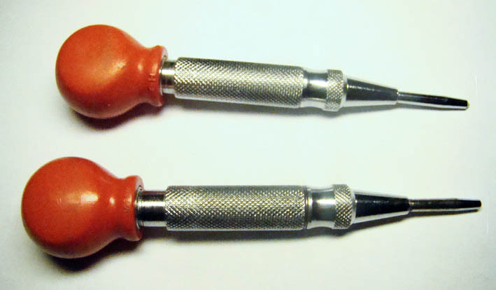 (DSC02738L Adjustable Punch Markers.jpg) (DSC02738L Adjustable Punch Markers.jpg)
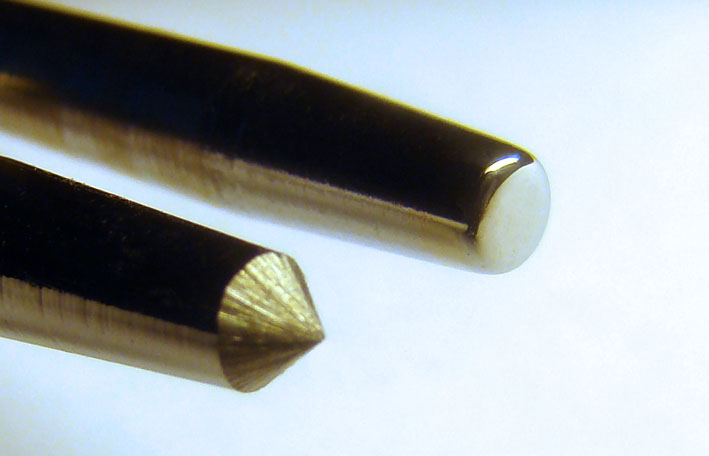 (DSC02734L Pointed & Rounded.jpg) (DSC02734L Pointed & Rounded.jpg)
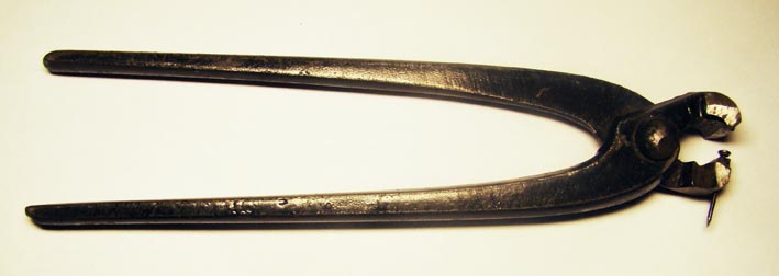 (DSC02743L Modified Crusher.jpg) (DSC02743L Modified Crusher.jpg)
 (DSC02742L Inserts Roofing Nails.jpg) (DSC02742L Inserts Roofing Nails.jpg)
 (Rear Emblem L.jpg) (Rear Emblem L.jpg)
 (Side Moulding L.jpg) (Side Moulding L.jpg)
 (Rear Lamp Sockets L.jpg) (Rear Lamp Sockets L.jpg)
Attachments
----------------
DSC02738L Adjustable Punch Markers.jpg (51KB - 694 downloads)
DSC02734L Pointed & Rounded.jpg (52KB - 646 downloads)
DSC02743L Modified Crusher.jpg (34KB - 713 downloads)
DSC02742L Inserts Roofing Nails.jpg (49KB - 697 downloads)
Rear Emblem L.jpg (61KB - 669 downloads)
Side Moulding L.jpg (81KB - 679 downloads)
Rear Lamp Sockets L.jpg (81KB - 687 downloads)
|
|
| |
|
Expert
Posts: 1215
Location: SWITZERLAND | Directional Flasher: It had happened to me some times, driving in my Topless Convertible to the Highway, and the activated Directional Flasher not turned off. Because of the bright Sunlight I neither could see the Green Flashing Lamps on the Instruments Panel, nor could hear the Flasher switching under the Dashboard due to the Streets Noise. 1. I connected a Miniature Buzzer (+12V) to the Input Port (red) and Output Port (blue) of the Directional Flasher. This Flasher Output leads to the Directional Switch on the Steering Wheel, and then to the corresponding Lamps, left or right. The Buzzer will sound anytime when the Flasher Switch is open and the Directional Switch ON, means in opposite Cycle as the Lamps. When an electronic Flasher Unit (not a bi-metal) in used, then connect the Buzzer to the Output Port of the Flasher (red) and to the Ground (blue).
2. The Buzzer can directly be attached to both Wires leading to the Directional Lamps too. Because it is a DC (Direct Current) Device, a Full Wave Rectifier (50V/200mA or higher)) must be pre-connected. It turns the Supply Voltage in any Direction to the correct Polarity. Even when there is one commun Bulb for Directional and Brake, as most Cars had at this time, the Buzzer will sound only when only one Side is ON. Thus when braking there is no Voltage across the two Wires of the ON Lamps, and of course no buzzing.
The Loudness is adjusted acoustically by wrapping something around the Buzzer and / or by hiding it under the Dashboard. To know: the bi-metal Flasher is short-circuit at no Current.
Now, the Buzzer produces a well-known intermitting alert, audible even in noisy ambient, no need to check the Instruments Panel, a relaxed Concentration on the Traffic.
Edited by sermey 2009-01-17 2:00 AM
 (DSC02784L Rectifier & Buzzer.jpg) (DSC02784L Rectifier & Buzzer.jpg)
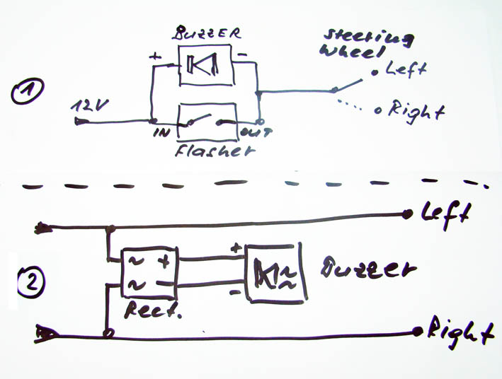 (DSC02785L Wiring Diagram.jpg) (DSC02785L Wiring Diagram.jpg)
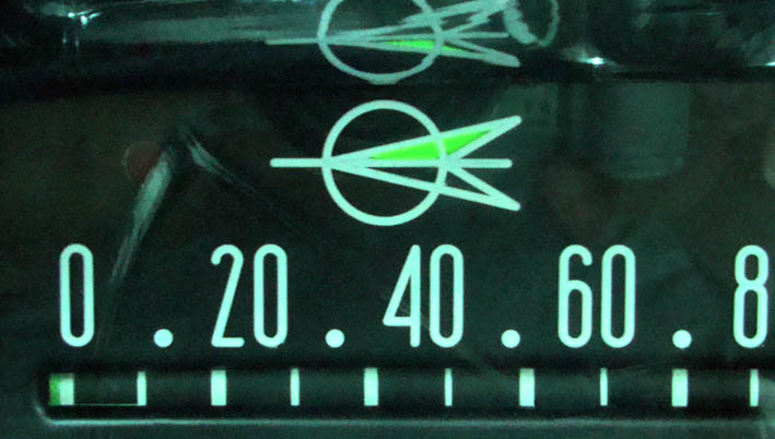 (DSC02747L Left Directional Light ON.jpg) (DSC02747L Left Directional Light ON.jpg)
Attachments
----------------
DSC02784L Rectifier & Buzzer.jpg (58KB - 733 downloads)
DSC02785L Wiring Diagram.jpg (68KB - 722 downloads)
DSC02747L Left Directional Light ON.jpg (63KB - 737 downloads)
|
|
| |
|
Expert
Posts: 1215
Location: SWITZERLAND | Rear Center Brake Light: The new four glowing Rear Lamps instead originally two of them I still found insufficient for a Show-Effect, namely at Night. The next way was to add a Center Brake Light. The demands on this Feature, should: - match to the body in Size and Color as designed for - be easy to remove at anytime and at the place - not leave any Marks when taken off - show an intense Red Light in the same shade as the other Rear Lamps. Among many offered Kits I selected the best matching one.I lowered the Lamp Unit by removing the bottoms Body, attached two springy mounting Brackets in thin Stainless Steel inside connected to the Minus of the Bulbs, and then painted the Body in the Cars Color.
The Lamp Unit is fixed by two Screws for the Tops Cover. The springy Pression of the Brackets hold it tight on the Cars Surface. Pushing by side the Center Chrome Coupling of the Mouldings there is access to the single wire leading to the Rear Brake Lamp, as Power Supply. To know: When there is a combined Lamp for Directional and Brake, as most Car had at this time, then the Supply should be branched directly to the Brake Light Switch. Now, all initial demands could be completed. This additional Feature is another attractive Eye-Catcher and improves the Cars Show-Effect by an exciting Red Glow when braking. Another item instantly removable to its Original! (my Digital Camera doesn’t like this high Contrast Bright Red!)
Edited by sermey 2009-01-17 1:30 PM
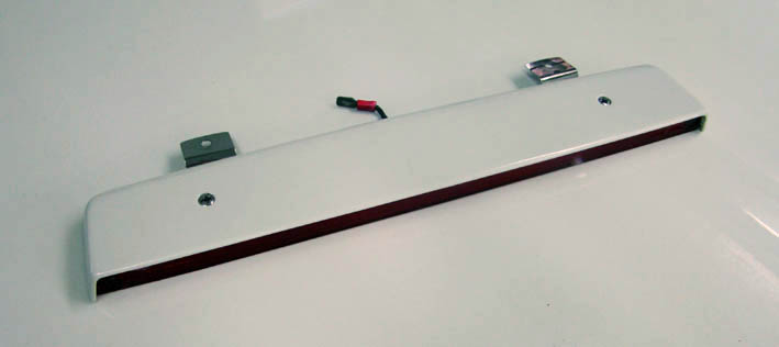 (DSC02803L Brake Light Unit Top View.jpg) (DSC02803L Brake Light Unit Top View.jpg)
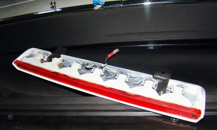 (DSC02799L Brake Light Unit Rear View.jpg) (DSC02799L Brake Light Unit Rear View.jpg)
 (DSC02804L Brake Light Unit Ready for Mount.jpg) (DSC02804L Brake Light Unit Ready for Mount.jpg)
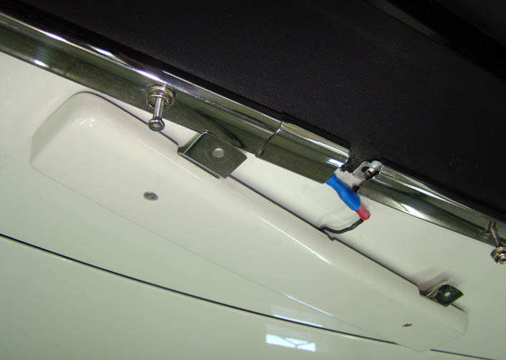 (DSC02794L Brake Light Unit Connected.jpg) (DSC02794L Brake Light Unit Connected.jpg)
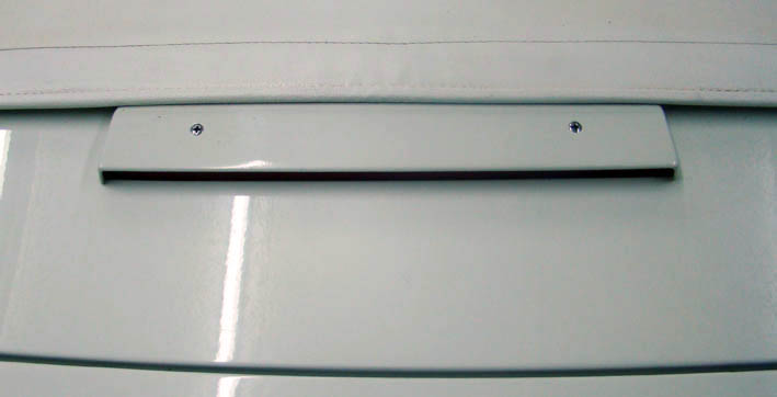 (DSC02788 Brake Light Unit Mounted.jpg) (DSC02788 Brake Light Unit Mounted.jpg)
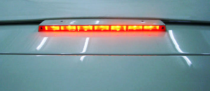 (DSC02786L Center Brake Light ON.jpg) (DSC02786L Center Brake Light ON.jpg)
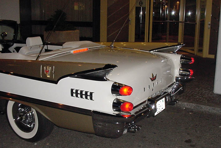 (DSC00001L Brake Lamps Side View.jpg) (DSC00001L Brake Lamps Side View.jpg)
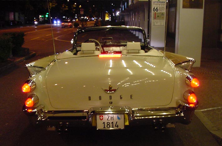 (DSC00007L Night Lights.jpg) (DSC00007L Night Lights.jpg)
Attachments
----------------
DSC02803L Brake Light Unit Top View.jpg (28KB - 693 downloads)
DSC02799L Brake Light Unit Rear View.jpg (62KB - 744 downloads)
DSC02804L Brake Light Unit Ready for Mount.jpg (38KB - 735 downloads)
DSC02794L Brake Light Unit Connected.jpg (54KB - 715 downloads)
DSC02788 Brake Light Unit Mounted.jpg (33KB - 738 downloads)
DSC02786L Center Brake Light ON.jpg (45KB - 711 downloads)
DSC00001L Brake Lamps Side View.jpg (79KB - 709 downloads)
DSC00007L Night Lights.jpg (71KB - 705 downloads)
|
|
| |
|
Expert
Posts: 1215
Location: SWITZERLAND | Tag Plate: On a nice Car the License Plate should be as nice, for most people look at this. The Expert however is interested in the Tag Plate. This Plate is as the Birth Certificate of the Car, an important integral Part and merits to be cared. What a Problem when this Plate is missing, I just read in another Thread! When restoring a Car, many paint over the Tag Plate. Made in Aluminum, a polishing gives an additional decorative Character. It can be anodized in any Colors as illustrated. This Golden would better match to another Paint. (the lower Shadow is the Hood Reflection). For a fix mount I used Aluminum Rivets instead of Screws, polished too. Small effort, nice Effect.
Now, at the first glance the Expert will get an excellent Impression of the Car, the next Look at the Tag Plate he will be positively surprised!!
Edited by sermey 2009-01-18 12:31 PM
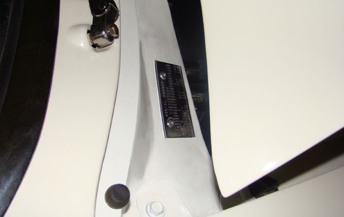 (DSC02817L Tag Plate.jpg) (DSC02817L Tag Plate.jpg)
 (DSC01376L Polished Tag Plate.jpg) (DSC01376L Polished Tag Plate.jpg)
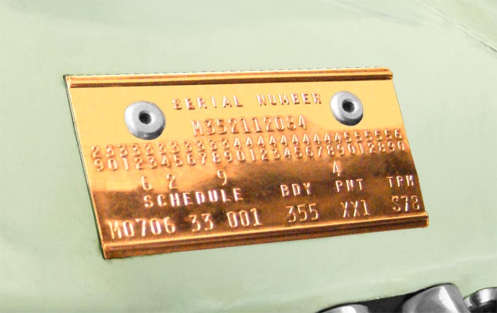 (DSC01376L Anodized Tag Plate.jpg) (DSC01376L Anodized Tag Plate.jpg)
Attachments
----------------
DSC02817L Tag Plate.jpg (48KB - 710 downloads)
DSC01376L Polished Tag Plate.jpg (46KB - 711 downloads)
DSC01376L Anodized Tag Plate.jpg (59KB - 692 downloads)
|
|
| |
|
Expert
Posts: 1215
Location: SWITZERLAND | Hood Isolation: Many Hoods comes with poor or even with no Isolation at all. Knocking on the Hood is an acoustical Check how the Hood is isolated. Isolation means damping of Drumming due to Vibrations and Motor Noise, but will isolate from Heath too. I put an Isolation of a today Car, usually made in one piece, for they are heath resistant and attenuate the Noise considerably. To keep the Design of the Under Hood the Isolation is cut in Segments to fit in and then glue them on. Take your attention to the upper Rubber Strip. This prevents hot Air Circulation from the Engine Compartment turning back to the Cooler when the Car stands idling. (the white shadows are sunshine reflections of the Air Cleaner and others)
Must see and hear the Difference!
Edited by sermey 2009-01-21 10:46 AM
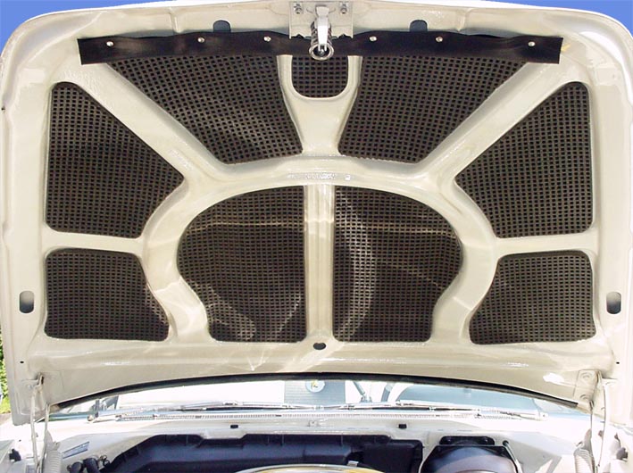 (DSC00069L Hood Isolation.jpg) (DSC00069L Hood Isolation.jpg)
Attachments
----------------
DSC00069L Hood Isolation.jpg (109KB - 707 downloads)
|
|
| |
|
Expert
Posts: 1215
Location: SWITZERLAND | Radiator Cap: Many small polished items enhance the Status of a Car. Here some visible Distinctions more. Just to see.
Edited by sermey 2009-01-21 4:02 PM
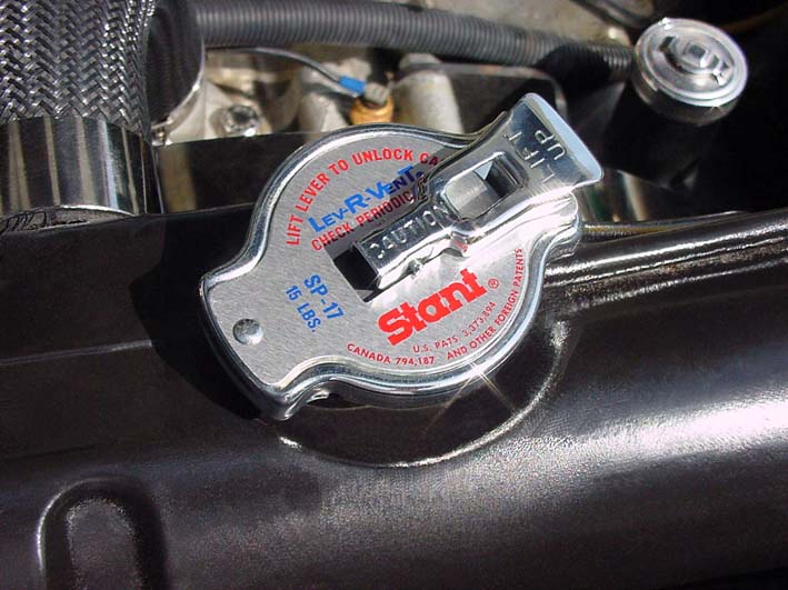 (DSC00079L Polished Radiator &-Steering Pump Cap.jpg) (DSC00079L Polished Radiator &-Steering Pump Cap.jpg)
Attachments
----------------
DSC00079L Polished Radiator &-Steering Pump Cap.jpg (86KB - 728 downloads)
|
|
| |
|
Expert
Posts: 1215
Location: SWITZERLAND | Convertible Top: A white Top is nice for any Bodys Color – except for white. Because Top and Body in white never match exactly, one will always appear as dirty. Thus, I switched to a black Top, matching best to my black/white Interior. Due to the slanted Rear Back Seats I had to do minor Modifications on the Tops Mechanic. Simultaneously I lowered it for Top DOWN Position, to reduce the old fashioned “carriage” Look. By modifying the arms in shape, length and crops, the Mechanics went considerably lower, resulting only +1.5cm to the Height of the Body Sides with mounted Top (see earlier Pics of the Car too). As the Picture shows, now there is just enough room for the Top behind the slanted Rear Back Seats.
Modified, complementary croped Arms for lowering the Mechanics are illustrated. The left and the right side Arms must have identical mirrored shape. To protect the Top, all Edges of the Main Arms are rounded (for the finish use abrasive paper at Top UP). Customized Stainless Screws and Nylon Bushings with borders (to put between the Arms) assure a frictionless, inaudible and smooth Operation, no needing oil lubrication. Another functional and visible improvement!
To know: Important for lowest Top DOWN and minor Wrinkles is a carefully correct folding. This needs about 2 – 3 Steps. The Vinyl Window I left always closed at Top DOWN. Without Top and the Cylinders disconnected, the Mechanics should be moved easily up and down by hand. The Top DOWN Height then is lower than the Body Sides.
Edited by sermey 2009-01-25 4:49 PM
 (DSC02856L Modified Top Screws and Bushings.jpg) (DSC02856L Modified Top Screws and Bushings.jpg)
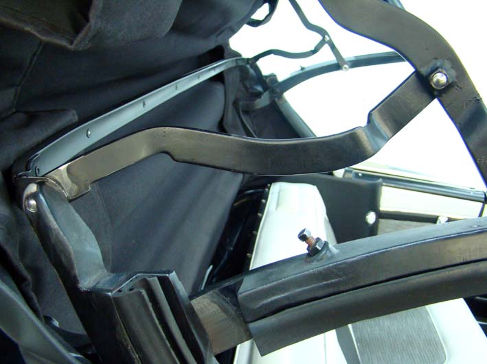 (DSC02849L Modified Croped Arm.jpg) (DSC02849L Modified Croped Arm.jpg)
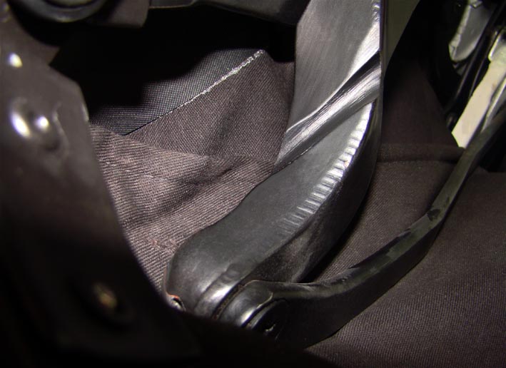 (DSC02936L Other Side Main Arm Crop.jpg) (DSC02936L Other Side Main Arm Crop.jpg)
 (DSC02851L Top Lifted.jpg) (DSC02851L Top Lifted.jpg)
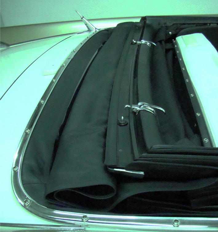 (DSC02825L Top DOWN Folded.jpg) (DSC02825L Top DOWN Folded.jpg)
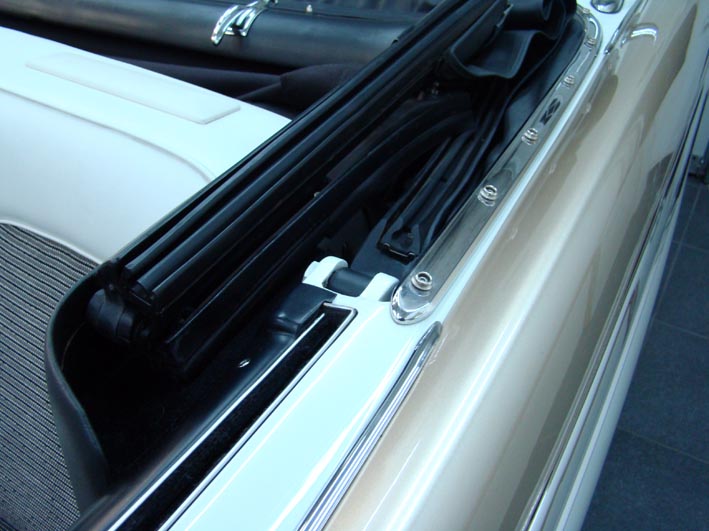 (DSC02828L Top full DOWN in Side Panel.jpg) (DSC02828L Top full DOWN in Side Panel.jpg)
 (DSC00082L Lowered Top Covered.jpg) (DSC00082L Lowered Top Covered.jpg)
 (DSC00096L Top Up Back View.jpg) (DSC00096L Top Up Back View.jpg)
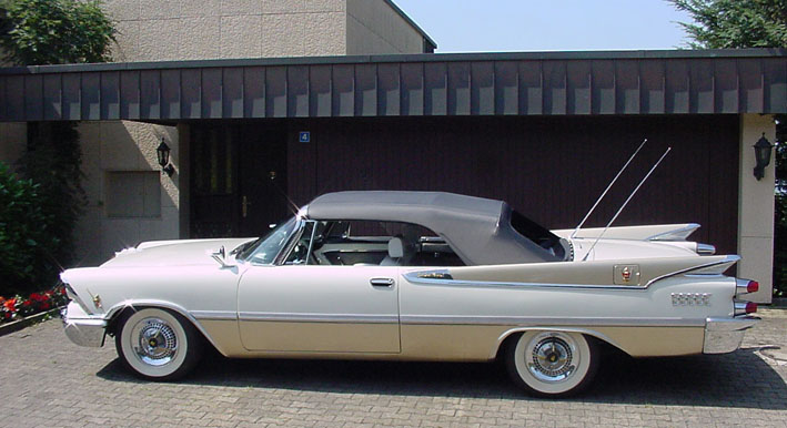 (DSC00094L Top UP.jpg) (DSC00094L Top UP.jpg)
Attachments
----------------
DSC02856L Modified Top Screws and Bushings.jpg (63KB - 724 downloads)
DSC02849L Modified Croped Arm.jpg (66KB - 660 downloads)
DSC02936L Other Side Main Arm Crop.jpg (72KB - 663 downloads)
DSC02851L Top Lifted.jpg (64KB - 691 downloads)
DSC02825L Top DOWN Folded.jpg (89KB - 702 downloads)
DSC02828L Top full DOWN in Side Panel.jpg (82KB - 697 downloads)
DSC00082L Lowered Top Covered.jpg (54KB - 680 downloads)
DSC00096L Top Up Back View.jpg (96KB - 721 downloads)
DSC00094L Top UP.jpg (86KB - 702 downloads)
|
|
| |
|
Expert
Posts: 1215
Location: SWITZERLAND | Fuse Box: When I switched from the Generator (30A) to an Alternator (60A) it was obvious to install two new Fuse Boxes. I went sick to search the hidden Fuses under the Dashboard for a replacement, not seeing anything. Then I changed the Wires to double Diameter. The new Fuse Boxes use Color encoded Fuses, easy to remove with the special Tool. I mounted them on the left front Wheelhouse for direct access, first both on a metal bar, then this unit with two longer screws from center to the body, as can see on the last Pic. All "fused" cables leading underneath invisible to the thick Wire Channel, then to the Instruments Panel. The transparent Covers with Rubber Seals make them water proof and allow an instant visual Check of the Fuses. The One-Wire Alternator allow a simple wiring: from the Alternator to the First Fuse Box, then leading the wire (yellow) through the Ampere Gauge in the Instruments Panel, then back (red) to the Second Fuse Box, and finally ending at the Battery (+). The First Box supplies all items needed to be measured, the second one the momentary High Current items directly from the Battery, not measured such as Starter, Power Windows, Convertible Top, needing Fuse Values up to 40A. The new Voltage Regulator is still there but not connected. Now, at a "Black-Out" by a defective Fuse: just lift the Hood, look at the Fuses and replace the defective one!
Edited by sermey 2009-01-26 8:29 AM
 (DSC02890L One Wire Alternator.jpg) (DSC02890L One Wire Alternator.jpg)
 (DSC02967L Wiring Diagram.jpg) (DSC02967L Wiring Diagram.jpg)
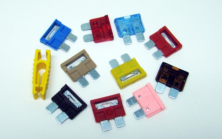 (DSC02963L Tool & Color Coded Fuses.jpg) (DSC02963L Tool & Color Coded Fuses.jpg)
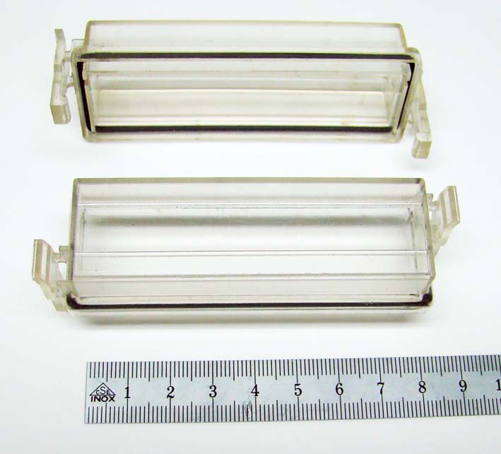 (DSC02966L Rubber Sealed Fuse Box Covers.jpg) (DSC02966L Rubber Sealed Fuse Box Covers.jpg)
 (DSC02959L Opened Fuse Boxes.jpg) (DSC02959L Opened Fuse Boxes.jpg)
Attachments
----------------
DSC02890L One Wire Alternator.jpg (82KB - 652 downloads)
DSC02967L Wiring Diagram.jpg (49KB - 667 downloads)
DSC02963L Tool & Color Coded Fuses.jpg (56KB - 705 downloads)
DSC02966L Rubber Sealed Fuse Box Covers.jpg (61KB - 634 downloads)
DSC02959L Opened Fuse Boxes.jpg (81KB - 674 downloads)
|
|
| |
|
Expert
Posts: 1215
Location: SWITZERLAND | 1959 Dodge HubCaps Paint: As the ConvertibleTop I got the HubCaps in white Color. White painted HubCaps are nice for any Bodys Color – except for white. Because HubCaps as the Convertible Top white never match exactly, one will always appear as dirty. Thus, I switched to black HubCaps, matching best to my black/white Interior. First I removed the old outworn Paint by a solvent. Then I polished all the HubCaps Surface for a new look. Masking around all the many squares and then spraying in black, there was no chance to get a satisfactory result. I had to find another solution, already mentioned in an earlier post. I made Steel Stamping Tools for the two Square Sizes and stamped manually Stickers from professional, all weather-proof adhesive Material, as used for long lasting Outdoor Promotion on Cars. The same I did with the Center of the Spinners.
Now, the “new paint” has all around sharply defined Edges as never feasible with Paint, the Squares are identical, and they can be washed free of damage. At a Glance, the HubCaps look as new and never used, another nice Upgrade of every 1959 Dodge. :)
To know: Just now I got a limited Quantity of Precision Laser-Cut Stickers and offer them at first to FWL-Members. A Set, in White or in Black, fitting four HubCaps (314 Square + 6 Knight Stickers, Application), covering costs ($30.00 + $10 Package & Shipment, PayPal sermey@bluewin.ch).
Edited by sermey 2009-01-28 12:29 PM
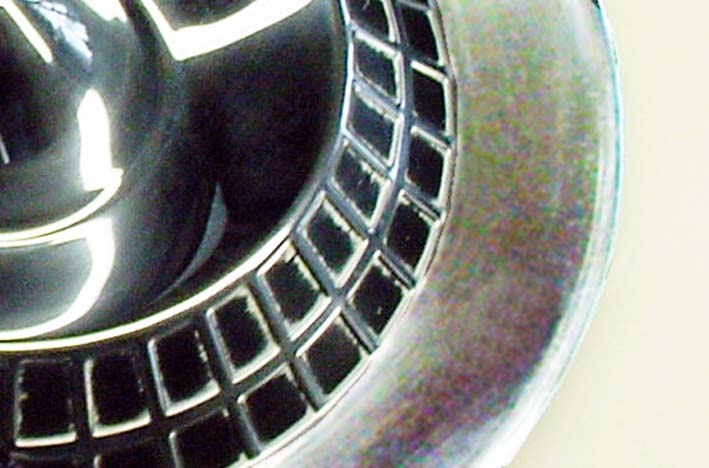 (DSC00058L Old Outworn Paint.jpg) (DSC00058L Old Outworn Paint.jpg)
 (DSC02977L Stamping Tools.jpg) (DSC02977L Stamping Tools.jpg)
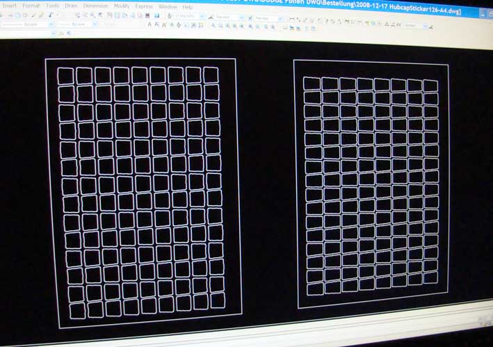 (DSC02970L CAD Design A4.jpg) (DSC02970L CAD Design A4.jpg)
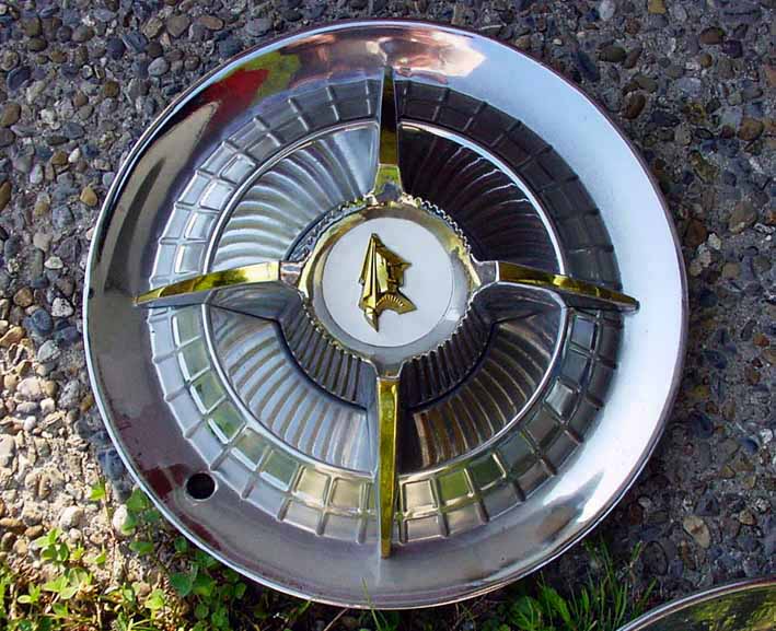 (DSC00025L White Center Sticker.jpg) (DSC00025L White Center Sticker.jpg)
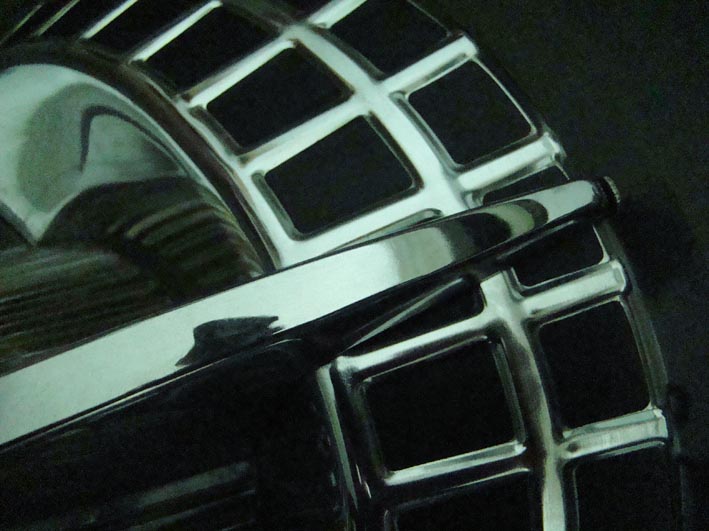 (DSC01930L Black Stickers.jpg) (DSC01930L Black Stickers.jpg)
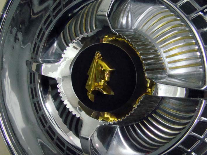 (DSC02972L Black Center Sticker.jpg) (DSC02972L Black Center Sticker.jpg)
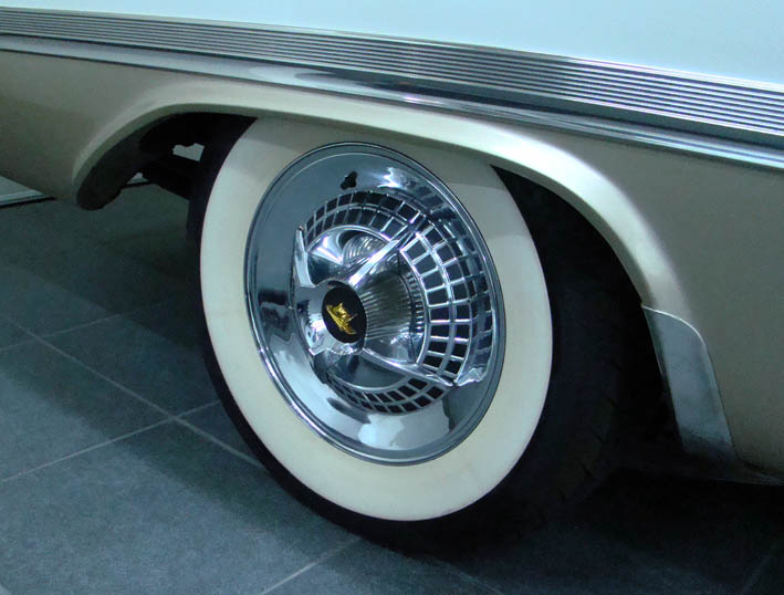 (DSC02975L All Stickers on HubCap.jpg) (DSC02975L All Stickers on HubCap.jpg)
Attachments
----------------
DSC00058L Old Outworn Paint.jpg (65KB - 651 downloads)
DSC02977L Stamping Tools.jpg (58KB - 640 downloads)
DSC02970L CAD Design A4.jpg (84KB - 653 downloads)
DSC00025L White Center Sticker.jpg (103KB - 637 downloads)
DSC01930L Black Stickers.jpg (80KB - 677 downloads)
DSC02972L Black Center Sticker.jpg (90KB - 608 downloads)
DSC02975L All Stickers on HubCap.jpg (76KB - 669 downloads)
|
|
| |
|
Expert
Posts: 1215
Location: SWITZERLAND | Automatic Beam-Changer: This Option was not on my Car when purchased. One day I found solely the Original Sensor Module, and I thought: “Why not?”
I designed a Transistor Trigger Circuit, soldered on a Board and mount under the Dashboard for direct access. A Printed Circuit Board (PCB) would have a quarter of Size. To eliminate the often discussed Flashing in Operate Mode, I set a higher Hysteresis (= Difference between ON – OFF Transition) and a longer ON Time-Constant (10 millisec for Beam OFF, +2 sec for Beam ON), as a manual Switching. The preset of the Sensitivity is done by the Trimmer on the Circuit Board (not visible), directing in the Garage a Pocket Lamp to the Beamer Unit to simulate the Light of an oncoming Car. The fine Adjustment when driving by turning the rear Knob on the Sensor Unit. Now, the Automatic Headlight Control works excellently, but still remains critical in some Light Conditions due to the limited Viewing Angle of the Photo-Cell. Another Optional Equipment, not necessarily needed, but always nice to have. :)
To know: the Automatic Inside Mirror - MirrorMatic uses the same basic circuit, both use the same Vacuum Tube 12k5. A PCB Transistor Circuit would fit in this Housing, or the Tube could simply be substituted by adequate Transistors, directly plug in the Tube Socket (12V Operation).
Edited by sermey 2009-01-29 9:51 AM
 (1 Ross Roy - Automatic Beam-Changer L.jpg) (1 Ross Roy - Automatic Beam-Changer L.jpg)
 (2 DSC03002L Transistor Circuit & Relais.jpg) (2 DSC03002L Transistor Circuit & Relais.jpg)
 (3 DSC02982L Beamer Unit .jpg) (3 DSC02982L Beamer Unit .jpg)
 (4 DSC03000L Beamer OverView.jpg) (4 DSC03000L Beamer OverView.jpg)
Attachments
----------------
1 Ross Roy - Automatic Beam-Changer L.jpg (54KB - 684 downloads)
2 DSC03002L Transistor Circuit & Relais.jpg (89KB - 652 downloads)
3 DSC02982L Beamer Unit .jpg (47KB - 683 downloads)
4 DSC03000L Beamer OverView.jpg (81KB - 696 downloads)
|
|
| |
|
Expert
Posts: 1215
Location: SWITZERLAND | Dimmer Switch: Even when not directly visible, this Switch can easy be upgraded just by putting a Rubber Cap (not Plastic, Bore Dia. 22mm x 20), as used for Chairs. Now, the covered Knob not only looks more discreet and similar to the Windshield Washer Pad, applying the Dimmer Switch feels much more comfortable. Comparing both Pictures it even seems, without the Rubber Cap something is missing. A quite simply improvement for any Oldtimer!
Edited by sermey 2009-01-31 4:39 AM
 (DSC03036L Rubber Cap.jpg) (DSC03036L Rubber Cap.jpg)
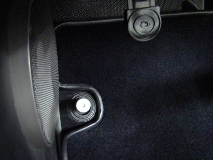 (DSC03051L Original Dimmer Switch.jpg) (DSC03051L Original Dimmer Switch.jpg)
 (DSC03050L Dimmer Switch with Rubber Cap.jpg) (DSC03050L Dimmer Switch with Rubber Cap.jpg)
Attachments
----------------
DSC03036L Rubber Cap.jpg (39KB - 660 downloads)
DSC03051L Original Dimmer Switch.jpg (67KB - 689 downloads)
DSC03050L Dimmer Switch with Rubber Cap.jpg (67KB - 683 downloads)
|
|
| |
|
Expert
Posts: 1215
Location: SWITZERLAND | Sun Visors: On a Convertible the Sun Visors have an additional Function. In slightly higher than in horizontal Position they can reduce the Turbulences at open Top, acting as a virtual Extension of the Windshield. Then they are additionally exposed to a displacement. To tighten a hanging Sun Visor, pull it out (may need some force), put in a parallel vice between two plane planks, protect it as illustrated, then squeeze a little bit in several steps until fixed enough. Now, the Sun Visors remain in any circumstances at the preset Position.
Edited by sermey 2009-01-31 3:04 PM
 (DSC03074L Removed Sun Visor.jpg) (DSC03074L Removed Sun Visor.jpg)
 (DSC03069L Retense The Sun Visor.jpg) (DSC03069L Retense The Sun Visor.jpg)
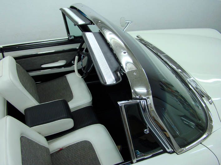 (DSC03068L Sun Visor Up.jpg) (DSC03068L Sun Visor Up.jpg)
Attachments
----------------
DSC03074L Removed Sun Visor.jpg (49KB - 664 downloads)
DSC03069L Retense The Sun Visor.jpg (71KB - 669 downloads)
DSC03068L Sun Visor Up.jpg (78KB - 656 downloads)
|
|
| |
|
Expert
Posts: 1215
Location: SWITZERLAND | 15” Wheels and Tires: I always found, 14” Wheels on my Car are relatively too small and look poor in Proportion to the Body and its Wheelhouse. Must say, this was the Style at this time. The other Point, bigger and wider Tires have much better Adhesion on the Street, the 235/70/15 Radial Tires about +25% in Comparison to the Original 14” Diagonal ones. This improvement is necessarily needed for a full Advantage of Disk Brakes. Thus, I decided in favor of 15” Wheels and the corresponding WWW Tires, still keeping the Original 14” Wheel Set including the Spinner Hubcaps. In order to keep the Original Appearance, the Original HubCaps should fit to the 15” Rims. I bought 15” decorative stainless Rings, cut out the Border around, and soldered it inside the Wheel Cover. For a stronger Fixing on the rechromed Wheels I increased the Clamp Pression by putting a soft round PVC Profile under the Clamps. Now, the Hubcaps fit perfectly to the 15” Rims, their Edges are even protected from Curbstones due to the inner Position, and the Air Valve is perfectly centered as well. According my personal feeling, this Wheel Size gives the Car its settled Proportions. Another improvement of the Outfit, for the Drivers Security, and as an additional Benefit the Wheel Cover Edge Protection. (can see, my HubCaps are not perfect, but polished and with the sticked Black they look as)
Edited by sermey 2009-02-01 12:24 PM
 (Original Wheel and Parking Lamp.jpg) (Original Wheel and Parking Lamp.jpg)
 (1 DSC00001L Coker Tires 235-70-15.jpg) (1 DSC00001L Coker Tires 235-70-15.jpg)
 (2 DSC03078L 15 Inch Decorative Stainless Rings.jpg) (2 DSC03078L 15 Inch Decorative Stainless Rings.jpg)
 (3 DSC00051L Soldered 15 Inch Ring.jpg) (3 DSC00051L Soldered 15 Inch Ring.jpg)
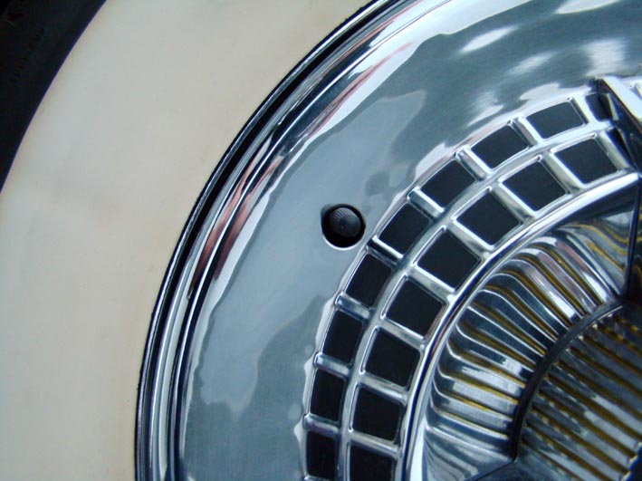 (4 DSC03081L Inner Border of HubCap.jpg) (4 DSC03081L Inner Border of HubCap.jpg)
 (5 DSCN0012L 15 Inch Wheel Assembled.jpg) (5 DSCN0012L 15 Inch Wheel Assembled.jpg)
Attachments
----------------
Original Wheel and Parking Lamp.jpg (73KB - 681 downloads)
1 DSC00001L Coker Tires 235-70-15.jpg (101KB - 672 downloads)
2 DSC03078L 15 Inch Decorative Stainless Rings.jpg (67KB - 655 downloads)
3 DSC00051L Soldered 15 Inch Ring.jpg (68KB - 621 downloads)
4 DSC03081L Inner Border of HubCap.jpg (89KB - 648 downloads)
5 DSCN0012L 15 Inch Wheel Assembled.jpg (97KB - 648 downloads)
|
|
| |
|
Expert
Posts: 1215
Location: SWITZERLAND | obsolete
Edited by sermey 2009-12-04 5:07 PM
|
|
| |
|
Expert
Posts: 1215
Location: SWITZERLAND | Dome Nuts and Caps: These devices remove optically bad nuts, covers them or even protect them. Dome Nuts in polished stainless steel may appear as small diamonds. A low-cost "Jewel+ for your car! - SERGE -  :laugh: :laugh:
 (01 Dome Nuts - Caps DSC03156.jpg) (01 Dome Nuts - Caps DSC03156.jpg)
 (02 DomeCap DSC03154.jpg) (02 DomeCap DSC03154.jpg)
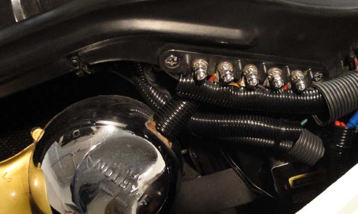 (03 DomeNuts Connector DSC00632a.jpg) (03 DomeNuts Connector DSC00632a.jpg)
 (04 DomeNuts Induction Coil.jpg) (04 DomeNuts Induction Coil.jpg)
Attachments
----------------
01 Dome Nuts - Caps DSC03156.jpg (48KB - 659 downloads)
02 DomeCap DSC03154.jpg (53KB - 663 downloads)
03 DomeNuts Connector DSC00632a.jpg (55KB - 640 downloads)
04 DomeNuts Induction Coil.jpg (79KB - 629 downloads)
|
|
| |
|
Expert
Posts: 1215
Location: SWITZERLAND | Plugged Instruments and Speedometer Units: Working on this Units, what ever the brand of the car, was always a mess for not scratching the painted surrounding, interrupt unintentionally a connection, produce accidentally a short-circuit (when battery unplugged) and even to fix them when working. On newer cars the Units can be removed by unplugging many cables. On our FL-cars, except for the lamps, most cables are fixed.
To avoid these problems, before restoring the gauges, I did these Units pluggable by a multiple pin connector. First I replaced all wires by 50cm long, flexible ones at adequate profile and different colors. When tested I assembled them to a common harness, then cut it and inserted a high current, multiple pin connector. For the most important wires (GND and +12V), delivering the main power, I used two pins in parallel, all pins being soldered. On the Instuments Unit the harness-outlet was set behind the headlamp-switch for an easy turn away to the right side (in the pics folded for re-install the unit).
The remaining connections to remove individually are the speedometer cable, the oil pressure hose and the clock adjustment cable. The ammeter loop, with the cable leading from the one wire alternator to the battery, got a separate interconnection (100A). The thinner black cables leeds to the battery-box (Type 1.5V, UM-6) just deposit under the dashboard for the quartzed clock, working non-stop since already 4 years. On the Speedometer Unit, the brown capton-adhesive tape fixes the fine wires for the four green Micro-LEDs set on the glass end face for an additional impressive illumination of the speed numbers (see Pic above in "Directional Flasher").
Now, a stressfree comfortable handling of the Instruments is possible, beside the dashboard or on a working table! – SERGE - ;) ;)
Edited by sermey 2009-12-06 11:00 AM
 (2009-04-23 DSC03212 Speedometer Unit.jpg) (2009-04-23 DSC03212 Speedometer Unit.jpg)
 (2009-04-23 DSC03206 Front Instruments Panel.jpg) (2009-04-23 DSC03206 Front Instruments Panel.jpg)
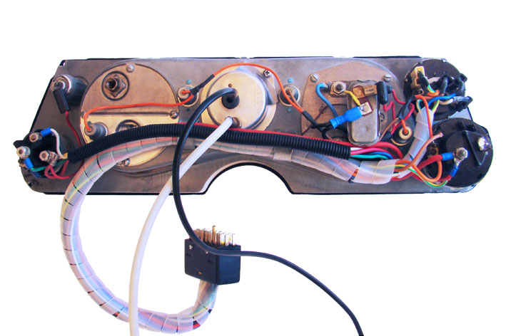 (2009-04-23 DSC03205 Rear Instruments Panel.jpg) (2009-04-23 DSC03205 Rear Instruments Panel.jpg)
 (2009-04-23 DSC03204 View Under Dashboard.jpg) (2009-04-23 DSC03204 View Under Dashboard.jpg)
Attachments
----------------
2009-04-23 DSC03212 Speedometer Unit.jpg (58KB - 611 downloads)
2009-04-23 DSC03206 Front Instruments Panel.jpg (82KB - 626 downloads)
2009-04-23 DSC03205 Rear Instruments Panel.jpg (88KB - 637 downloads)
2009-04-23 DSC03204 View Under Dashboard.jpg (129KB - 643 downloads)
|
|
| |
|
Expert
Posts: 1215
Location: SWITZERLAND | Rechromed Substitute Parts: On the market there are many rechromed parts available as substitutes, additional eye-catchers. Here two samples. The Generator Bracket. Fits directly. For a nicer look can be shortened for best match, as I did here. The Oil DipStick with the Tube. I bent the tube according the position I liked. Then, unfortunately the Oil DipStick couldn't be inserted anymore in the tube. Easy trick: Just twist it! :laugh: - SERGE -
 (Rechromed Generator Braket LL.jpg) (Rechromed Generator Braket LL.jpg)
 (Rechromed Distributor HoldDown LL.jpg) (Rechromed Distributor HoldDown LL.jpg)
 (Rechromed Oil DipStick LL.jpg) (Rechromed Oil DipStick LL.jpg)
 (Rechromed Oil DipStick Twisted LL.jpg) (Rechromed Oil DipStick Twisted LL.jpg)
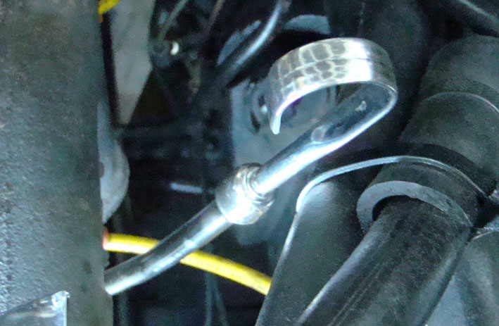 (Rechromed DipStick in Tube LL.jpg) (Rechromed DipStick in Tube LL.jpg)
Attachments
----------------
Rechromed Generator Braket LL.jpg (92KB - 633 downloads)
Rechromed Distributor HoldDown LL.jpg (75KB - 642 downloads)
Rechromed Oil DipStick LL.jpg (64KB - 625 downloads)
Rechromed Oil DipStick Twisted LL.jpg (40KB - 638 downloads)
Rechromed DipStick in Tube LL.jpg (97KB - 610 downloads)
|
|
| |
|
Elite Veteran
Posts: 1107
Location: Arvada, Colorado (NW Denver Metro Area) | Serge, You have a beautiful well detailed car. You should go back in time an be a stylist for Chrysler back in the Forward Look days. Though my 59 Plymouth convert is not at your higher trim level, I will use a lot of the detail points to bring out the best in my instrument panel.
PS I have never seen here in the States Dupli-color in the RAL color system. I am in the electrical business now (20 years )and we use the RAL paint system for coloring large electrical enclosures. I will have to see if they market these RAL colors in the US of A. It would help me a lot in getting touch up paint.
|
|
| |
|
Expert
Posts: 1215
Location: SWITZERLAND | 1959 Belvedere Conv - 2010-02-14 2:49 AM Serge, You have a beautiful well detailed car. You should go back in time an be a stylist for Chrysler back in the Forward Look days. Though my 59 Plymouth convert is not at your higher trim level, I will use a lot of the detail points to bring out the best in my instrument panel. PS I have never seen here in the States Dupli-color in the RAL color system. I am in the electrical business now (20 years )and we use the RAL paint system for coloring large electrical enclosures. I will have to see if they market these RAL colors in the US of A. It would help me a lot in getting touch up paint. Thank you, John. Every one has his own talents. We all have got them for free. The ones uses them more, the others less. I think, most owner of an oldtimer will find and trim his car to a higher level, as soon he has done all needed restorations. Owning just one car is much easier. The RAL Colors are well defined Color Standards and available on a CD, indicating the RGB (Red-Green-Blue) percents, awell known by Photoshop-Users. Thus, any RAL Color can be mixed accordingly, and get exactly the same tone.
Edited by sermey 2010-02-15 10:49 AM
|
|
| |
|
Expert
Posts: 1215
Location: SWITZERLAND | Oil Cap on Valve Cover: This is another part that can be directly replaced by a similar rechromed one, also available on the market.
Here I preferred to keep the Original Cap of the 1959 DODGE with the script "OIL" on top. Bevor rechroming, the steel filter preventing oil to leak on the valve cover, has to be removed. It can be replaced by a rough stainless steel wool, as used for cleaning pans, inserted with a long-nosed plier. A fine steel Wool would clog when oily and prevent the needed air breathing.
Valve Cover: There are as well rechromed valve covers available, What you see are the rechromed originals. To rechrome with polishing costs more than than a replacement. - SERGE -
Edited by sermey 2010-02-15 1:14 PM
 (1959 Original Rechromed Oil Cap LL.jpg) (1959 Original Rechromed Oil Cap LL.jpg)
 (Oil Cap Stainless Steel Wool LL.jpg) (Oil Cap Stainless Steel Wool LL.jpg)
 (361 Oil Cap on Valve Cover LL.jpg) (361 Oil Cap on Valve Cover LL.jpg)
Attachments
----------------
1959 Original Rechromed Oil Cap LL.jpg (55KB - 741 downloads)
Oil Cap Stainless Steel Wool LL.jpg (66KB - 764 downloads)
361 Oil Cap on Valve Cover LL.jpg (126KB - 769 downloads)
|
|
| |
|
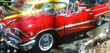
Expert
Posts: 2244
Location: Yorba Linda, Ca | Nice job on the car "Make up". Maybe when you are done, we can switch cars for a while and you can do mine.
Or you could come out here, weather is great today, probably be close to 30C so come here, I give ya free room and board, while you update the makeup on ny car!!!
Gary |
|
| |
|
Expert
Posts: 1215
Location: SWITZERLAND | 1959 Belvedere Conv - 2010-02-14 2:49 AM Serge, You have a beautiful well detailed car. You should go back in time an be a stylist for Chrysler back in the Forward Look days. John, I have done some small stylist modifications, Virgil Exner would even be happy about - but not the purists. 
|
|
| |
|
Expert
Posts: 1215
Location: SWITZERLAND | 1959Dodge - 2010-02-15 7:22 PM Nice job on the car "Make up". Maybe when you are done . . . Sorry, Gary, it is never done. The show goes on! A never ending process. - SERGE -
|
|
| |
|
Board Moderator & Exner Expert 10K+
Posts: 13062
Location: Southern Sweden - Sturkö island | sermey - 2010-02-15 4:39 PM
Here I preferred to keep the Original Cap of the 1959 DODGE with the script "OIL" on top. Bevor rechroming, the steel filter preventing oil to leak on the valve cover, has to be removed. It can be replaced by a rough stainless steel wool, as used for cleaning pans, inserted with a long-nosed plier. A fine steel Wool would clog when oily and prevent the needed air breathing. - SERGE -
I used exactly the same material and method with Oil Cap - mine is painted black though. |
|
| |
|
Expert
Posts: 2598
Location: Upplands Väsby, Sweden | wizard - 2010-02-17 12:00 PM
sermey - 2010-02-15 4:39 PM
Here I preferred to keep the Original Cap of the 1959 DODGE with the script "OIL" on top. Bevor rechroming, the steel filter preventing oil to leak on the valve cover, has to be removed. It can be replaced by a rough stainless steel wool, as used for cleaning pans, inserted with a long-nosed plier. A fine steel Wool would clog when oily and prevent the needed air breathing. - SERGE -
I used exactly the same material and method with Oil Cap - mine is painted black though.
OK! thanks for this tips: It can be replaced by a rough stainless steel wool, as used for cleaning pans, inserted with a long-nosed plier
I must changes the stainless steel wool in my oil cap. |
|
| |
|
Expert
Posts: 1215
Location: SWITZERLAND | Constant Voltage Regulator: This is a thermo-mechanical contact breaker, and cannot be repaired (metallic sealed). It's output is a pulsing 12V, resulting in an average output of 5Volt. This voltage can only be measured with a long-time integrating instrument. A connected 12V instruments bulb will flash correspondingly. The regulator is used to operate both, the fuel level and the temperature gauges.
I found an electronic device for direct replacement and easy mounting. It doesn't need any additional components, produces a constant Voltage of +5.0V within an input range of 9 - 30 Volts. This device is temperature and short circuit protected, therefore cannot be destroyed. Just move the input and output connection of the breaker to the input / output of the electronic device. The output leads to the fuel level and temperature gauges. The ground (-) is already connected by the fixing screw of the original regulator (heat sink!). Thus the center pad (ground) could be cut. The maximum output current of 1.5A is more than double needed by the fuel level and temperature gauges at full readings. The readings for two Input Voltages of 9 and 18 Volt, and the water temperature gauge loaded for "normal" reading (sensor simulation R = 22 Ohm, see Pic) have been tested. The output of the device shows a constant value of 4.90 Volt. The original voltage regulator can be left there as is, but unconnected, or it can be removed as shown. On the illustrations the device is not connected (demo on a spare instruments panel), best should be soldered. Another invisible new technology for a better performance and a higher reliability of your car. - SERGE - :laugh: To know: I have purchased some additional devices for interested FWLs and can offer them at cost price: USD 5.00/piece plus shipment by letter (PAYPAL sermey@bluewin.ch).
Edited by sermey 2010-02-24 1:48 PM
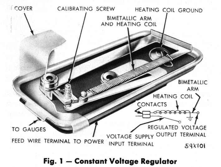 (1 - Dodge59 Constant Voltage Regulator LL.jpg) (1 - Dodge59 Constant Voltage Regulator LL.jpg)
 (2 - Electronic Regulator Pin Connection LL.jpg) (2 - Electronic Regulator Pin Connection LL.jpg)
 (3 - Reading at 9 Volt Input LL.jpg) (3 - Reading at 9 Volt Input LL.jpg)
 (4 - Reading at 18 Volt Input LL.jpg) (4 - Reading at 18 Volt Input LL.jpg)
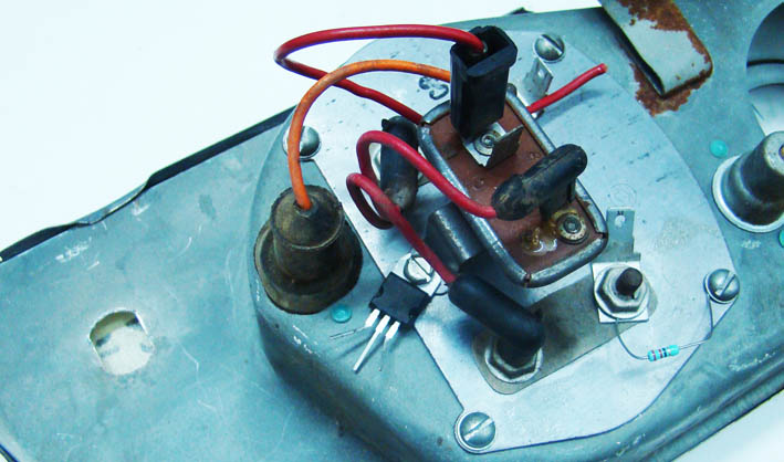 (5- Both 5 Volt Regulators Mounted LL.jpg) (5- Both 5 Volt Regulators Mounted LL.jpg)
 (6 - Only Electronic 5 Volt Regulator Mounted LL.jpg) (6 - Only Electronic 5 Volt Regulator Mounted LL.jpg)
Attachments
----------------
1 - Dodge59 Constant Voltage Regulator LL.jpg (92KB - 658 downloads)
2 - Electronic Regulator Pin Connection LL.jpg (64KB - 702 downloads)
3 - Reading at 9 Volt Input LL.jpg (81KB - 694 downloads)
4 - Reading at 18 Volt Input LL.jpg (90KB - 732 downloads)
5- Both 5 Volt Regulators Mounted LL.jpg (80KB - 667 downloads)
6 - Only Electronic 5 Volt Regulator Mounted LL.jpg (93KB - 677 downloads)
|
|
| |
|
Expert
Posts: 1215
Location: SWITZERLAND | Remote Hood Lock: Most cars at this era didn't had this option. Everyone could open the hood from front, the ones for curiousity, the others just for steal the battery as experienced many years ago. Thus, I had not a good feeling with an "open" hood on my Dodge.
I found a "HOOD" remote cable (must be from a 1960 Mopar?), purchased later a NOS hood lock on eBay, and now it is mounted. The hood lock arm had to be cut and bent upward for a functional operation, and for preventing from manual open. Then the end of the arm got a thread (M5) with a groove for easy connecting and the fine adjustment of the cable length. The remote hood lock handle is mounted on the drivers left side, under the dashboard.
Now, the battery (and the oval air filters!) are safe, and not anymore opened hood by curious people. - SERGE -
Edited by sermey 2010-02-25 4:28 PM
 (1 - Hood Lock - Arm Cut LL.jpg) (1 - Hood Lock - Arm Cut LL.jpg)
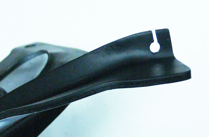 (2 - Prepared Lock Arm LL.jpg) (2 - Prepared Lock Arm LL.jpg)
 (3 - Remote Cabel End LL.jpg) (3 - Remote Cabel End LL.jpg)
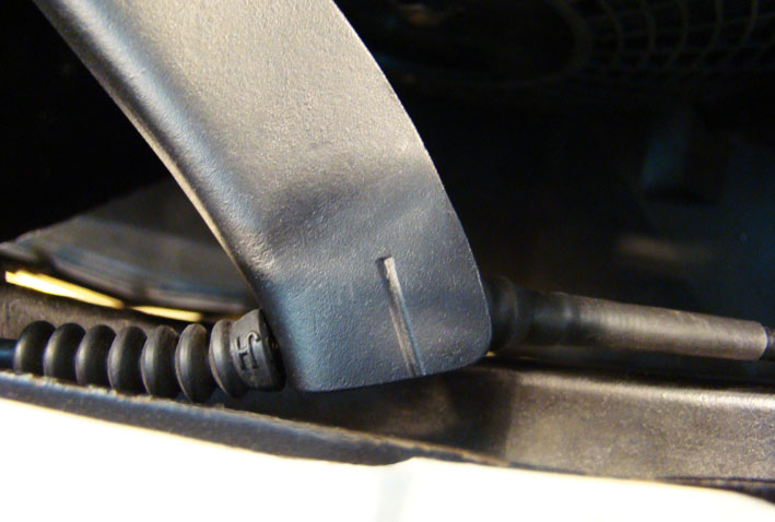 (4 - Control Cabel Connection LL.jpg) (4 - Control Cabel Connection LL.jpg)
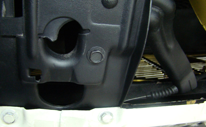 (5 - Connected Remote Control LL.jpg) (5 - Connected Remote Control LL.jpg)
 (6 - Remote Hood Lock Handle LL.jpg) (6 - Remote Hood Lock Handle LL.jpg)
Attachments
----------------
1 - Hood Lock - Arm Cut LL.jpg (60KB - 696 downloads)
2 - Prepared Lock Arm LL.jpg (59KB - 686 downloads)
3 - Remote Cabel End LL.jpg (43KB - 684 downloads)
4 - Control Cabel Connection LL.jpg (75KB - 707 downloads)
5 - Connected Remote Control LL.jpg (85KB - 699 downloads)
6 - Remote Hood Lock Handle LL.jpg (75KB - 707 downloads)
|
|
| |
|

Board Moderator
Posts: 3186
Location: The not-so-great, dirty-white North ( Michigan) | sermey - 2010-02-24 11:07 AM
Constant Voltage Regulator: This is a thermo-mechanical contact breaker, and cannot be repaired (metallic sealed). It's output is a pulsing 12V, resulting in an average output of 5Volt. This voltage can only be measured with a long-time integrating instrument. A connected 12V instruments bulb will flash correspondingly. The regulator is used to operate both, the fuel level and the temperature gauges.
I found an electronic device for direct replacement and easy mounting. It doesn't need any additional components, produces a constant Voltage of +5.0V within an input range of 9 - 30 Volts. This device is temperature and short circuit protected, therefore cannot be destroyed. Just move the input and output connection of the breaker to the input / output of the electronic device. The output leads to the fuel level and temperature gauges. The ground (-) is already connected by the fixing screw of the original regulator (heat sink!). Thus the center pad (ground) could be cut. The maximum output current of 1.5A is more than double needed by the fuel level and temperature gauges at full readings. The readings for two Input Voltages of 9 and 18 Volt, and the water temperature gauge loaded for "normal" reading (sensor simulation R = 22 Ohm, see Pic) have been tested. The output of the device shows a constant value of 4.90 Volt. The original voltage regulator can be left there as is, but unconnected, or it can be removed as shown. On the illustrations the device is not connected (demo on a spare instruments panel), best should be soldered. Another invisible new technology for a better performance and a higher reliability of your car. - SERGE - :laugh: To know: I have purchased some additional devices for interested FWLs and can offer them at cost price: USD 5.00/piece plus shipment by letter (PAYPAL sermey@bluewin.ch).
Serge.....
If you really want to make it look "original", you can mount the 5V regulator on a PC board inside the old regulator housing.
That is what I have done with the Lucas equivalent on my Lotus Europa........
|
|
| |
|
Expert
Posts: 1215
Location: SWITZERLAND | DeSotohead: ..... If you really want to make it look "original", you can mount the 5V regulator on a PC board inside the old regulator housing. This is a good idea, Hank. Then the integrated circuit can directly be soldered inside on the existing pins. It will need a screw for the heat sink, and on the Dodge, the metallic housing of the regulator is bent all around and must be opened (?). I don't know if the other Mopars use the same regulator.
Edited by sermey 2010-02-25 10:31 AM
|
|
| |
|
Board Moderator
Posts: 3186
Location: The not-so-great, dirty-white North ( Michigan) | Here is how its done for the Europas.....
 (5vregulator.gif) (5vregulator.gif)
Attachments
----------------
5vregulator.gif (57KB - 687 downloads)
|
|
| |
|
Expert
Posts: 1215
Location: SWITZERLAND | This is the same Mopar Regulator. But this one has only two bent edges. The one in my car (see above Pic 5) is bent all around. The electronic regulator is a similar one, may-be an earlier product. There are many available, from various manufacturers and for different applications. The one I selected is best for our application and, according the datasheet, doesn't need any components at all (internally compensated), and cannot be destroyed (temperature and current protected). This security is a big advantage, thinking the regulator is located behind the instruments panel and not directly accessible. Not needed, but the output accuracy in respect to the input range as tested is impressive (4.90V). Too precise for cars of the fifties!
Edited by sermey 2010-02-25 11:18 AM
|
|
| |
|
Board Moderator
Posts: 3186
Location: The not-so-great, dirty-white North ( Michigan) | THe actual 5V regulator is really not an issue. As you point out, several companies make them, including the infamous adjustible "LM317" regulator from National.
As for your housing, I think it is quite possible to bend the four corners up and away.
You might try heating the metal with a small butane torch as you pry, or use a large tip on a soldering iron.
Once removed, you can finish the bent up taba with a small hammer and a piece of steel as a backer to straighten the metal.
Recrimping can be done with a small anvil vise. |
|
| |
|
Expert
Posts: 1215
Location: SWITZERLAND | Fixing the Spinner Hubcaps: I guess these 1959 hubcaps may be the heaviest ones among the FWL- cars. As the spinners are just mounted on the wheel covers and remain unbalanced, an asymmetric radial force is being applied on the rims when driving. The pression to the rims is increased on the one side, and reduced correspondingly on the opposite side. This causes the spinner hubcaps to move slightly outwards on the reduced force side. Mechanical shocks on bad streets to the critical diameter accelerates this process. The front wheels, especially the right side one (for right. hand traffic), are more exposed then the rear ones. I have observed on some hubcaps an outward displacement up to 1mm after a trip of about 500km. Therefore the fit of the hubcaps have to be checked at regular intervals.
Once it happens me to loose the front right spinner hubcap on the original rims. Fortunately I noticed this on the spot and could retrieve it. After that, on longer trips to car meetings, I safety removed the hubcaps. This caused to miss a winner "best of show", forgetting to put on the hubcaps, laying behind the front seats. Not only, but for best presentation this car needs the original hubcaps. It even happened by an oversight to take pictures without hubcaps. Now I had to find a solution!
Diametral in the 15" chrome-wheels I removed two diametric nuts (the nuts are just dummies as design) and put an M5 inserting-nut instead (as described earlier). The position has to match the air-valve! Then I bent a profile in aluminium as fixing latch, with an M4 inserting-nut (here in aluminium black anodized) on one end. For each hubcap two latches are needed. The fine adjustment to the hubcaps is done by rotating and manually bending them on the wheel. The hubcaps need two holes (4 mm) in the groove, not drilled, just by applying multiple times the center puncher in order to keep the border for the countersink screws M4. This two stainless screws are hardly visible, on the picture time position 04.50. I still have some reserve wheel covers for keeping the originality, if one day it should be required.
Now, my 1959 Dodge Convertible will always be fitted with the nice spinner hubcaps, without any stress of loosing them or even being "removed" (get stolen). - SERGE -
Edited by sermey 2010-02-27 12:50 PM
 (1 - Inserted Nut LL.jpg) (1 - Inserted Nut LL.jpg)
 (2 - Fixing Latches LL.jpg) (2 - Fixing Latches LL.jpg)
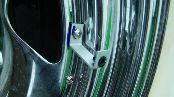 (3 - Latch Mount LL.jpg) (3 - Latch Mount LL.jpg)
 (4 - Mounted Latches LL.jpg) (4 - Mounted Latches LL.jpg)
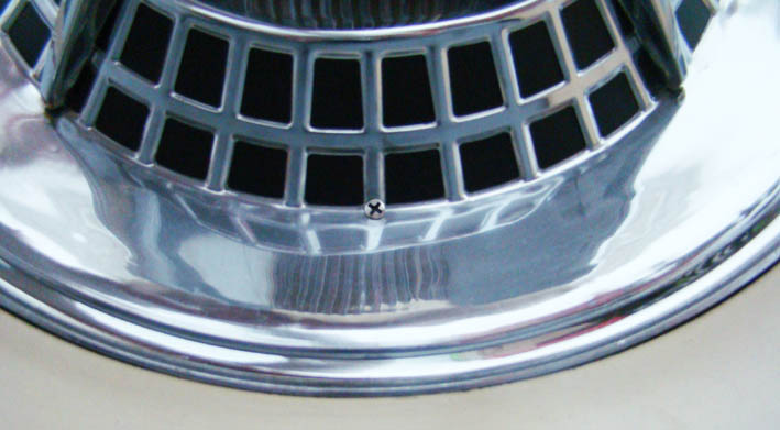 (5 - Countersink Screw LL.jpg) (5 - Countersink Screw LL.jpg)
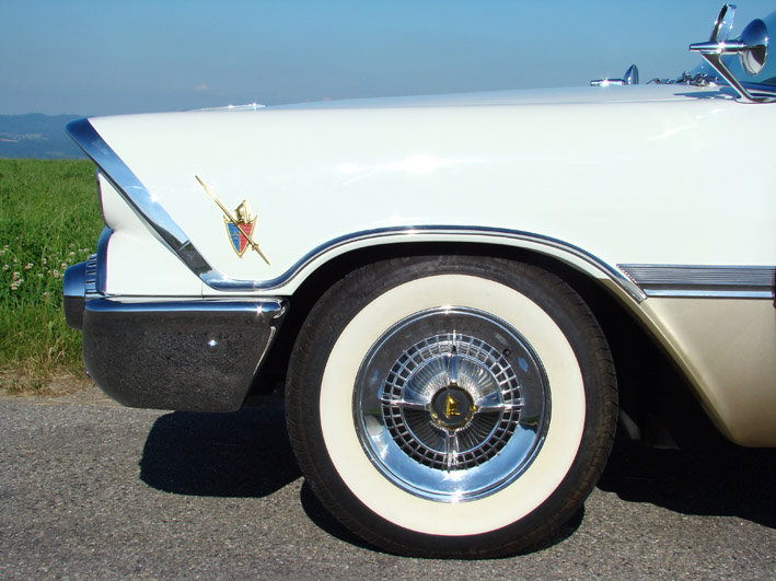 (6 - Fixed Spinner Hubcap LL.jpg) (6 - Fixed Spinner Hubcap LL.jpg)
Attachments
----------------
1 - Inserted Nut LL.jpg (90KB - 643 downloads)
2 - Fixing Latches LL.jpg (65KB - 663 downloads)
3 - Latch Mount LL.jpg (73KB - 695 downloads)
4 - Mounted Latches LL.jpg (109KB - 678 downloads)
5 - Countersink Screw LL.jpg (65KB - 695 downloads)
6 - Fixed Spinner Hubcap LL.jpg (124KB - 665 downloads)
|
|
| |
|
Expert
Posts: 1215
Location: SWITZERLAND | Fuel Gas Tank Cap: On most FWL-Cars the Fuel Gas Tank Cap is not visible from outside, on many Sports Cars it is part of the design and lettered accordingly (GT, SS). On a nice car, this device should as well correspond to the car, to its design and to the prefences of the owner. On the market there are various caps available, with and without locks. The pictures show a selection offered in eBay. For my car the Fuel Gas Tank Cap should have the properties as:
1. Vented type, preventing pressions in the tank.
2. With lock, protecting the acces to others.
3. Covered lock, to keep it free from dirt.
4. The ability to fix it without key.
5. A nice rechromed design, matched to the car.
Now, when tank up, the nice Fuel Gas Tank Cap underscores the exclusivity of the car. - SERGE -
Edited by sermey 2010-03-22 6:38 AM
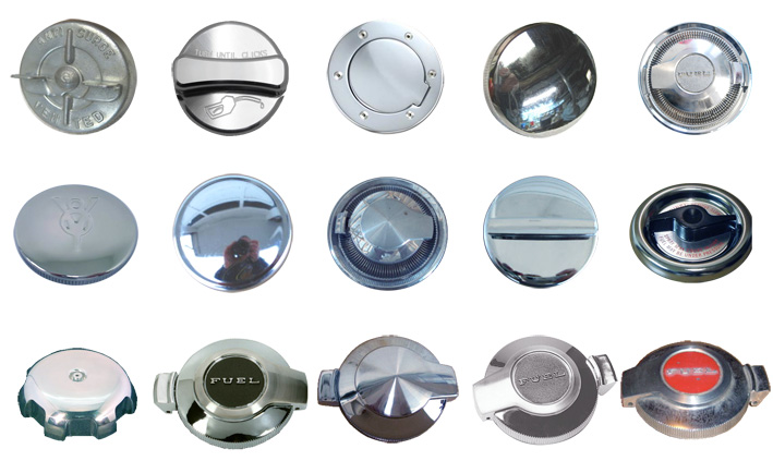 (1 - Various Gas Tank Caps LL.jpg) (1 - Various Gas Tank Caps LL.jpg)
 (2 - Various Locking Gas Tank Cap LL.jpg) (2 - Various Locking Gas Tank Cap LL.jpg)
 (3 - Dodge Fuel Gas Tank Cap LL.jpg) (3 - Dodge Fuel Gas Tank Cap LL.jpg)
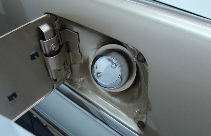 (4 - Dodge Fuel Cap Fixed LL.jpg) (4 - Dodge Fuel Cap Fixed LL.jpg)
 (5 - Dodge Fuel Cap with Keys LL.jpg) (5 - Dodge Fuel Cap with Keys LL.jpg)
Attachments
----------------
1 - Various Gas Tank Caps LL.jpg (115KB - 660 downloads)
2 - Various Locking Gas Tank Cap LL.jpg (99KB - 644 downloads)
3 - Dodge Fuel Gas Tank Cap LL.jpg (53KB - 695 downloads)
4 - Dodge Fuel Cap Fixed LL.jpg (53KB - 673 downloads)
5 - Dodge Fuel Cap with Keys LL.jpg (83KB - 651 downloads)
|
|
| |
|
Expert
Posts: 1215
Location: SWITZERLAND | Trunk Lamp: Older cars have usually one trunk lamp, positioned in the center of the trunk, near the lock. The switch is in the bulb socket, activated at a given angle or inclination. For a big trunk like on FWL-cars, this illumination can be insufficient at the left and right end, especially when the trunk is dark carpeted. Additional lamps could be useful.
I found Lamp Units with integrated switch, for individually On or Off. As separate switch, the same system is used as in the doors for the dome lamps. This switch is mounted by a bracket behind the trunk hinge (left side) the way, that at closed trunk the lamps goes off. Two lamp units are fixed, left and right, not visible on top in the upper corner. The needed electrical supply is already there.
Another discreet adds-on. At night the opened trunk appear wider and more generous, as the car already is. - SERGE -
Edited by sermey 2010-03-26 6:35 PM
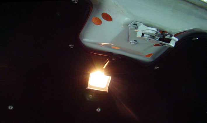 (1 - Trunk Light LL.jpg) (1 - Trunk Light LL.jpg)
 (2 - Trunk Lamp Units LL.jpg) (2 - Trunk Lamp Units LL.jpg)
 (3 - Trunk Light Switch LL.jpg) (3 - Trunk Light Switch LL.jpg)
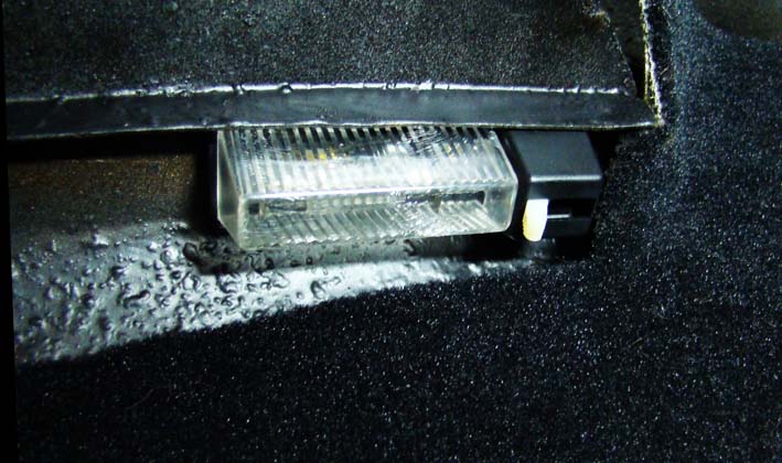 (4 - Mounted Lamp Unit LL.jpg) (4 - Mounted Lamp Unit LL.jpg)
 (5 - Trunk Lamp Unit Left Side View LL.jpg) (5 - Trunk Lamp Unit Left Side View LL.jpg)
Attachments
----------------
1 - Trunk Light LL.jpg (51KB - 684 downloads)
2 - Trunk Lamp Units LL.jpg (65KB - 646 downloads)
3 - Trunk Light Switch LL.jpg (67KB - 683 downloads)
4 - Mounted Lamp Unit LL.jpg (80KB - 672 downloads)
5 - Trunk Lamp Unit Left Side View LL.jpg (81KB - 669 downloads)
|
|
| |
|
Elite Veteran
Posts: 1107
Location: Arvada, Colorado (NW Denver Metro Area) | Serge, in picure 6 of the constant voltage regulator thread, there is a small blue electronic device with stripes used, is that a diode or capacitor you installed? and why?
thanks! |
|
| |
|
Expert
Posts: 1215
Location: SWITZERLAND | 1959 Belvedere Conv - 2010-03-27 1:45 AM Serge, in picure 6 of the constant voltage regulator thread, there is a small blue electronic device with stripes used, is that a diode or capacitor you installed? and why? thanks! John, this is the 22 Ohm resistor (0.3W), simulating the missing temperature sensor. With this value, corresponding to the warm-up engine, the temp gauge shows 60% reading, visible from the other side.This voltage regulator requires no additional electronic device at all. What you see is the rear of a "reserve" instruments panel 1959 Dodge. - SERGE -
Edited by sermey 2010-03-27 2:40 AM
|
|
| |
|
Expert
Posts: 1215
Location: SWITZERLAND | Water Temperature Gauge Sender: Technical aspects about this device have already been discussed on another thread:
"Defective Water Temperature Sensor"
http://www.forwardlook.net/forums/forums/thread-view.asp?tid=29524&posts=15&start=1
Here just a small "Make-up": The pin has been modified by applying a thread M3. This allows a nicer and as well a better electrical connection. Then the device and the dome cap (M3) have been polished. Under the Sensor you see a rubber O-ring to hide its remaining thread.
Now, one more "brillant" on this car! - SERGE -
To know: Polished brass should be protected by coating with Zapon-Laquer to prevent oxydations and to keep the shiny aspect. This is advantageous for any polished metallic items. On pictures the polished surfaces often doesn't look as shiny, due to mirroring of the ambient.
Edited by sermey 2010-03-28 6:29 AM
 (1 - Temperature Gauge Sender LL.jpg) (1 - Temperature Gauge Sender LL.jpg)
 (2 - Thread M3 on Sensor LL.jpg) (2 - Thread M3 on Sensor LL.jpg)
 (3 - Dome Cap M3 on Connected Sensor LL.jpg) (3 - Dome Cap M3 on Connected Sensor LL.jpg)
Attachments
----------------
1 - Temperature Gauge Sender LL.jpg (51KB - 658 downloads)
2 - Thread M3 on Sensor LL.jpg (102KB - 651 downloads)
3 - Dome Cap M3 on Connected Sensor LL.jpg (101KB - 656 downloads)
|
|
| |
|
Expert
Posts: 1215
Location: SWITZERLAND | Black Painted Items: Many items on my car are black painted. Not the style of anyone, but to me for practcal reasons. When clean, it looks nice, can be partly repainted anytime without perceiving it, is neutral and gives a classic outfit. Finally: black is black, no problems with various tones as a white color. This is my personal view.
Here how I do it, easy and nice:
First brush the surface to remove old paint or rust. Then clean it with nitro-dilution or fuel, using a towel or washing the item with a paint-brush, to be absolute free of oil. The best paint I found and use for years is a spray, mat and includes rust-protection. It has a structure as silver paint and dries within a half hour. When the items are not directly exposed to water or rain, this paint can be applied directly on iron (or other material). For hot engine parts there is the similar "high temperature" spray. Inside the car or in corners, the surrounding can be masked with newspapers or a plastic foil, the hidden corners coloured with a paint-brush, using this paint previously sprayed in a can.
As sample I used a rusty metal bar, here (highly zoomed) only brushed, not grinded or sanded. On the last picture, the black painted front of the engine (over 10 years old). The black paint is slightly shiny as silk, what gives an animated look. - SERGE -
See as well the brushed and black painted Hood-Lock in an upper post.
Edited by sermey 2010-04-03 11:20 AM
 (1 - Black Spray LL.jpg) (1 - Black Spray LL.jpg)
 (2 - Rusty Metal LL.jpg) (2 - Rusty Metal LL.jpg)
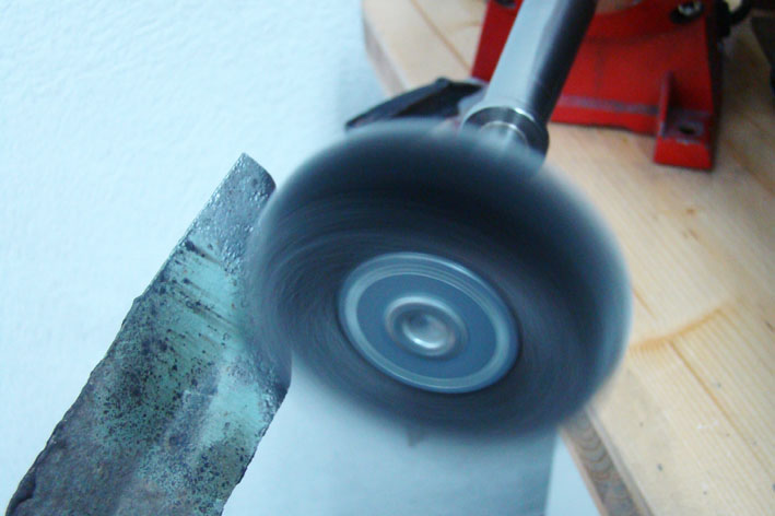 (3 - Brushing LL.jpg) (3 - Brushing LL.jpg)
 (4 - Metal Black Sprayed LL.jpg) (4 - Metal Black Sprayed LL.jpg)
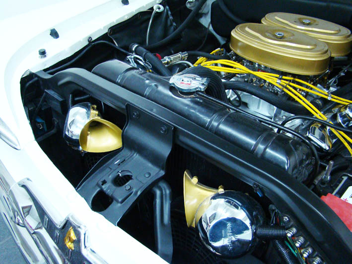 (5 - Black Paint on Front LL.jpg) (5 - Black Paint on Front LL.jpg)
Attachments
----------------
1 - Black Spray LL.jpg (100KB - 684 downloads)
2 - Rusty Metal LL.jpg (68KB - 695 downloads)
3 - Brushing LL.jpg (69KB - 686 downloads)
4 - Metal Black Sprayed LL.jpg (69KB - 684 downloads)
5 - Black Paint on Front LL.jpg (115KB - 672 downloads)
|
|
| |
|
Expert
Posts: 1215
Location: SWITZERLAND | Aligning the Front Bumper: We all know, the precision on those cars was not high as on cars of today. This becomes apparent on mounted doors, hoods and trunk lids, but as well on bumpers. The front bumper of the 1959 Dodge is especially critical due to its side design - any mis-alignment to the fender is visible. When mounted as it is from original, most are hanging down. Some nice cars as illustrated (1) (pics from thread Vasteras) look as the front bumper will get lost at any instance. This was as well on my car.
Correcting this by an asymmetric support would move the bumper more forward. But the bumper should even be more back to fit as well to the border of the fender. To move it more back, the mounting arms have to be shortened. Due to an angle of about 45deg the arms have in respect to the bumper, the mounting holes would not fit anymore by just cutting them. They have to be welded overlapped as shown (2). The adjustment in forward position then is easy achieved by inserting washers (3). The hanging side to come up can be corrected by grinding the bracket correspondingly.
Recently I improved this alignment by slightly untight the bolts, pushing the bumper on the side up to maximum, using the car lifter. Then fixing (just hanging) the bumper up, with two adjustable aluminium angle brackets (3) on each side (4). When aligned and fixed in the correct position, finally tighten all bumper bolts (on Pic 4 you see as well how the Lancer Emblem is fixed, this way already posted earlier).
Now, the front bumper is there where it should be, as it was initially designed. - SERGE -
Edited by sermey 2010-04-24 1:08 PM
 (1 - Hanging Front Bumpers LL.jpg) (1 - Hanging Front Bumpers LL.jpg)
 (2 - Bumper Arm Welding LL.jpg) (2 - Bumper Arm Welding LL.jpg)
 (3 - Forward Adjustment LL.jpg) (3 - Forward Adjustment LL.jpg)
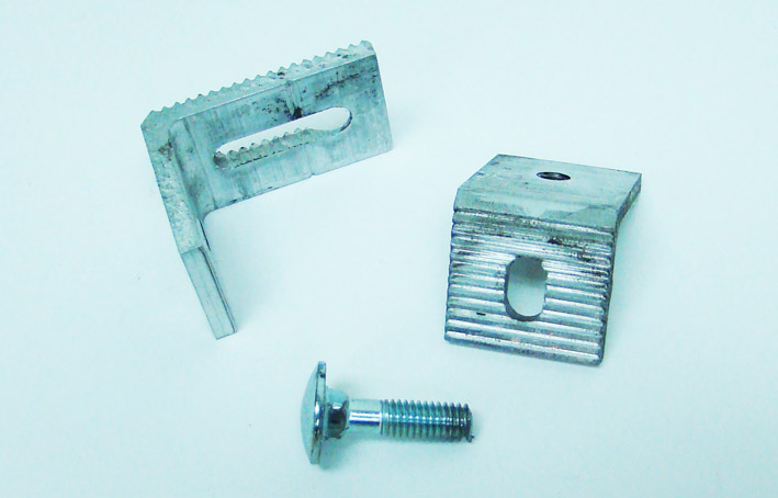 (4 - Adjustable Angle Brackets LL.jpg) (4 - Adjustable Angle Brackets LL.jpg)
 (5 - Front Bumper Fixed in Top Position LL.jpg) (5 - Front Bumper Fixed in Top Position LL.jpg)
 (6 - Aligned Front Bumper LL.jpg) (6 - Aligned Front Bumper LL.jpg)
Attachments
----------------
1 - Hanging Front Bumpers LL.jpg (116KB - 672 downloads)
2 - Bumper Arm Welding LL.jpg (72KB - 690 downloads)
3 - Forward Adjustment LL.jpg (70KB - 663 downloads)
4 - Adjustable Angle Brackets LL.jpg (68KB - 712 downloads)
5 - Front Bumper Fixed in Top Position LL.jpg (86KB - 685 downloads)
6 - Aligned Front Bumper LL.jpg (76KB - 680 downloads)
|
|
| |
|
Board Moderator & Exner Expert 10K+
Posts: 13062
Location: Southern Sweden - Sturkö island | Way to go Serge! You have cured the "American Car disese"! Next to all US cars (exeption from the master renovated ones) has a misaligned bumper. This is indeed a very noticable difference. |
|
| |
|

Expert
Posts: 2679
| I see you have a 22 ohm resistor hooked up there, (red, red, blk) I bet for testing purposes, very good. I replaced my old CVR with a 5 volt 7805 today and a NOS gauge. I let the car idle for 30 minutes and the gauge reads 1/3rd, not bad at all. Tomorrow I will take her out for a ride and see where the gauge reads. Too much rain today. Thanks Sermey for the research and pics. |
|
| |
|
Expert
Posts: 1215
Location: SWITZERLAND | 59CRL - 2010-05-02 1:25 AM I see you have a 22 ohm resistor hooked up there, (red, red, blk) I bet for testing purposes, very good. I replaced my old CVR with a 5 volt 7805 today and a NOS gauge. I let the car idle for 30 minutes and the gauge reads 1/3rd, not bad at all. Tomorrow I will take her out for a ride and see where the gauge reads. Too much rain today. Thanks Sermey for the research and pics. Correct, the 22Ohm Resistor substitutes the sensor. This was technically discussed in the thread: " http://www.forwardlook.net/forums/forums/thread-view.asp?tid=29524&posts=22&start=1 |
|
| |
|
Expert
Posts: 2679
| sermey - 2010-05-01 7:52 PM
59CRL - 2010-05-02 1:25 AM I see you have a 22 ohm resistor hooked up there, (red, red, blk) I bet for testing purposes, very good. I replaced my old CVR with a 5 volt 7805 today and a NOS gauge. I let the car idle for 30 minutes and the gauge reads 1/3rd, not bad at all. Tomorrow I will take her out for a ride and see where the gauge reads. Too much rain today. Thanks Sermey for the research and pics. Correct, the 22Ohm Resistor substitutes the sensor. This was technically discussed in the thread: " http://www.forwardlook.net/forums/forums/thread-view.asp?tid=29524&posts=22&start=1
Bringing this thread back for an update. Sitting at idle with my 7805 voltage regulator I get 1/3rd on the temp gauge. Driving down the highway at
temperatures of 95-100 degrees the gauge will read the same. Sitting in 100 degree heat with the engine idling the gauge will creep upto 3/4.
Not bad at all. |
|
| |
|
Expert
Posts: 1215
Location: SWITZERLAND | Emergency Car Cover: Imagine, you are on the road with your Convertible. It starts raining. You attempt to put up your top. But unfortunately it won't. May-be due to electrical problems, a defective pump, or it just clamps.
In order to prevent your precious interior and the dash instruments to go wet, cover the car around all the interior with a multiple purposes Polyethylen-Foil (min. 0.1mm, 0.004"), and wait still raining has stopped. As illustrated, this cover (5 x 4 m) needs practically no space in the trunk (Package 30 x 38cm), and is always and instantly ready to use. ;) - SERGE -
Edited by sermey 2011-01-16 4:10 AM
 (Emergency Car Cover.jpg) (Emergency Car Cover.jpg)
Attachments
----------------
Emergency Car Cover.jpg (77KB - 652 downloads)
|
|
| |
|
Expert
Posts: 1215
Location: SWITZERLAND | Bullets for Rear View Mirror: A time ago some bullets have been offered in eBay. Even not an original mopar accessory, they went for up nearly USD100 a pair.
With these bullets the mirror looks rather to be complete. Now I found "Chrome Bullet Heads" used as Tire Valve Caps in eBay, a set of 4pcs for USD 8.99, 5/8"x1 1/4" in metal. Proceedings: 1. Insert a cylindrical plastic plug inside the Bullet (D:7.2mm L 12mm), put-in a long screw (M4) till end, this will be tight and used for fixing. Reduce the bullet in length (from 30.5mm to 23.2mm) to fit the mirrors end diameter; cut the screw for remaining 5mm. The Bullet is ready for mount. 2. Remove the mirror nut, drill an M4 thread through, put back the Nut - the mirror is ready for the bullet. Now, just screw-in the assembled bullet, and your Rear View Mirror now shows the visible face lifting. The mirror bullets can easy be removed simply by manually unscrewing, to return to the mirrors standard view. Another gadget for your FWL Car - if you like it. - SERGE -
Edited by sermey 2011-03-09 8:36 AM
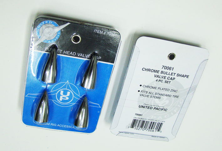 (DSC04478 Set of Tire Valve Caps LL.jpg) (DSC04478 Set of Tire Valve Caps LL.jpg)
 (DSC04477 Plastic Plug and M4 in Mirror Nut LL.jpg) (DSC04477 Plastic Plug and M4 in Mirror Nut LL.jpg)
 (DSC04475 Screw-in the Bullet LL.jpg) (DSC04475 Screw-in the Bullet LL.jpg)
 (DSC04474 Face Lifted Rear View Mirror LL.jpg) (DSC04474 Face Lifted Rear View Mirror LL.jpg)
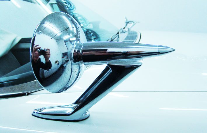 (DSC04473 New Mirror with CameraMan LL.jpg) (DSC04473 New Mirror with CameraMan LL.jpg)
Attachments
----------------
DSC04478 Set of Tire Valve Caps LL.jpg (85KB - 705 downloads)
DSC04477 Plastic Plug and M4 in Mirror Nut LL.jpg (47KB - 785 downloads)
DSC04475 Screw-in the Bullet LL.jpg (56KB - 740 downloads)
DSC04474 Face Lifted Rear View Mirror LL.jpg (58KB - 738 downloads)
DSC04473 New Mirror with CameraMan LL.jpg (77KB - 696 downloads)
|
|
| |
|
Expert
Posts: 1215
Location: SWITZERLAND | Door Panel Protection: When assembling the door panel I had to find a way, for not wear the new coating material at the opening of the door handle, when manipulating with. I took the body of a "Solder Sucking Wick" as used in electronics. This fits exactly in inner and outer diameter, in thickness of the door panel, and as well to the diameter of the handle, as it was designed for this application. Mounted, it doesn't turn at all and doesn't need additional spacers. Now, no friction at all to the padded coating material when manipulating the door handle - an easy and efficient solution - SERGE -
Edited by sermey 2011-03-20 8:15 AM
 (DSC04514 Panel Protector LL.jpg) (DSC04514 Panel Protector LL.jpg)
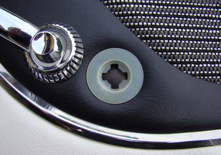 (DSC04515 Panel Protector Mounted LL.jpg) (DSC04515 Panel Protector Mounted LL.jpg)
 (DSC04517 Mounted Protector Rear View LL.jpg) (DSC04517 Mounted Protector Rear View LL.jpg)
 (DSC04516 Door Handle Mounted LL.jpg) (DSC04516 Door Handle Mounted LL.jpg)
Attachments
----------------
DSC04514 Panel Protector LL.jpg (97KB - 717 downloads)
DSC04515 Panel Protector Mounted LL.jpg (86KB - 718 downloads)
DSC04517 Mounted Protector Rear View LL.jpg (81KB - 722 downloads)
DSC04516 Door Handle Mounted LL.jpg (88KB - 769 downloads)
|
|
| |
|
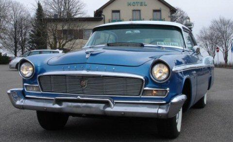
Expert
Posts: 1530
Location: ZH, Switzerland | Hello Serge
Thank you very much for this idea! I'll use it too. Thanks a lot.
Happy motoring!
Dieter |
|
| |
|
Board Moderator & Exner Expert 10K+
Posts: 13062
Location: Southern Sweden - Sturkö island | Another Serge special - recycling and preserving in one step |
|
| |
|
Expert
Posts: 1215
Location: SWITZERLAND | Emblem on Door Panel: On many previous cars I owned, I liked the variety of the emblems. This is as well with FWL-Cars. But what I was always missing, an emblem on the door panel of the 1959 Dodge Custom Royal.. I purchased gloove box doors of Coronets, where there is an emblem exactly complying to my demands. Now it looks as original, as it was designed for. Another "Royal" eye-catcher. - SERGE -
Edited by sermey 2011-03-20 2:42 PM
 (DSC04544 Emblem Door Panel1 LL.jpg) (DSC04544 Emblem Door Panel1 LL.jpg)
 (DSC04546 Emblem Door Panel2 LL.jpg) (DSC04546 Emblem Door Panel2 LL.jpg)
Attachments
----------------
DSC04544 Emblem Door Panel1 LL.jpg (76KB - 761 downloads)
DSC04546 Emblem Door Panel2 LL.jpg (76KB - 742 downloads)
|
|
| |
|
Expert
Posts: 1215
Location: SWITZERLAND | Door Panels: A 3mm, pressed material is used, cut the contour according the door (the lines are not parallel or rectangular!), drill the holes and openings for handle, switches, clamps. Coat all the panel with a premium to be waterproof. Bostitch a protective pad behind the clamps position, then cover all the panel with a soft 3mm padding material as used for upholstery (not foamed rubber!) and fix it with contact spray. Now comes the vinyl (no glue at all!), just bostitch around on backside and on front under the mouldings, first a few ones, finally all around when adjusted. The Door Panel is now ready for mount, not seeing the fixing clamps at all. Same nice job for the other panels. - SERGE -
Edited by sermey 2011-03-27 12:26 PM
 (01 Right Door Panel Front View.jpg) (01 Right Door Panel Front View.jpg)
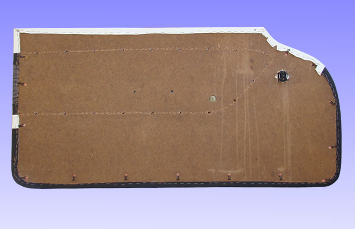 (02 Right Door Panel Rear View.jpg) (02 Right Door Panel Rear View.jpg)
 (03 Right Front Panel Ready.jpg) (03 Right Front Panel Ready.jpg)
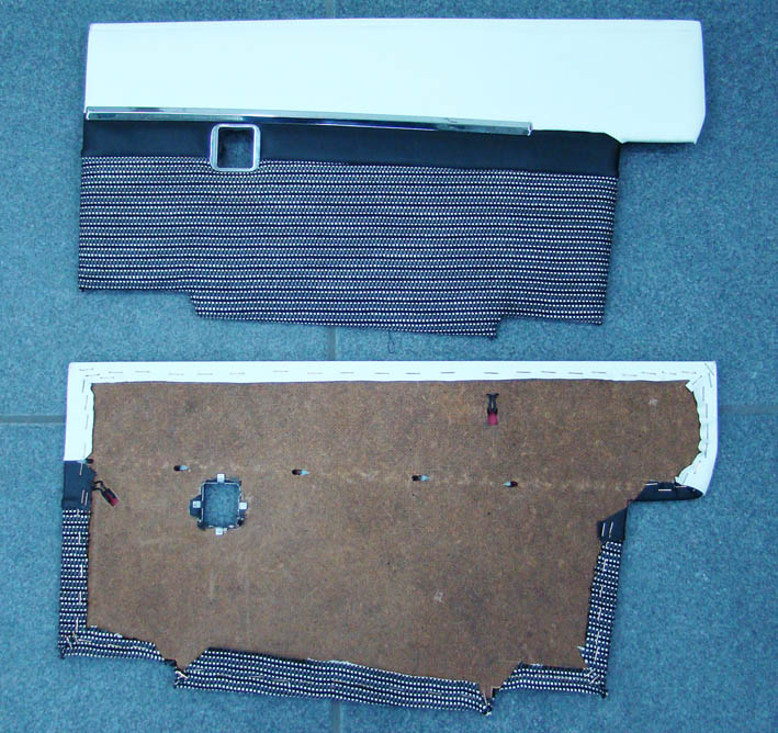 (04 Rear Side Panel Convertible.jpg) (04 Rear Side Panel Convertible.jpg)
Attachments
----------------
01 Right Door Panel Front View.jpg (39KB - 690 downloads)
02 Right Door Panel Rear View.jpg (60KB - 715 downloads)
03 Right Front Panel Ready.jpg (60KB - 735 downloads)
04 Rear Side Panel Convertible.jpg (141KB - 694 downloads)
|
|
| |
|
Expert
Posts: 1215
Location: SWITZERLAND |
Swapping the Door Moulding: When I got my car about 15 years ago, the rear and the door mouldings on the right side have been flatted at their common ends. No way to get some parts at this time, I had to restore them so as to be nearly invisible. Since then I found some of these very rare items. They are in stainless steel, doesn't rust or get pits, but as shown, hardly to restore when deformed. A punch by a door of another parked car - and it happened again!
At last, now I interchanged the door moulding and illustrate here how this is easy done when fixed as described earlier in http://www.forwardlook.net/forums/forums/thread-view.asp?tid=23691&start=51 , within a few minutes and no need of any special tools:
Push up the moulding and keep it back, push down and remove it. Due to the many riveted clamps pressing the moulding to the door, there are no gaps at all along. Finally the moulding can be fine adjusted by moving in height and side position. To replace the long rear moulding, the rear bumper has to be removed. This is fast servicing as is usual in todays cars. - SERGE -
Edited by sermey 2012-05-25 11:19 AM
 (1 - Restored Moulding to be replaced.jpg) (1 - Restored Moulding to be replaced.jpg)
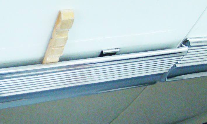 (2 - Push up and back.jpg) (2 - Push up and back.jpg)
 (3 - Push down and removal.jpg) (3 - Push down and removal.jpg)
 (4 - Riveted Clamps.jpg) (4 - Riveted Clamps.jpg)
 (5 - No Gaps at all.jpg) (5 - No Gaps at all.jpg)
 (6 - New Door Side Moulding.jpg) (6 - New Door Side Moulding.jpg)
Attachments
----------------
1 - Restored Moulding to be replaced.jpg (40KB - 645 downloads)
2 - Push up and back.jpg (56KB - 714 downloads)
3 - Push down and removal.jpg (62KB - 672 downloads)
4 - Riveted Clamps.jpg (46KB - 659 downloads)
5 - No Gaps at all.jpg (37KB - 646 downloads)
6 - New Door Side Moulding.jpg (66KB - 650 downloads)
|
|
| |
|
Board Moderator & Exner Expert 10K+
Posts: 13062
Location: Southern Sweden - Sturkö island | Hi Serge, nice to see your posts again! As always, very informative and sharing - with concern of our othere FL friends. Thanks for sharing! |
|
| |
|
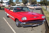
Elite Veteran
Posts: 1120
Location: Brisbane, Australia | G'day Serge thanks for the email and the link. some very ingenious solutions for FL owners
Cheers
Bob |
|
| |
|
Expert
Posts: 1215
Location: SWITZERLAND | Rear Power Windows Motor: The motor is just mounted on the removable panel with two screws. The big manual gear is turned so as to cover all the moving range of the windows lift. The position of the windows motor must be matched to the gear / theeth for the transmission. So, nearly any windows motor can be used. The wires goes under the sill plate. Easy for servicing or changing - and it works. - SERGE - -
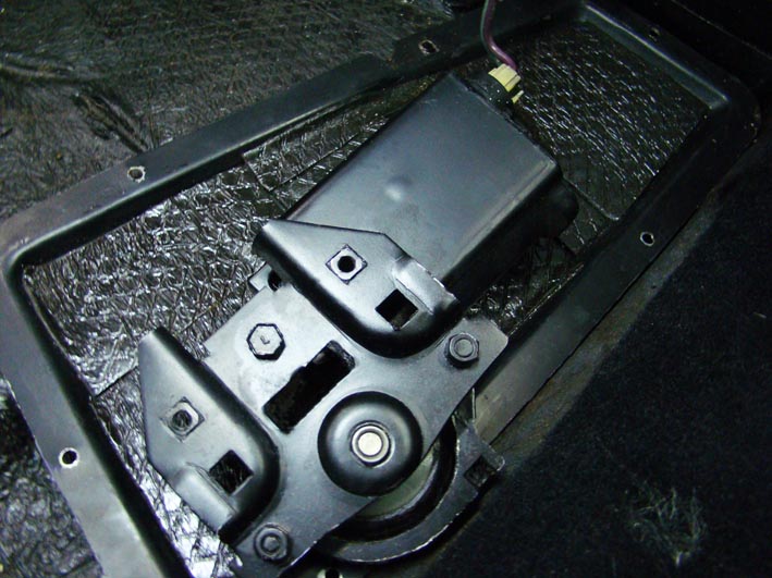 (1 - Rear Quarter Window Motor.jpg) (1 - Rear Quarter Window Motor.jpg)
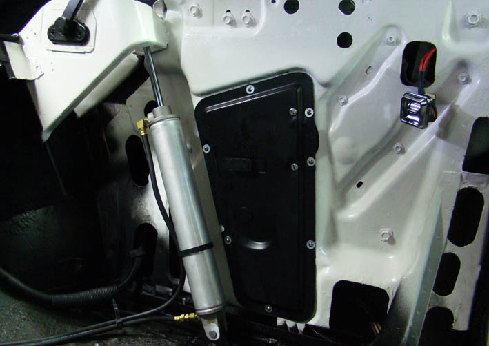 (2 - Rear Quarter Window Motor Mounted.jpg) (2 - Rear Quarter Window Motor Mounted.jpg)
Attachments
----------------
1 - Rear Quarter Window Motor.jpg (103KB - 636 downloads)
2 - Rear Quarter Window Motor Mounted.jpg (69KB - 672 downloads)
|
|
| |
|
Expert
Posts: 1215
Location: SWITZERLAND | Dual Oval Exhaust Tips: Long time I had the feeling, my Dual Round Exhaust Tips, as described earlier here, are too small for this big car. Looking around I found Stainless Oval Tips AMG Style 350 x 85 x 58 mm, slanted. The lenght fits exactly up to the exhausts suspension. They can be mounted without seeing
any screws, thus looks as original tubes. Furthermore, due to the distance of the oval shape to the inner round tube, the tips will not get any heat tinting. They have only to be cut-out to fit the mounting brackets.
When assembled, inserted and adjusted to the correct position, just tighten the two screws - that's all. Same inverse procedure for easy removing. Now my Dodge looks more powerful and sporty - a low cost visual power boost! :)
Edited by sermey 2012-05-28 2:32 AM
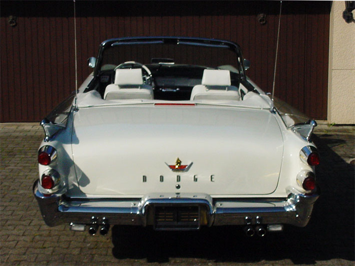 (1 - Round Exhaust Tips.jpg) (1 - Round Exhaust Tips.jpg)
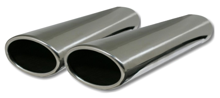 (2 - Oval Exhaust Tips Style AMG 350x85x58.jpg) (2 - Oval Exhaust Tips Style AMG 350x85x58.jpg)
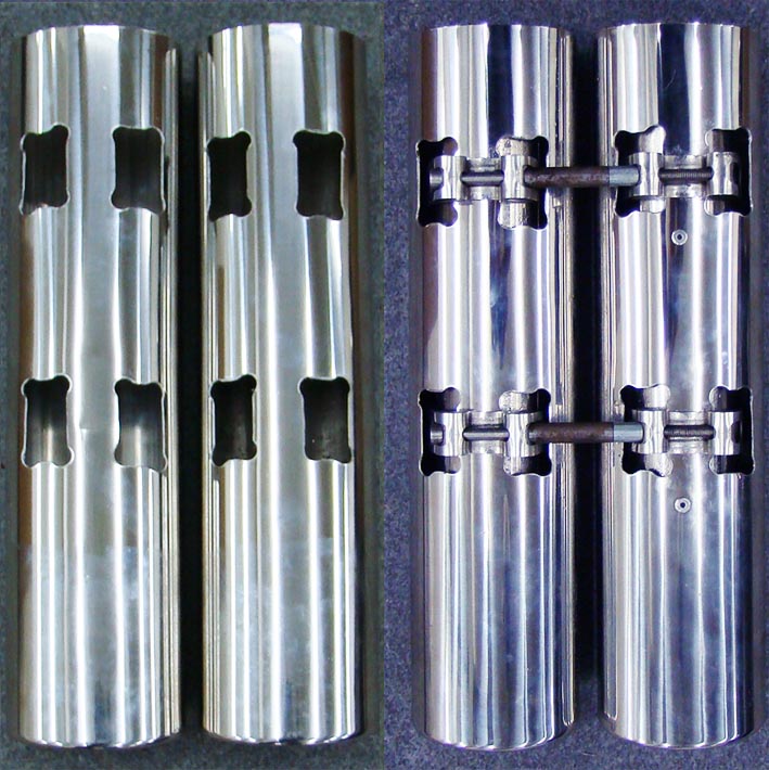 (3 - Dual Unit Cut and Assembled.jpg) (3 - Dual Unit Cut and Assembled.jpg)
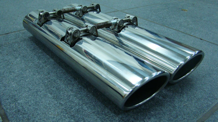 (4 - Unit Ready for Mounting.jpg) (4 - Unit Ready for Mounting.jpg)
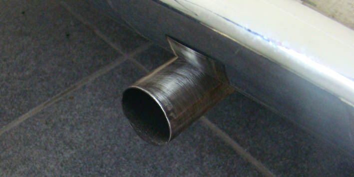 (5 - No Exhaust Tip.jpg) (5 - No Exhaust Tip.jpg)
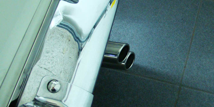 (6 - Insert Unit Vertically.jpg) (6 - Insert Unit Vertically.jpg)
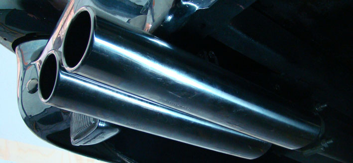 (7 - Push-in and Turn to Horizontal.jpg) (7 - Push-in and Turn to Horizontal.jpg)
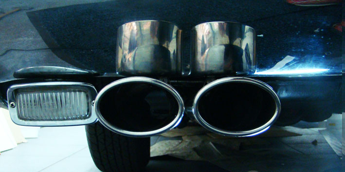 (8 - Adjust and Tighten 2 Screws.jpg) (8 - Adjust and Tighten 2 Screws.jpg)
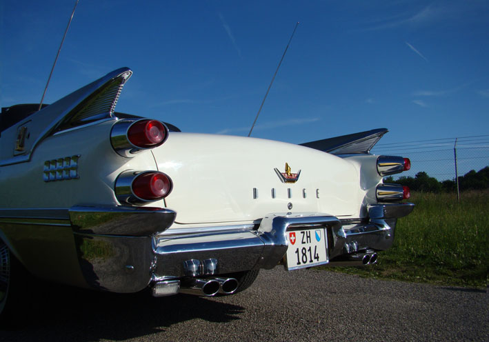 (9 - New Oval Exhaust Tips - Side View.jpg) (9 - New Oval Exhaust Tips - Side View.jpg)
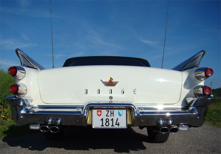 (10 - New Oval Exhaust Tips - Rear View.jpg) (10 - New Oval Exhaust Tips - Rear View.jpg)
Attachments
----------------
1 - Round Exhaust Tips.jpg (90KB - 683 downloads)
2 - Oval Exhaust Tips Style AMG 350x85x58.jpg (65KB - 663 downloads)
3 - Dual Unit Cut and Assembled.jpg (133KB - 687 downloads)
4 - Unit Ready for Mounting.jpg (96KB - 660 downloads)
5 - No Exhaust Tip.jpg (46KB - 664 downloads)
6 - Insert Unit Vertically.jpg (59KB - 667 downloads)
7 - Push-in and Turn to Horizontal.jpg (63KB - 672 downloads)
8 - Adjust and Tighten 2 Screws.jpg (73KB - 655 downloads)
9 - New Oval Exhaust Tips - Side View.jpg (82KB - 667 downloads)
10 - New Oval Exhaust Tips - Rear View.jpg (81KB - 669 downloads)
|
|
| |
|
Expert
Posts: 1215
Location: SWITZERLAND | Buzzer on Flasher: In addition to the earlier subject "Directional Flasher" in this thread here pictures of the final Flasher-Buzzer Unit as glued , connected and fixed with a clamp behind the radio (view from bottom). The buzzer is damped for lower alert with masking tape. Today I won't miss this option in my Convertible at all. - SERGE -
Edited by sermey 2012-05-29 10:47 AM
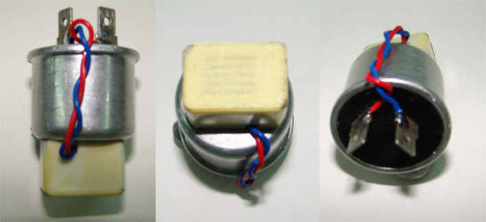 (1 - Flasher-Buzzer Unit - Various Views.jpg) (1 - Flasher-Buzzer Unit - Various Views.jpg)
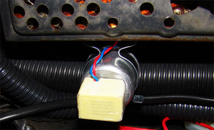 (2 - Flasher-Buzzer Unit fixed on Clamp behind Radio - Bottom View.jpg) (2 - Flasher-Buzzer Unit fixed on Clamp behind Radio - Bottom View.jpg)
Attachments
----------------
1 - Flasher-Buzzer Unit - Various Views.jpg (103KB - 684 downloads)
2 - Flasher-Buzzer Unit fixed on Clamp behind Radio - Bottom View.jpg (86KB - 684 downloads)
|
|
| |
|
Expert
Posts: 1215
Location: SWITZERLAND | sermey - 2012-05-29 4:37 PM Buzzer on Flasher: Explanatory comment This buzzer sounds intermittend with the directional light flashing. On the 1959 Dodge the indicator lamps on the instruments panel are hardly visible. Furthermore, the flasher unit doesn't sound enough to hear the directional light being flashing. Worst on the HighWay when entering at opened top. Then it happens that the flasher doesn't stop automatically and goes on flashing - can be dangerous for the driver as for others.
Now I hear when the flasher is active, the intermittend tone of the buzzer, corresponding to the directional lights, and don't have to check anymore the instruments panel. - SERGE - :laugh:
PS: Pay attention to the correct polarity of the buzzer connection! Edited by sermey 2012-05-31 12:52 AM
|
|
| |
|
Expert
Posts: 1215
Location: SWITZERLAND | sermey - 2012-05-30 10:34 PM sermey - 2012-05-29 4:37 PM Buzzer on Flasher: An earlier solution instead Many years ago I did another way to get the directional flasher more audible: Connect the output of the flasher directly to the radio loudspeaker, over a serial circuit of a capacitor and a resistor of more than 100 Ohm.
This doesn't influence the radio operation at all. The value of the capacitor determines the frequency band of the ticking, the resistor value the loudness. But I didn't liked this peakish ticking, I find the buzzer solution sounds more calming. But test it yourself. - SERGE - Edited by sermey 2012-05-31 7:27 AM
|
|
| |
|
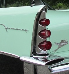
Expert
Posts: 2788
Location: USA - KY |
Dang! What a great thread, Serge! I vote that it becomes a "sticky'.
You have an incredible eye for detail, and the heart of an artist!
Fabulous car you have there!
Thank you for sharing your knowledge and experience.

Edited by FIN ME 2012-06-05 11:34 AM
|
|
| |
|
Board Moderator & Exner Expert 10K+
Posts: 13062
Location: Southern Sweden - Sturkö island | Yep, Serge's the man - I and so many others have learnt a lot of ways to improve and enhance our cars from him. |
|
| |
|
Expert
Posts: 1215
Location: SWITZERLAND | Soft Front Styling: A soft styling is only visible when direct comparing with the original. This should just accentuate or hide some style elements being part of its original design, not only on cars - this as well for Ladies! The front of the 1959 Dodge I find just a little bit bulky and massy in respect to the cars smooth lines. I tried to give to the overall front a wider and lighter aspect. On Photoshop I played on various designs. First the two long front bars have been cut in medium and short (Pic1) for lightening, then the verticals on the grille have been interrupted for widen, as well optically. I decided for the mid bar (Pic2), cut the bars accordingly, having a pair of spare for reversing. The new length of the chrome bar matches to the grill structure and the upper chrome moldings. The cut-out length is 78mm, must be done exact parallel to its end (Pic3). The end plates for mounting are easy removed by drilling holes where soldered. These holes then are used for fixing back the end to the shortened bar (4x M3). Now the bar can be mounted and aligned on the car as before (Pic4). To fix the center needs an additional metal extension due to the moved fixing plate. This Dodge now has got a soft face lifting (Pic5), appears to be wider and lighter – nice? - SERGE - To know: As usual this modification can be reversed at any time.
Edited by sermey 2012-06-06 9:11 AM
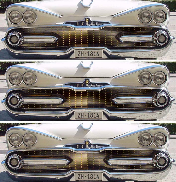 (1 - Test Chrome Bar Original - Medium - Short.jpg) (1 - Test Chrome Bar Original - Medium - Short.jpg)
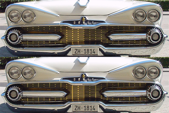 (2 - Comparison Before - After.jpg) (2 - Comparison Before - After.jpg)
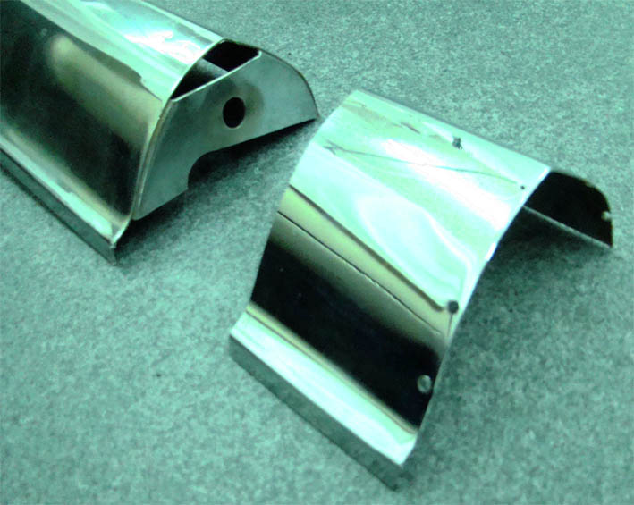 (3 - Cut Chrome Bar Medium.jpg) (3 - Cut Chrome Bar Medium.jpg)
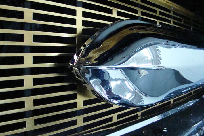 (4 - 59Dodge Chrome Bar Alignment.jpg) (4 - 59Dodge Chrome Bar Alignment.jpg)
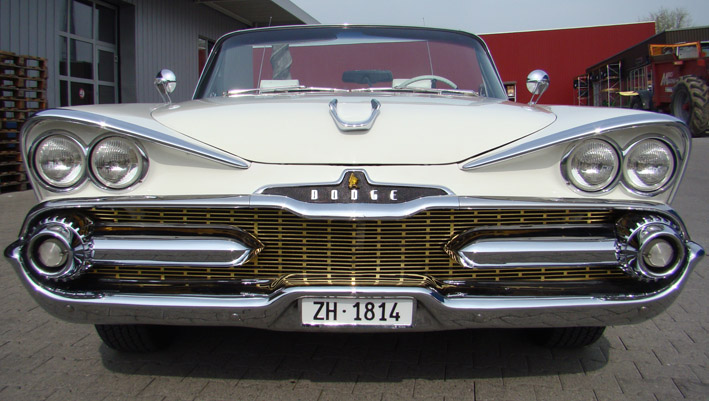 (5 - 59Dodge Front Softly Styled.jpg) (5 - 59Dodge Front Softly Styled.jpg)
Attachments
----------------
1 - Test Chrome Bar Original - Medium - Short.jpg (174KB - 806 downloads)
2 - Comparison Before - After.jpg (220KB - 679 downloads)
3 - Cut Chrome Bar Medium.jpg (83KB - 706 downloads)
4 - 59Dodge Chrome Bar Alignment.jpg (92KB - 693 downloads)
5 - 59Dodge Front Softly Styled.jpg (116KB - 682 downloads)
|
|
| |
|
Board Moderator & Exner Expert 10K+
Posts: 13062
Location: Southern Sweden - Sturkö island | See what I mean! Who else than Serge would dwell on an idea for a long time and realize it as his soft personalizing of the Exner design??!! To me, it looks more balanced and even give the car a wider look.
Also, totally reversible if he should change his mind. Yes, I really like it - who would even notice it in a car show? Some connoisseur might get a puzzled look and think, there's something about this car - others wont even note it! |
|
| |
|
Expert
Posts: 1215
Location: SWITZERLAND | Center Front Emblem 1: As I love emblems on cars, especially on the front, it was the logical consequence for me to experiment what emblem could fit, now as the front was stylistically enlarged. To give some ideas here are illustrated some steps, in two parts, how to get the final result, using tools as photoshop and CAD in combination.
1. D500 Emblem: Having a spare D500 Emblem, I mounted the picture with Photoshop (PS) on the center front. But I didn’t like. Furthermore, the golden knight is looking to the left, on the medaillon to the right. To see it correctly on the picture I turned the head to the right (01).
2. Resized Knight Head: Why not a Resized Knight Head, mirrored to be as well turned to the right? Two knights at a glance, and at different sizes I found too much and corny (02).
3. 500: Or just the numbers “500”, already existing for 1968 Dodge Coronet (03)? I modeled resized “500” keeping the style of the D500 Emblem (04)? On the car I found too narrow, too similar to the 1968 one (05).
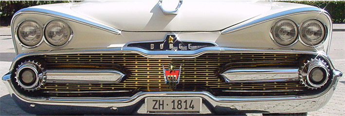 (01 - PS Front Emblem on Car - D500 Emblem.jpg) (01 - PS Front Emblem on Car - D500 Emblem.jpg)
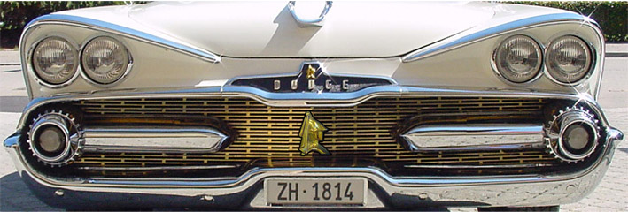 (02 - PS Front Emblem on Car - Resized Knight Head.jpg) (02 - PS Front Emblem on Car - Resized Knight Head.jpg)
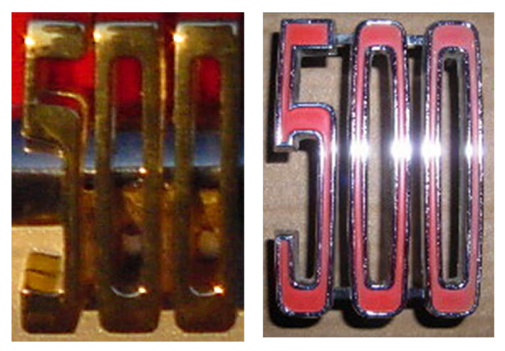 (03 - D500 and 500-68.jpg) (03 - D500 and 500-68.jpg)
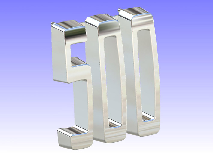 (04 - CAD Front Emblem Solo - 500 Style D500.jpg) (04 - CAD Front Emblem Solo - 500 Style D500.jpg)
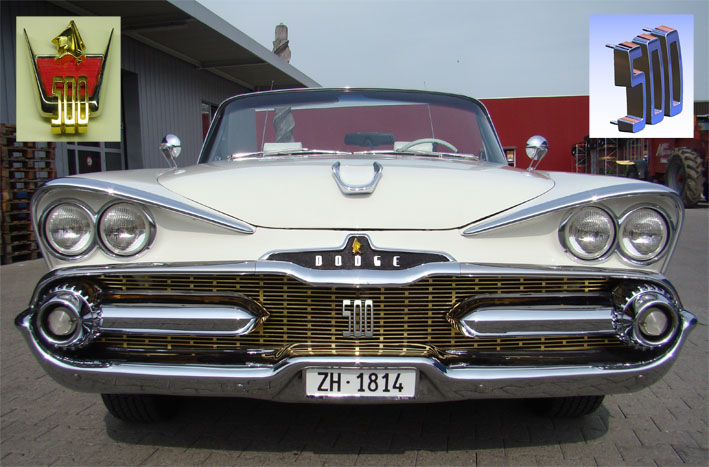 (05 - PS Front Emblem on Car - 500 Style D500.jpg) (05 - PS Front Emblem on Car - 500 Style D500.jpg)
Attachments
----------------
01 - PS Front Emblem on Car - D500 Emblem.jpg (95KB - 718 downloads)
02 - PS Front Emblem on Car - Resized Knight Head.jpg (94KB - 729 downloads)
03 - D500 and 500-68.jpg (78KB - 703 downloads)
04 - CAD Front Emblem Solo - 500 Style D500.jpg (50KB - 699 downloads)
05 - PS Front Emblem on Car - 500 Style D500.jpg (112KB - 665 downloads)
|
|
| |
|
Expert
Posts: 1215
Location: SWITZERLAND | Center Front Emblem 2:
4. “500” with font style of the front medaillon “DODGE”: To match the heavy chrome bars, the numbers are extruded with a slightly conical thickness (06). Inserted on the car with Photoshop as check gives a near original impression (07). Finally I decided to manufacture these numbers.
Using a STEP-File built from the model, a mechanical workshop cut the numbers directly, out of an aluminium-bloc, without the need any dimensions (08). The fixing bolts have been placed in order to fit between the gaps of the grille (M4). Thus there is no need of any modification or drilling (08). I did two sets at once. The one Golden coated I mounted first on the car, and the other I let Rechrome.
Golden I found too excessive (09)(10)(11). Only old ladies may wear a lot of gold – not a 1959 Dodge! Thus I swapped to the 500 Chrome version (12)(13)(14).
On the podest, at the last car meeting, the “outsider” speaker announced surprisingly: ”This is a DODGE 500”. -> No – this is just a unique, personalized 1959 DODGE! - SERGE - 
Edited by sermey 2012-06-18 6:36 AM
 (06 - CAD Front Emblem Solo - 500 Style Front Medaillon.jpg) (06 - CAD Front Emblem Solo - 500 Style Front Medaillon.jpg)
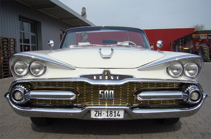 (07 - PS Front Emblem on Car - 500 Style Front Medaillon.jpg) (07 - PS Front Emblem on Car - 500 Style Front Medaillon.jpg)
 (08 - Emblem Manufactured in Aluminium Rechromed.jpg) (08 - Emblem Manufactured in Aluminium Rechromed.jpg)
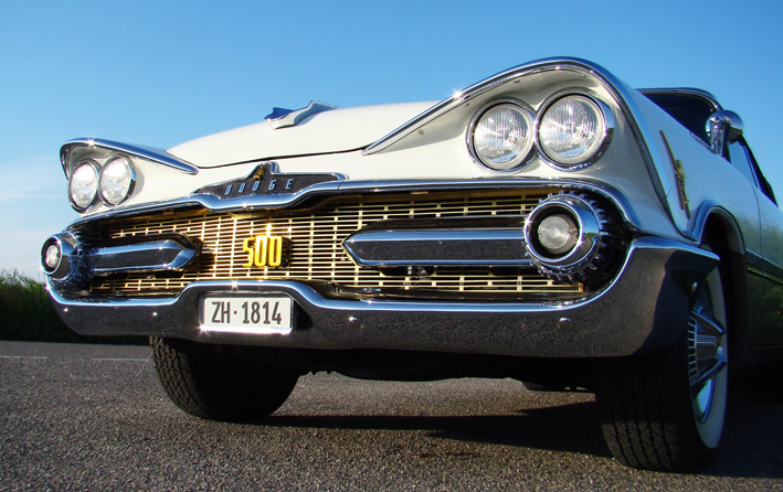 (09 - Front Emblem 500 Golden - Side View.jpg) (09 - Front Emblem 500 Golden - Side View.jpg)
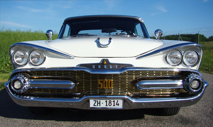 (10 - Front Emblem 500 Golden - Front View.jpg) (10 - Front Emblem 500 Golden - Front View.jpg)
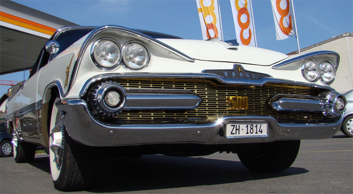 (11 - Front Emblem 500 Golden.jpg) (11 - Front Emblem 500 Golden.jpg)
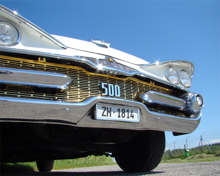 (12 - Front Emblem 500 Chrome - Side View.jpg) (12 - Front Emblem 500 Chrome - Side View.jpg)
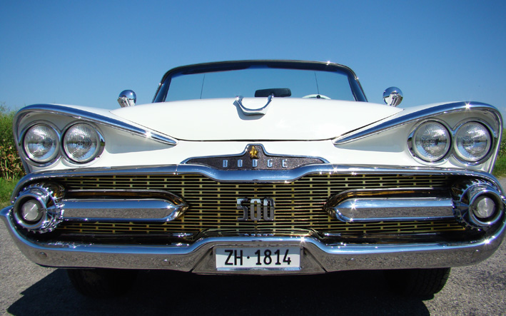 (13 - Front Emblem 500 Chrome - Front View.jpg) (13 - Front Emblem 500 Chrome - Front View.jpg)
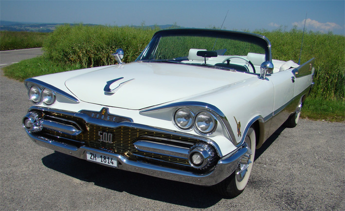 (14 - Front Emblem 500 Chrome.jpg) (14 - Front Emblem 500 Chrome.jpg)
Attachments
----------------
06 - CAD Front Emblem Solo - 500 Style Front Medaillon.jpg (65KB - 687 downloads)
07 - PS Front Emblem on Car - 500 Style Front Medaillon.jpg (130KB - 699 downloads)
08 - Emblem Manufactured in Aluminium Rechromed.jpg (83KB - 662 downloads)
09 - Front Emblem 500 Golden - Side View.jpg (135KB - 684 downloads)
10 - Front Emblem 500 Golden - Front View.jpg (111KB - 718 downloads)
11 - Front Emblem 500 Golden.jpg (144KB - 673 downloads)
12 - Front Emblem 500 Chrome - Side View.jpg (145KB - 682 downloads)
13 - Front Emblem 500 Chrome - Front View.jpg (150KB - 682 downloads)
14 - Front Emblem 500 Chrome.jpg (170KB - 860 downloads)
|
|
| |
|
Board Moderator & Exner Expert 10K+
Posts: 13062
Location: Southern Sweden - Sturkö island | Looks really good Serge - you finally realized the ideas you had for a long time!! This is really a very interesting way of personalize a car and still be able to go back to original whenever one wants to. Careful planning, testing and testing again the ideas digitally and the fabrication and realizing the dream.. |
|
| |
|
Expert
Posts: 1215
Location: SWITZERLAND | I know, many will dislike this, keeping strictly all as Original. Of course, if I will feel same one day, I will switch all back - a much shorter project! For a “maximum personalization” of my car I should model my original ancestors MEYER Emblem, dated 1756 (Birthyear of Mozart). Interesting fact: this hand-made Emblem has a Diameter of 175.6 mm ! ! !
Edited by sermey 2012-06-19 12:23 AM
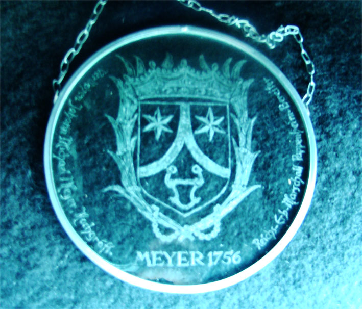 (Annum 1756 MEYER .jpg) (Annum 1756 MEYER .jpg)
Attachments
----------------
Annum 1756 MEYER .jpg (141KB - 682 downloads)
|
|
| |
|
Expert
Posts: 1215
Location: SWITZERLAND | Dual Remote Outside Rear View Mirrors: The option of a remote rear view mirror is not exceptional enough to comment here. Other a remote controlled mirror on the passenger side. Here I show how I got it working.
As I decided for this missing option on my car, I purchased 1959 / 1960 mirrors, harder to find than all other Mopar types. The mirrors I got had all more or less visible pits or speckles, and couldn’t satisfy the demands for my car, even they were praised to be “very nice”. When I got total five of them, four with remote and one without, I had no other choice to restore them. Now it was obvious to install a remote one as well on the passenger side, as an exceptional feature.
1. The body: Outside mirrors are for a viewer most exposed items - a bad one would affect an overall positive impression. Thus, they should present as jewels.
When the mirrors were disassembled, first the old chrome was removed. Then punched-out the pits as already described earlier (01), and the geometry of the surfaces restored. For finishing the conical parts and the round mirror housings, fixing items were necessary -> a polishing tool and a spray cap (02) to fix them on the driller (03). Now all parts have become ready to be copper-plated (04). With the fine polishing at home (!), nickel- and chrome-plating externally, the bodies have become ready for assembling.
2. The control wire: I found Nylon covered multi strand stainless wire (05), for minimum friction needed in the longer control line (180cm), and matching the specs of the original wire (D 0.85mm / 30kp breaking strength). The difference of the wires is shown in (06). On the rear of the mirror, additional holes are drilled, enabling to swap the wires and fix them as original by a node (07). These holes then are closed with plastic plugs, and all looks again as it should be (08).
(will be continued)
Edited by sermey 2012-06-18 10:58 AM
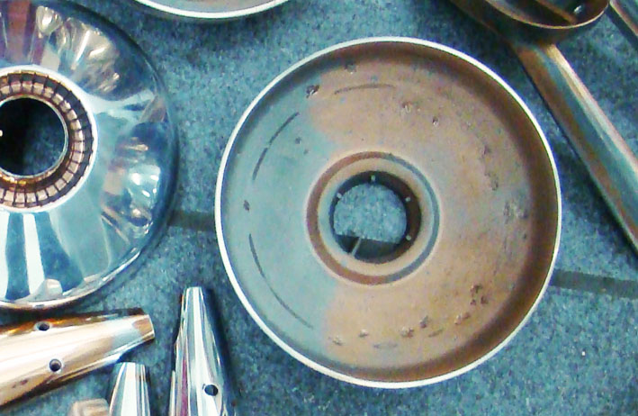 (01 - Punched-out pits.jpg) (01 - Punched-out pits.jpg)
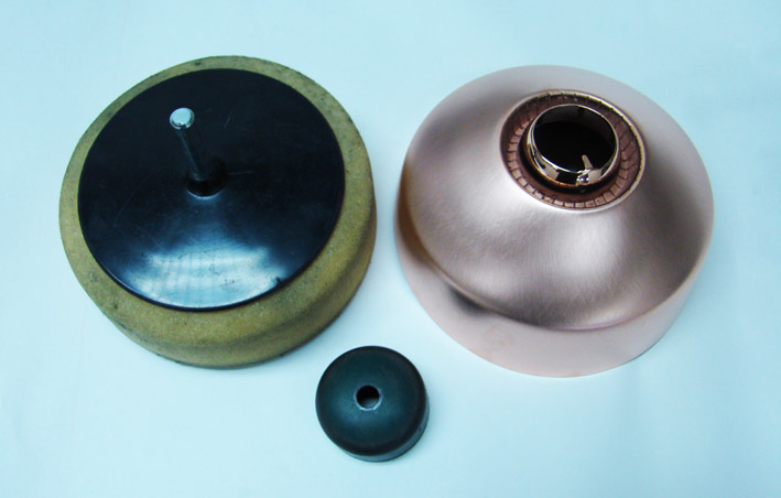 (02 - Fixing items.jpg) (02 - Fixing items.jpg)
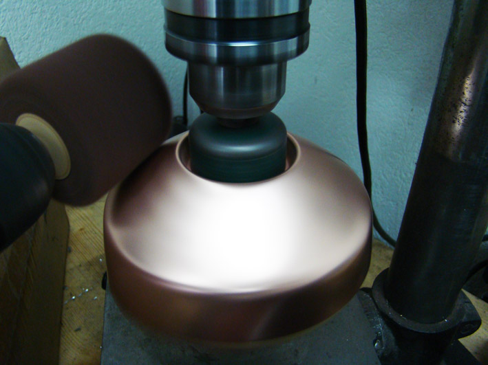 (03 - Fine grinding the surface.jpg) (03 - Fine grinding the surface.jpg)
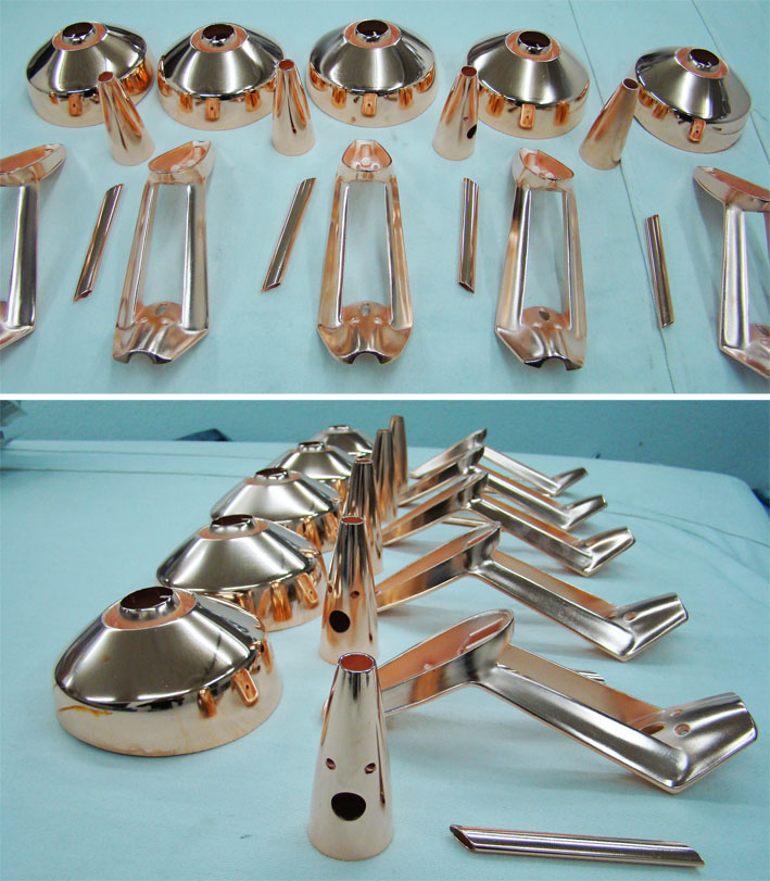 (04 - Restored bodies ready for copper plate.jpg) (04 - Restored bodies ready for copper plate.jpg)
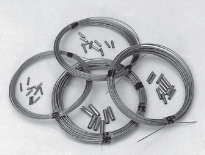 (05 - Nylon covered multi strand Stainless Wire.jpg) (05 - Nylon covered multi strand Stainless Wire.jpg)
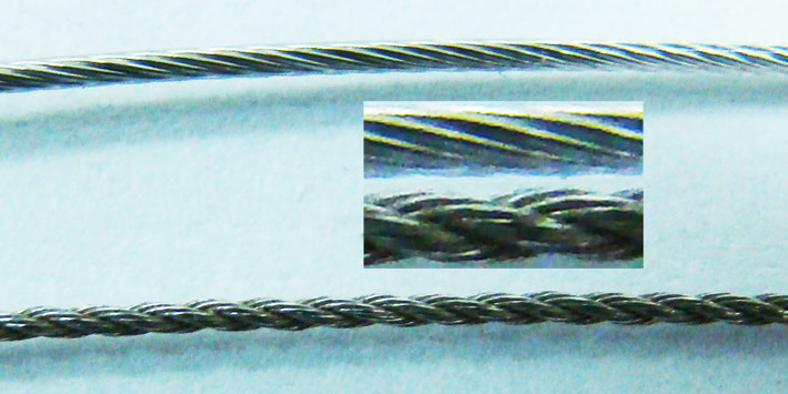 (06 - Comparison Original to coated Stainless Wire.jpg) (06 - Comparison Original to coated Stainless Wire.jpg)
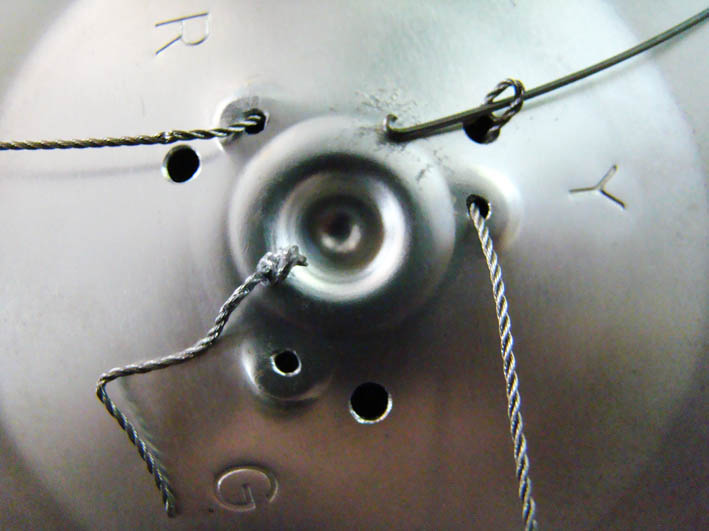 (07 - Swapping the wires in the mirror.jpg) (07 - Swapping the wires in the mirror.jpg)
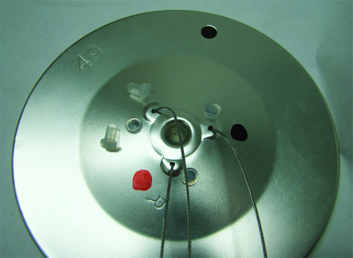 (08 - New wires and holes plugged.jpg) (08 - New wires and holes plugged.jpg)
Attachments
----------------
01 - Punched-out pits.jpg (114KB - 677 downloads)
02 - Fixing items.jpg (69KB - 720 downloads)
03 - Fine grinding the surface.jpg (95KB - 678 downloads)
04 - Restored bodies ready for copper plate.jpg (160KB - 741 downloads)
05 - Nylon covered multi strand Stainless Wire.jpg (111KB - 669 downloads)
06 - Comparison Original to coated Stainless Wire.jpg (91KB - 685 downloads)
07 - Swapping the wires in the mirror.jpg (62KB - 727 downloads)
08 - New wires and holes plugged.jpg (94KB - 721 downloads)
|
|
| |
|
Board Moderator & Exner Expert 10K+
Posts: 13062
Location: Southern Sweden - Sturkö island | I really like the idea with the sanding disk - smart one! Did you send the mirrors to a chrome shop for to de-chrome them? Also the new wires is interesting!! |
|
| |
|
Expert
Posts: 1215
Location: SWITZERLAND | Dual Remote Outside Rear View Mirrors: (2) 3. The steel shell: I couldn’t find steel shells thin enough to pass through the oval tube in the stand. I repaired and joined segments of an obsolete old mirror to the short one, with thin connection tubes used in the electronics (09). The steel shell must fit exactly face to face, no use of glue, then turned them inside together. If needed fix them by a heat shrinking tube. The extended three steel shells (170cm) are fixed tight together to a solid flexible unit (10). The silicon tube (8mm), is previously expanded in nitro solution (30 min) for easy inserting. This highly flexible tube, sustaining up to 180deg, protects the control wires from water and diminishes slippage when adjusting the mirror from one side to the other. Now the remote controlled mirror for the passenger side can be assembled to be ready for mounting, the joints can be seen on the picture (11).
4. The control line: Searching for the shortest line to the dashboard I found best to pass behind the hood hinge, this as well for the driver side. I modified the shaft of a conical drilling tool to fit a 1/4" adapter (12). With some 1/4" extensions I could easy widen the hole up to 20mm to fit a rubber protector, where the fixing plug of the interior isolation was previously removed (13). Now the control wires behind the hood hinge are much shorter, hardly visible and in a heat protected place (14).
(will be continued)
Edited by sermey 2012-06-19 4:28 AM
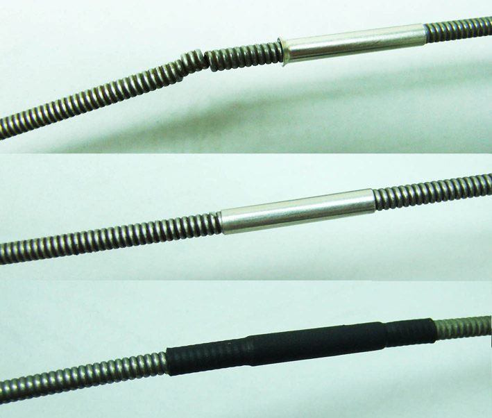 (09 - Repairing - Extending the steel shell.jpg) (09 - Repairing - Extending the steel shell.jpg)
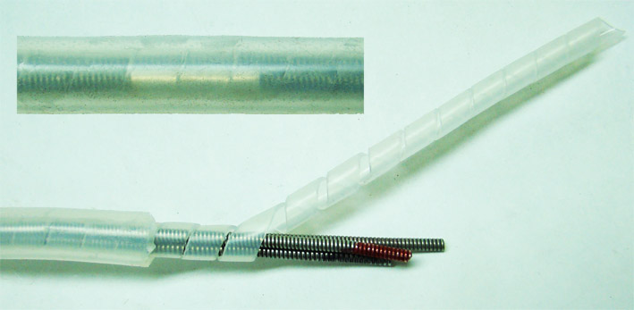 (10 - Fix the three steel shells.jpg) (10 - Fix the three steel shells.jpg)
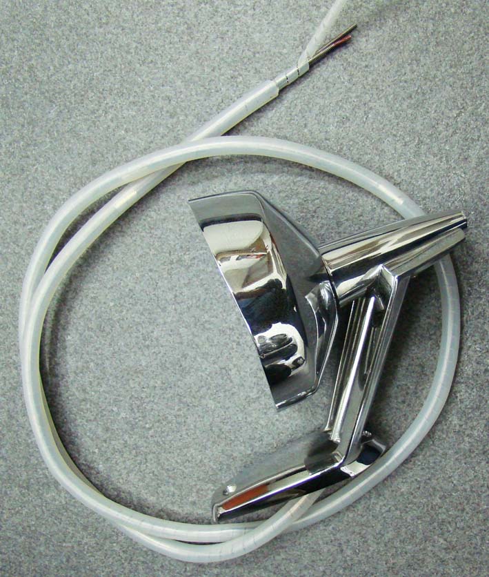 (11 - Passenger remote mirror assembled.jpg) (11 - Passenger remote mirror assembled.jpg)
 (12 - Drilling tool to fit 025 adapter.jpg) (12 - Drilling tool to fit 025 adapter.jpg)
 (13 - Drilling tool assembly.jpg) (13 - Drilling tool assembly.jpg)
 (14 - View control wires behind hood hinge.jpg) (14 - View control wires behind hood hinge.jpg)
Attachments
----------------
09 - Repairing - Extending the steel shell.jpg (95KB - 825 downloads)
10 - Fix the three steel shells.jpg (55KB - 820 downloads)
11 - Passenger remote mirror assembled.jpg (133KB - 772 downloads)
12 - Drilling tool to fit 025 adapter.jpg (64KB - 849 downloads)
13 - Drilling tool assembly.jpg (67KB - 810 downloads)
14 - View control wires behind hood hinge.jpg (71KB - 853 downloads)
|
|
| |
|
Expert
Posts: 1215
Location: SWITZERLAND | Power Window Connectors: For a good function of the power windows, the supply current should flow with minimum resistance, to assure a fast lifting: adequate wire diameter, soldered and cleaned connectors. A few pictures illustrates how this can be done. It is sufficient to label only the +12V wire (black marked), for all other wires can easily be changed, thanks the external additional (soldered) crimp-connectors (blue) in pic 07. – SERGE -
Edited by sermey 2012-06-20 7:58 AM
 (01 - Single connector soldered.jpg) (01 - Single connector soldered.jpg)
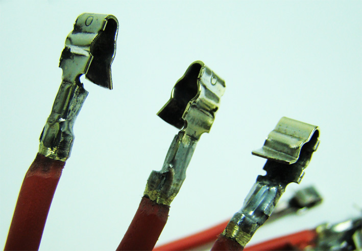 (02 - Multiple connectors soldered .jpg) (02 - Multiple connectors soldered .jpg)
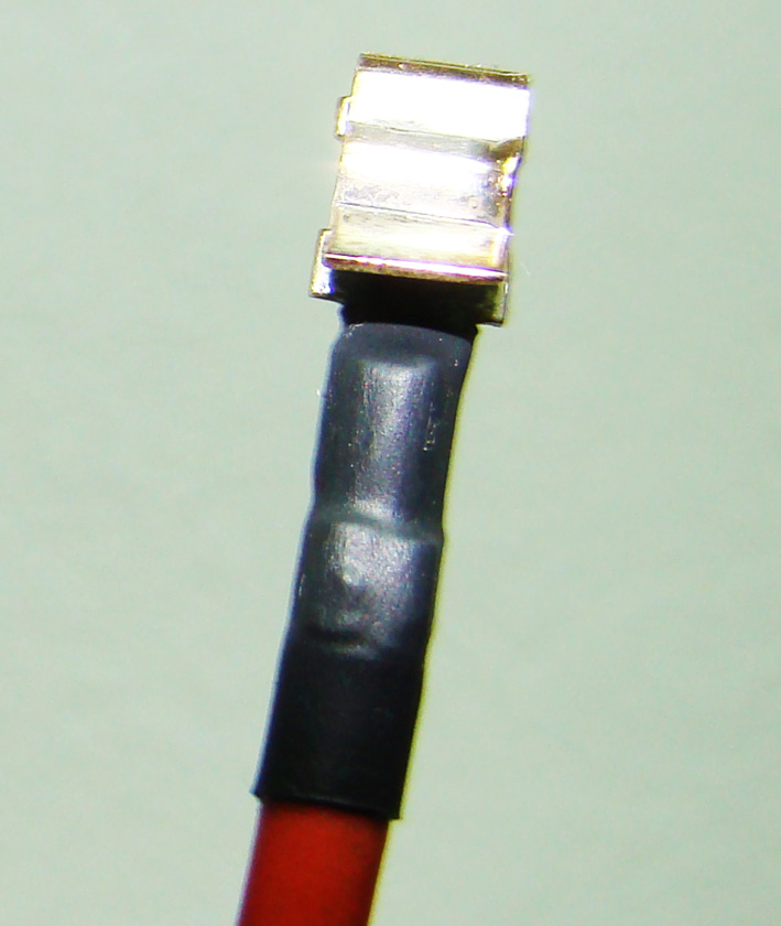 (03 - Single connector heat-shrinked tube.jpg) (03 - Single connector heat-shrinked tube.jpg)
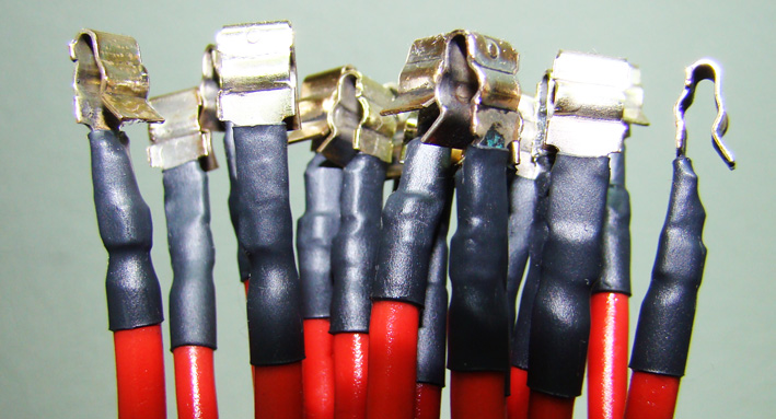 (04 - All Connectors with heat-shrinked tubes.jpg) (04 - All Connectors with heat-shrinked tubes.jpg)
 (05 - Connectors mounted.jpg) (05 - Connectors mounted.jpg)
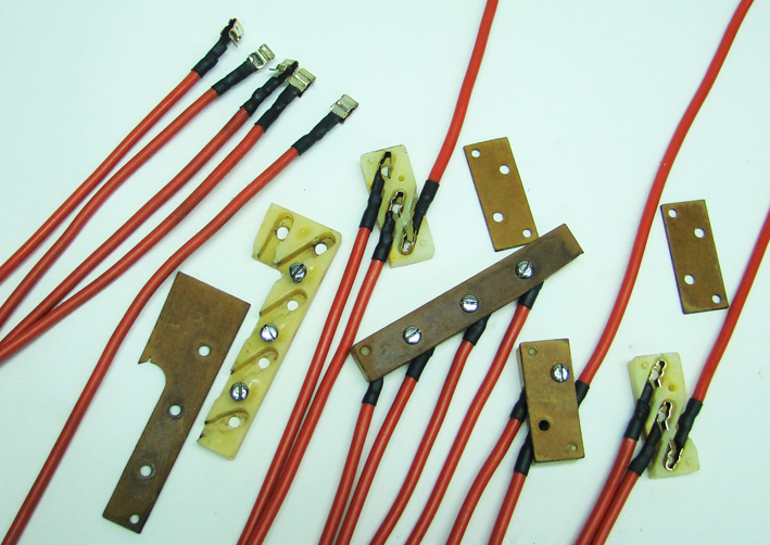 (06 - All Connector Parts - 4 Windows.jpg) (06 - All Connector Parts - 4 Windows.jpg)
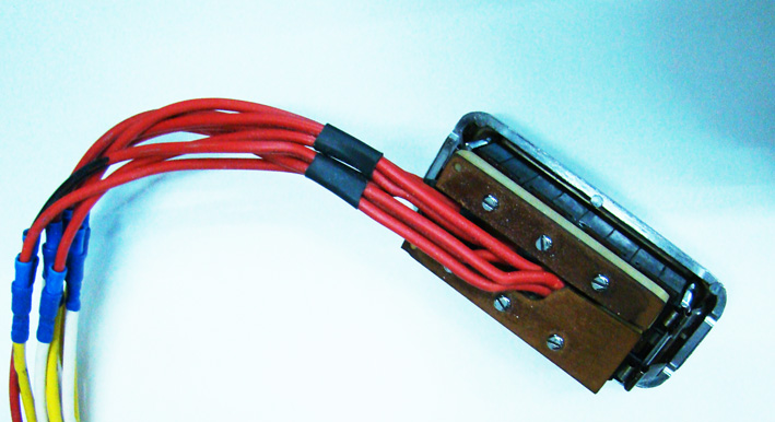 (07 - Assembled power window switch.jpg) (07 - Assembled power window switch.jpg)
Attachments
----------------
01 - Single connector soldered.jpg (101KB - 843 downloads)
02 - Multiple connectors soldered .jpg (103KB - 814 downloads)
03 - Single connector heat-shrinked tube.jpg (122KB - 838 downloads)
04 - All Connectors with heat-shrinked tubes.jpg (135KB - 798 downloads)
05 - Connectors mounted.jpg (98KB - 778 downloads)
06 - All Connector Parts - 4 Windows.jpg (169KB - 974 downloads)
07 - Assembled power window switch.jpg (113KB - 800 downloads)
|
|
| |
|
Expert
Posts: 1215
Location: SWITZERLAND | Dual Remote Outside Rear View Mirrors: (3) 5. The gasket: After the body of the mirror has been assembled and connected to the control line, it can be mounted on the fender, still without the mirror-glass. Although I got gaskets, I preferred to use my system as described earlier here. This gasket can be inserted without removing the mirror and the three control wires, and easy replaced at any time. It is thick enough not to leave impressions in the paint, and fits as custom-made. This is a Silicon-Rubber profile, as I used as well for the dual rear antennas, cut in the correct length (circonference of the stand). The ends are glued together to a fixed ring (15). Unscrew the mirror, so as the profile can be inserted and pushed-in (16). When the gasket fits all around, then tighten the screws (17). 6. The wire attachment: The described operations may be very usefull for those who have to repair their remote mirror. First of all, the three wires already fixed to the glass now must be inserted through the shell. To get the correct length the glass has to be fixed fully inside the body, to assure a sufficient tension to hold the mirror-glass at the end (18). Due to the nickel-chrome alloy, the wire cannot be soft soldered. For a solid attachment crimping sleeves are needed, as is original. For this purpose I used standard rivets, D 4mm, L 5.5mm (19). Before removing the nail, the diameter of the rivets head should be reduced from 7.5mm to 6.5mm in order to fit to the control unit (20). The end of the flexible control wire is bent to be better fixed when crimped, using a standard AMP tool (21). Take care to correct diameter for crimping, or the rivet may not fit anymore to the control unit (22)! Now the wires can easily be attached (23). To know: the rivets cannot be removed after crimping. Can cut away, must restart with shortened shell and wire (-6mm). On the passenger side, these operations can be done outside the car, for the control wires are long enough to pass the small side window (24). (wiil be continued)
Edited by sermey 2012-06-21 12:28 PM
 (15 - Glueing the gasket profile to a ring.jpg) (15 - Glueing the gasket profile to a ring.jpg)
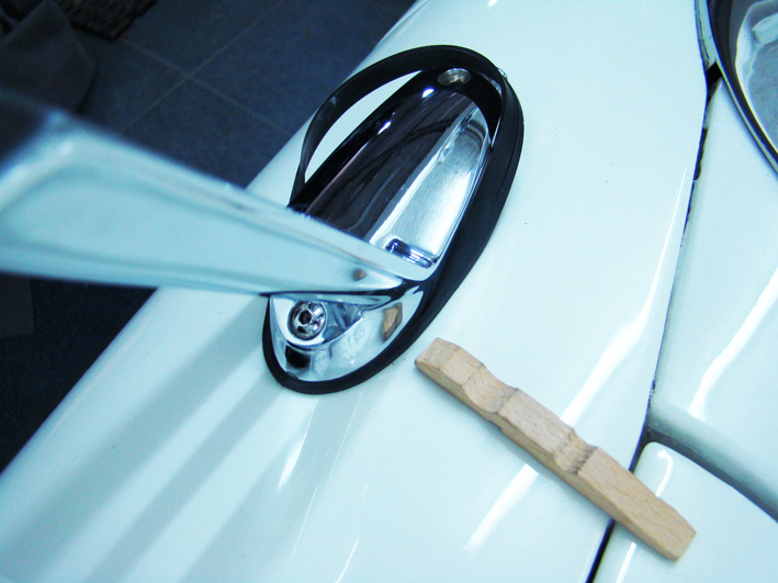 (16 - Pushing the gasket under the mirror stands .jpg) (16 - Pushing the gasket under the mirror stands .jpg)
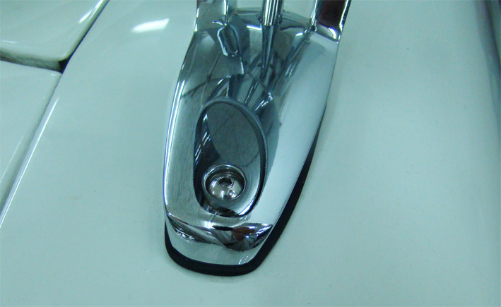 (17 - Mirror gasket fits all around.jpg) (17 - Mirror gasket fits all around.jpg)
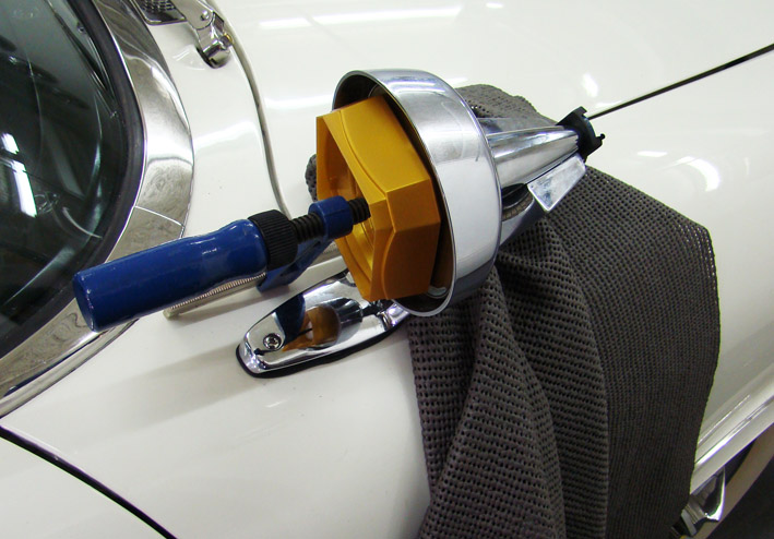 (18 - Fixing the glass.jpg) (18 - Fixing the glass.jpg)
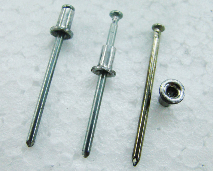 (19 - Preparing the rivets.jpg) (19 - Preparing the rivets.jpg)
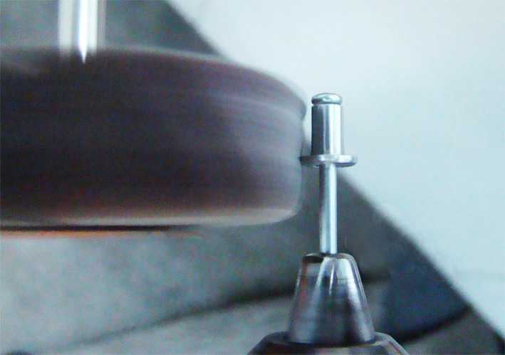 (20 - Reducing the rivets head diameter.jpg) (20 - Reducing the rivets head diameter.jpg)
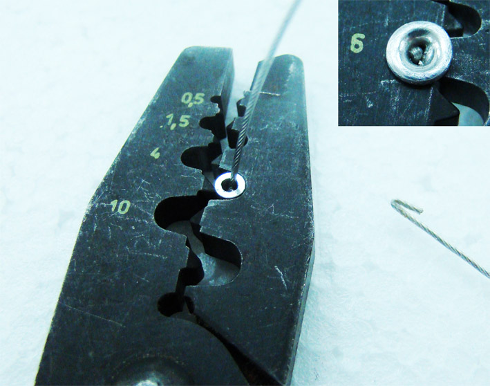 (21 - Crimping the wire.jpg) (21 - Crimping the wire.jpg)
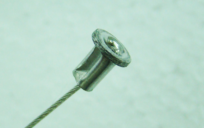 (22 - Control wire ready for attach.jpg) (22 - Control wire ready for attach.jpg)
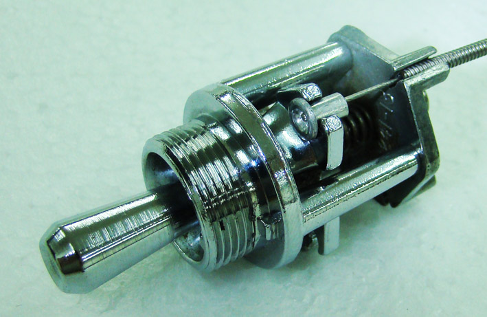 (23 - Wire attached to the control unit.jpg) (23 - Wire attached to the control unit.jpg)
 (24 - All control wires attached.jpg) (24 - All control wires attached.jpg)
Attachments
----------------
15 - Glueing the gasket profile to a ring.jpg (81KB - 820 downloads)
16 - Pushing the gasket under the mirror stands .jpg (131KB - 792 downloads)
17 - Mirror gasket fits all around.jpg (77KB - 777 downloads)
18 - Fixing the glass.jpg (115KB - 806 downloads)
19 - Preparing the rivets.jpg (111KB - 815 downloads)
20 - Reducing the rivets head diameter.jpg (101KB - 804 downloads)
21 - Crimping the wire.jpg (113KB - 775 downloads)
22 - Control wire ready for attach.jpg (73KB - 866 downloads)
23 - Wire attached to the control unit.jpg (110KB - 795 downloads)
24 - All control wires attached.jpg (92KB - 839 downloads)
|
|
| |
|
Expert
Posts: 1215
Location: SWITZERLAND | wizard - 2012-06-18 9:46 PM I really like the idea with the sanding disk - smart one! Did you send the mirrors to a chrome shop for to de-chrome them? Also the new wires is interesting!! Here how as I did all parts to be rechromed on my car: 1. Disassemble all items to single parts 2. Bring them to the galvanic shop for remove chrome and nickel. Old copper will partly be removed due to strongness of nickel-removal. 3. Restore items geometry by punching, grinding, . . . and pre-polish to get the control of the surfaces. 4. Bring them again to the galvanic-shop for copper-plating. Needs enough copper for last restoration. 5. Fine-grinding and polish the item (01). The rechromed part will exactly be shiny as it has been polished. 6. Bring to the galvanic shop for nickel-plate and chrome-plate. Looks as in 5., but now in "blue" chrome (02). When nice polished and rechromed, the mirror-effect should be sharp as from a glass-mirror (unfortunately my rugh ceiling is reflected, but some differences on the the Pic are apparent). If you can polish the items by yourself, you alone decide how nice the items will become. To know: from polishing you will get more black than from grease.
Edited by sermey 2012-06-25 3:24 PM
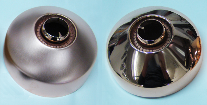 (01 - Copper fine grinded - copper polished.jpg) (01 - Copper fine grinded - copper polished.jpg)
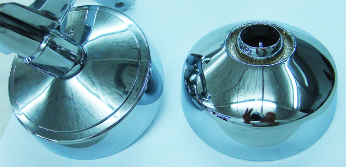 (02 - 1961 NOS mirror - 1959 Restored mirror.jpg) (02 - 1961 NOS mirror - 1959 Restored mirror.jpg)
Attachments
----------------
01 - Copper fine grinded - copper polished.jpg (149KB - 770 downloads)
02 - 1961 NOS mirror - 1959 Restored mirror.jpg (181KB - 976 downloads)
|
|
| |
|
Expert
Posts: 1215
Location: SWITZERLAND | Adjustment of the flasher: Here the proceeding, when the directional lamps flashes too fast. It is checked on a spare part I had, a bigger flasher, but the principle remains identical. This one flashed too fast, connected to my car. First remove the housing by grinding around till the lip-ring detache (01). Then bent the contact with a pince up (here I did it by hand), to increase the distance at opened contacts for a slower flashing. It must be the contact without bi-metal (zoomed), just about 0.1mm (02), must be checked. Finally fix back the metal housing using instant glue inside around (03). Can let the ignition and the blinking ON. just connect and disconnect the opened flasher for better handling, and put back for test. Don't hold at the contacts, only the socket!
Edited by sermey 2012-06-26 3:52 AM
 (01 - Opened flasher.jpg) (01 - Opened flasher.jpg)
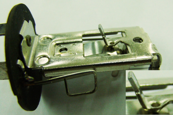 (02 - Contact to adjust.jpg) (02 - Contact to adjust.jpg)
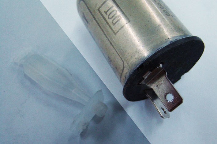 (03 - Instant glued metal housing.jpg) (03 - Instant glued metal housing.jpg)
Attachments
----------------
01 - Opened flasher.jpg (93KB - 788 downloads)
02 - Contact to adjust.jpg (102KB - 781 downloads)
03 - Instant glued metal housing.jpg (87KB - 755 downloads)
|
|
| |
|
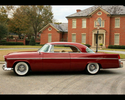
Expert
Posts: 1352
Location: Springville, CA | You can buy decent electronic flashers for less than $15 or $20. Their flash rates are controlled electronically and are not dependent on load. |
|
| |
|
Expert
Posts: 1215
Location: SWITZERLAND | 56Fanatic - 2012-06-26 3:41 PM You can buy decent electronic flashers for less than $15 or $20. Their flash rates are controlled electronically and are not dependent on load. This is a good advise, for I didn't know, unless it was to be expected. Do they sound when flashing as well?
Edited by sermey 2012-06-26 5:03 PM
|
|
| |
|
Expert
Posts: 1215
Location: SWITZERLAND | Dual Remote Outside Rear View Mirrors: (4) 7. The control unit: As my car didn’t was equipped with a remote mirror on the left fender I had to find out how and where to fix the control unit. Referring to pictures I built a bracket according the position where it should be. Later I found an instruments housing with the original bracket, included the delete plate (25). So I used the original one, as well the “MIRROR”-bezel (26). Other then original, the left hand control line behind the hinge now allows a straight and shorter connection. The right hand control unit was fixed with a chrome bezel, included with one mirror set, mounted exactly on the vertical under the left knob of the radio (27). This was the nearest available place, for other locations were already used. Here the control unit just not fit under the radio, the left lower corner of the housing has been slightly cut-out. The remote mirror on passenger side can now be adjusted by the driver, comfortable as the radio knob, while still keeping the rear view. 8. The final result. Due to the new Nylon covered multi strand stainless wire, the right side mirror with the much longer control line, is much slighter adjustable than the left side one. I will replace the old control wires as well. Finally I mounted the chrome bullets (28), fixed with M4 in the mirrors nut, as already described here: http://www.forwardlook.net/forums/forums/thread-view.asp?tid=23691&... A black rubber washer seals from entering water, and can be considered as an additional styling element (29). The two rear view mirrors, more sophisticated then the former ones, restored have now become: NT-NOS (= Nicer Than - New Old Stock). They underlines once more the exceptional art-work on forwardlook cars. Dual remote outside rear view mirrors, an additional exclusive feature on an outstanding 1959 Dodge Custom Royal Lancer Convertible. – SERGE -
Edited by sermey 2012-06-30 4:33 PM
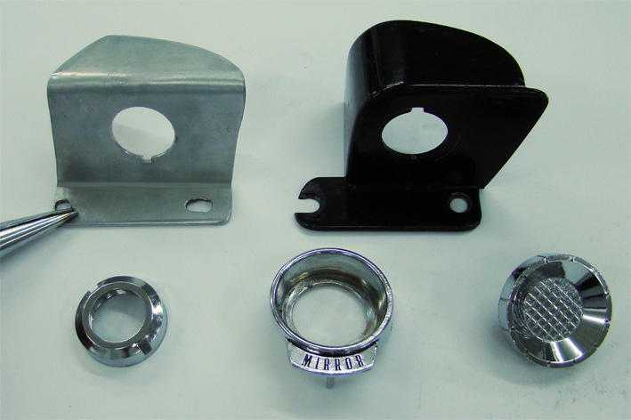 (25 - Left control bracket and delete plate.jpg) (25 - Left control bracket and delete plate.jpg)
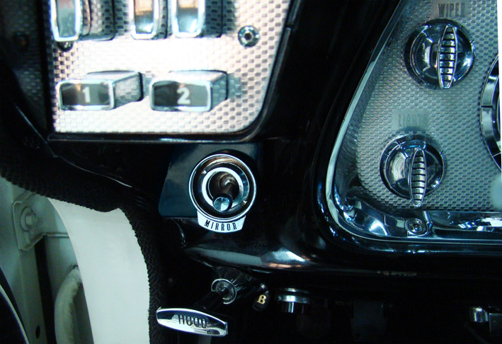 (26 - Left side mirror control.jpg) (26 - Left side mirror control.jpg)
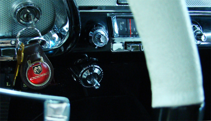 (27 - Right side mirror control.jpg) (27 - Right side mirror control.jpg)
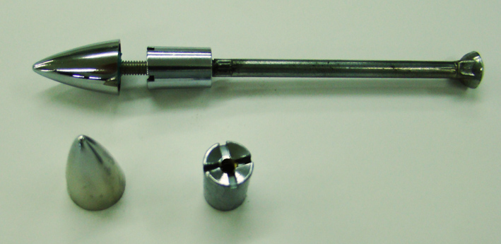 (28 - M4 in nut - bullet ready.jpg) (28 - M4 in nut - bullet ready.jpg)
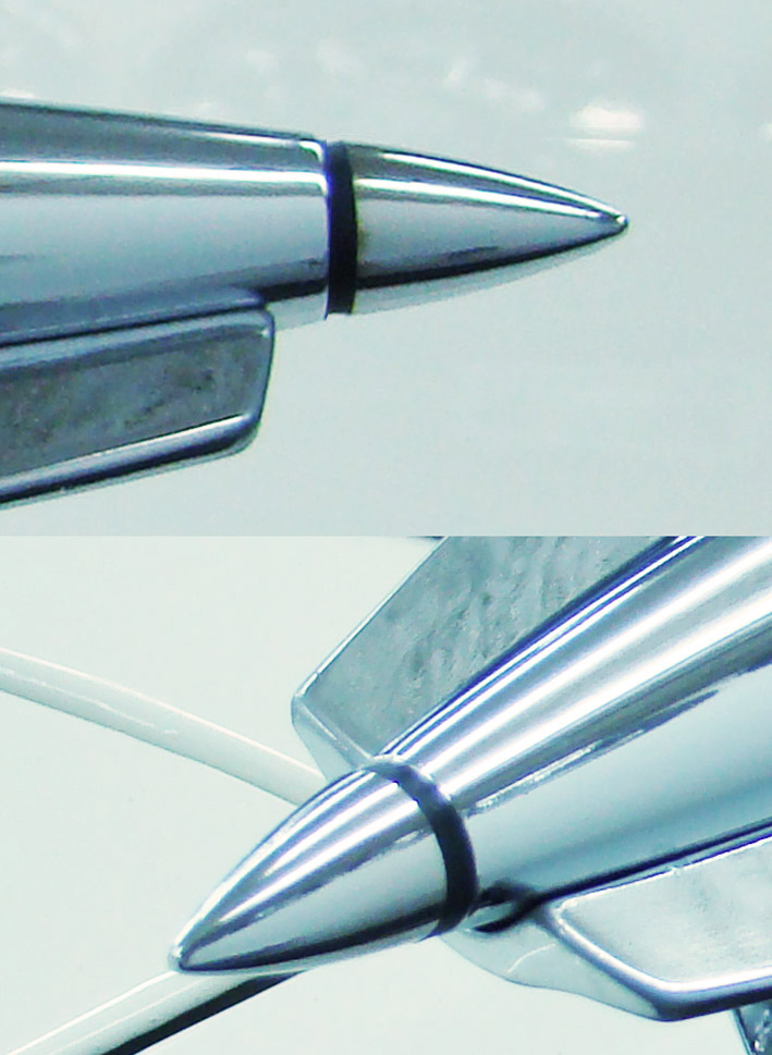 (29 - Mounted bullets.jpg) (29 - Mounted bullets.jpg)
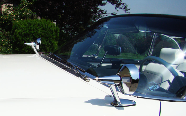 (30 - Restored rear view mirrors - NT-NOS.jpg) (30 - Restored rear view mirrors - NT-NOS.jpg)
Attachments
----------------
25 - Left control bracket and delete plate.jpg (107KB - 792 downloads)
26 - Left side mirror control.jpg (135KB - 829 downloads)
27 - Right side mirror control.jpg (139KB - 789 downloads)
28 - M4 in nut - bullet ready.jpg (110KB - 848 downloads)
29 - Mounted bullets.jpg (145KB - 782 downloads)
30 - Restored rear view mirrors - NT-NOS.jpg (136KB - 825 downloads)
|
|
| |
|
Extreme Veteran
Posts: 395
Location: Netherlands | Nice one Serge! Beautiful work! I too made a right hand remote controlled mirror, one of the first parts I made for our car.
I had a much easier job as we have the other type of twin strut mirror and I just combined several parts and used 2 sets of OEM cables.
They were connected to form the long cables with adjusters in the middle for fine-tuning the adjustment properties.
I won't spoil your beautiful thread with pics of my un-restored mirror set-up on an un-painted car... |
|
| |
|
Expert
Posts: 1215
Location: SWITZERLAND | Windsor Wendy - 2012-06-30 11:09 PM . . . used 2 sets of OEM cables. They were connected to form the long cables with adjusters in the middle for fine-tuning the adjustment properties. . . . You have as well a nice and intelligent approach, Wendy, my compliments! I will present a more easier way as those mentioned here: no need of 2 sets of OEM cables; the length of the wires also adjustables without needing to cut and re-crimp the rivets for the correct length: adjustment not in the middle of the cables, but at the end on the control unit. I will present this here as "Supplement" as soon I will have completed on my car and illustrate with pictures. - SERGE - Edited by sermey 2012-07-01 1:46 AM
|
|
| |
|
Expert
Posts: 1215
Location: SWITZERLAND | Head Lamp Bezel: When purchasing this item, the fixing clips are often rusty, broken or even missing (01). Before rechroming, they anyway have to be removed. Instead of these single metal clips, I used on each side two standard Nylon washers (D20 x d10.5 x t2mm) to fix the head lamp bezel. Metal washers are not flexible!
Grind the washer, flat on one side of its diameter, from D20mm to 18.5mm (or to d3.5mm distance to inner diameter) (02). Then, with a self-tapping stainless pan head screw (D2.85mm x 5.5mm), the Nylon washer can be fixed on the bezel (03). Due to the asymmetric grinded surface on one side, and to the geometric shape of the bezel on the other side, the washer cannot turn around and remains fixed, but still being flexible for mounting (03). Because of the originally uncentered threads of screw on the bezel, the Nylon washers have not the equal length, but this doesn't influence the function at all (04). A perfect Head Lamp Bezel you can see here: http://www.forwardlook.net/forums/forums/thread-view.asp?tid=34070&start=10
When needed, this is an instantly, simple and rustfree solution, and not scratching the paint when assembling. - SERGE - To Know: This Head Lamp Bezel is identical for the left and the right side. What you see here I did already 10 years ago, the Nylon washers have become a little bit yellow..
Edited by sermey 2012-07-05 3:54 PM
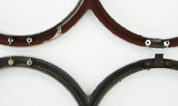 (01 - Missing Clips.jpg) (01 - Missing Clips.jpg)
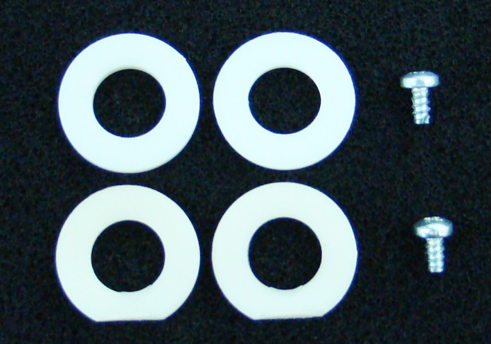 (02 - Nylon Washer Grinded.jpg) (02 - Nylon Washer Grinded.jpg)
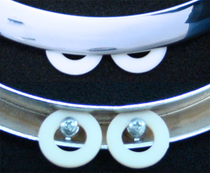 (03 - Mounted Nylon clips - Front Rear View.jpg) (03 - Mounted Nylon clips - Front Rear View.jpg)
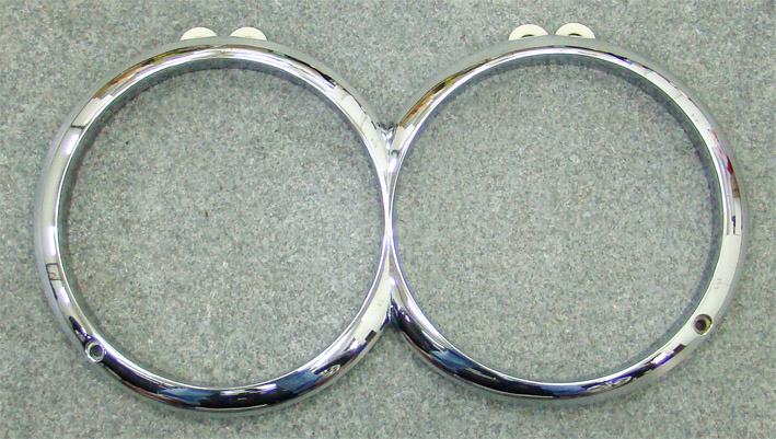 (04 - Bezel Front view Mounted Nylon Clips.jpg) (04 - Bezel Front view Mounted Nylon Clips.jpg)
Attachments
----------------
01 - Missing Clips.jpg (87KB - 817 downloads)
02 - Nylon Washer Grinded.jpg (133KB - 743 downloads)
03 - Mounted Nylon clips - Front Rear View.jpg (150KB - 785 downloads)
04 - Bezel Front view Mounted Nylon Clips.jpg (142KB - 758 downloads)
|
|
| |
|
Expert
Posts: 1215
Location: SWITZERLAND | Reminder: The solutions in this thread are NOT THE BEST ones. They show HOW I DID IT: logical, efficient and at all successfully approved on my car. - SERGE -  |
|
| |
|
Expert
Posts: 1215
Location: SWITZERLAND | Soft Front Styling: Supplement to http://www.forwardlook.net/forums/forums/thread-view.asp?tid=23691&start=144 I found some missing pictures commented here. The cutting line has equal distance (78mm) to the end, for keeping the original angle (3a). In the shortened chrome bar, four screw threads M4 (not M3!) are cut (3b). On the other side, the four Allen stainless screws are then shortened as needed (3c). As usual, it looks nice and solid.
Edited by sermey 2012-07-07 6:46 AM
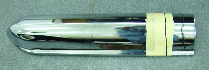 (3a - Cutting Line at equal Distance.jpg) (3a - Cutting Line at equal Distance.jpg)
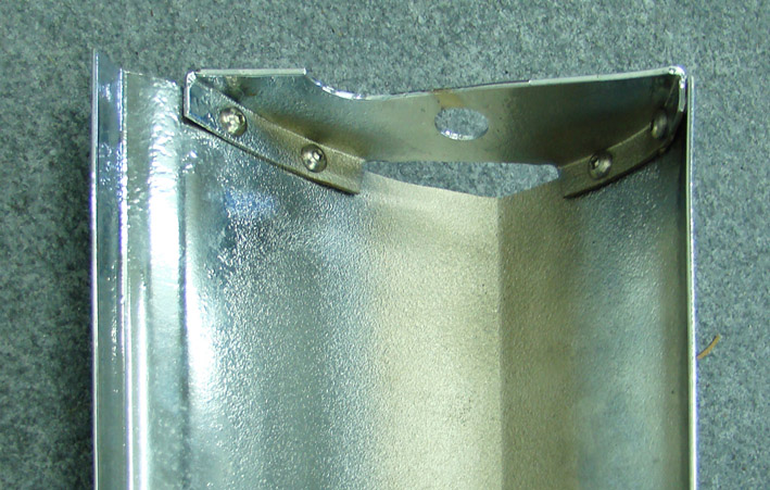 (3b - Mounted End Panel - Rear View.jpg) (3b - Mounted End Panel - Rear View.jpg)
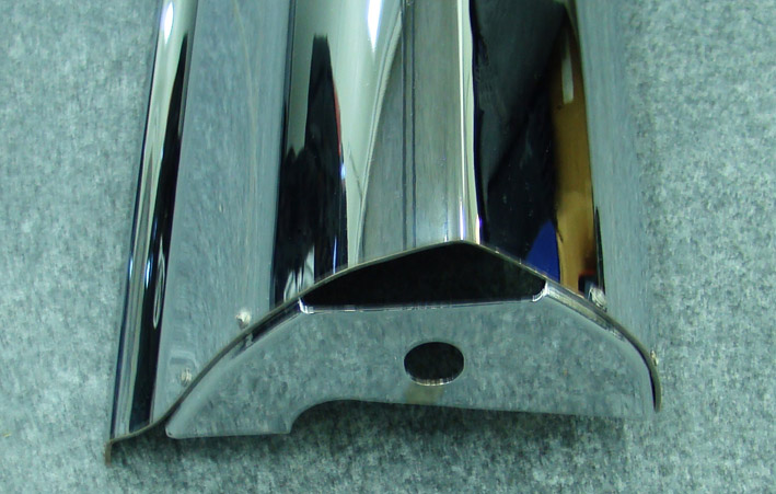 (3c - Mounted End Panel - Top View.jpg) (3c - Mounted End Panel - Top View.jpg)
Attachments
----------------
3a - Cutting Line at equal Distance.jpg (69KB - 779 downloads)
3b - Mounted End Panel - Rear View.jpg (143KB - 787 downloads)
3c - Mounted End Panel - Top View.jpg (113KB - 784 downloads)
|
|
| |
|
Expert
Posts: 1215
Location: SWITZERLAND | Soft Front Styling 2:
Here again: A soft styling is only visible when direct comparing with the original. This should just accentuate or hide some style elements being part of its original design. The parking lights of the 1959 Dodge I find just a little bit too much in the background (01). View from side, especially on pictures, the collars around the lamp body doesn’t show as they should (02). Not much better from top (03). By simply moving this unit to front, including the chrome bar, this would make this styling more exposed. Just remove the parking light assembly, put underneath washers or plates as distance, about 10 - 15mm at all according personal preference, the screws are long enough (04). Washers can be added and removed afterwards at any time. Then re-assemble the unit as well with the chrome bar mounted. My shortened chrome bars have anyway an additional bracket for fixing, thus before tightening it can be positioned, otherwise as well washers will be needed. The positioning of the chrome bars should be done carefully in order to keep the full harmony of the front. They should be aligned vertically (05) and horizontally according the bumpers inclination (06). After this small moving to front, the change can easy be seen at the mounted collars, or in direct comparison (07). Best effect is visible from inside (08) or exact from side position (09). This soft front styling injects to a 1959 Dodge a decent “horny” appearance! - SERGE -  N.B. The red rust-protecting paint behind the body (04) is from the former owner. He used to paint all with, even no rusting surfaces as shown here.
Edited by sermey 2012-07-08 7:35 AM
 (01 - Original Position.jpg) (01 - Original Position.jpg)
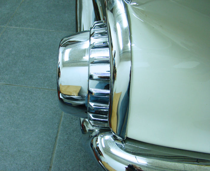 (02 - Before Moving - Side View.jpg) (02 - Before Moving - Side View.jpg)
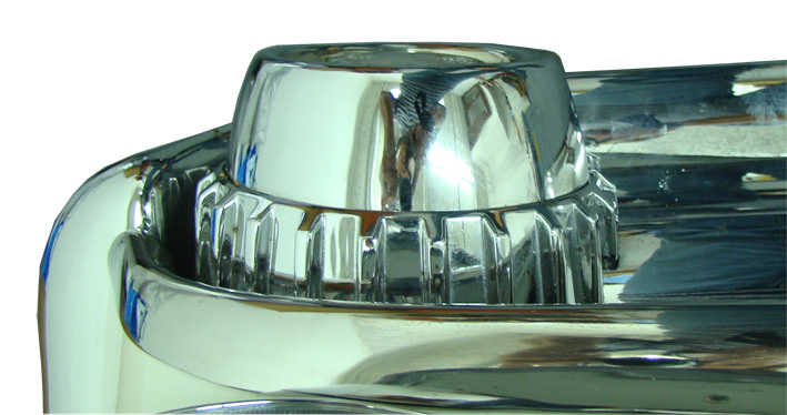 (03 - Before Moving - Top View.jpg) (03 - Before Moving - Top View.jpg)
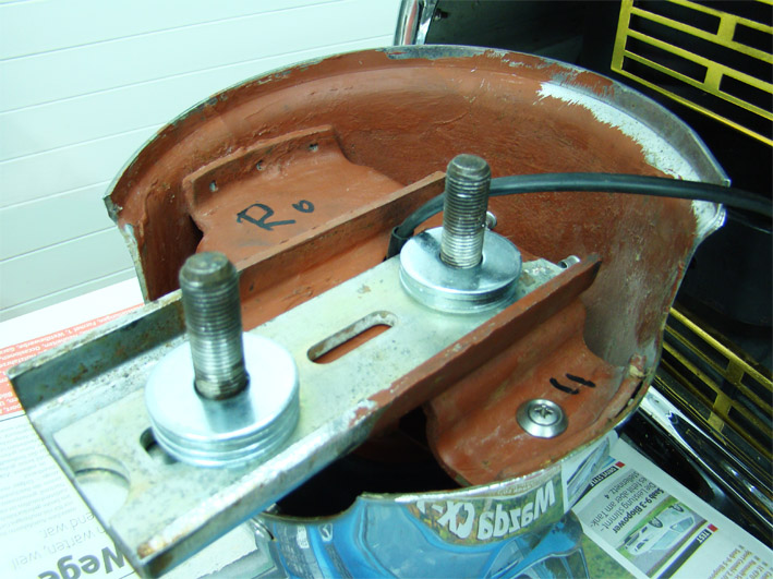 (04 - Distances-washer.jpg) (04 - Distances-washer.jpg)
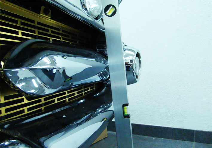 (05 - Vertical Alignment of the chrome bar.jpg) (05 - Vertical Alignment of the chrome bar.jpg)
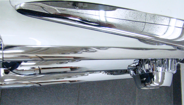 (06 - Horizontal Alignment of the chrome bar.jpg) (06 - Horizontal Alignment of the chrome bar.jpg)
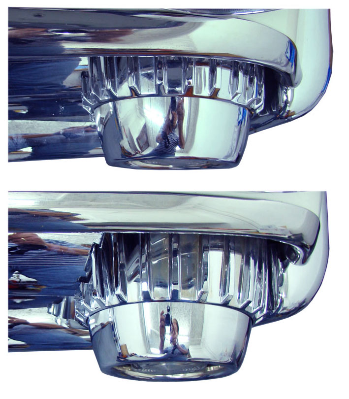 (07 - Comparison Before - After.jpg) (07 - Comparison Before - After.jpg)
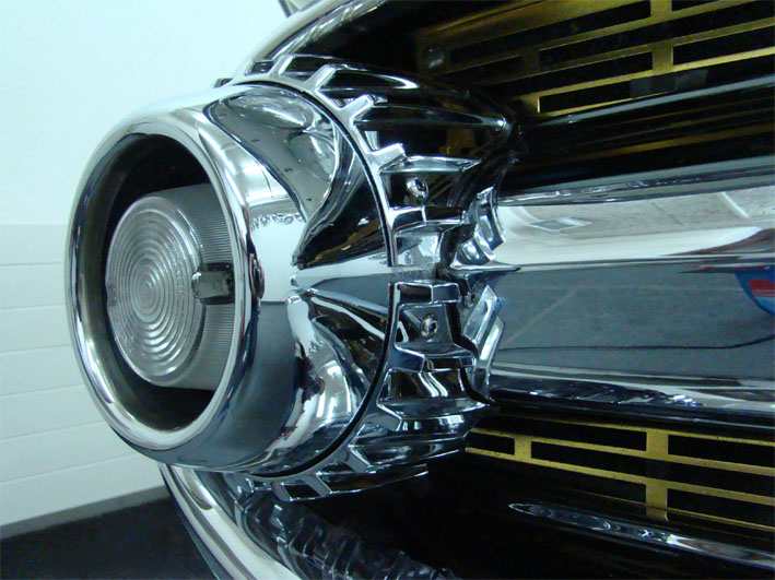 (08 - Moved - Right View.jpg) (08 - Moved - Right View.jpg)
 (09 - Moved - Side View.jpg) (09 - Moved - Side View.jpg)
Attachments
----------------
01 - Original Position.jpg (75KB - 742 downloads)
02 - Before Moving - Side View.jpg (97KB - 765 downloads)
03 - Before Moving - Top View.jpg (111KB - 772 downloads)
04 - Distances-washer.jpg (148KB - 784 downloads)
05 - Vertical Alignment of the chrome bar.jpg (129KB - 761 downloads)
06 - Horizontal Alignment of the chrome bar.jpg (113KB - 763 downloads)
07 - Comparison Before - After.jpg (146KB - 779 downloads)
08 - Moved - Right View.jpg (124KB - 775 downloads)
09 - Moved - Side View.jpg (115KB - 794 downloads)
|
|
| |
|
Expert
Posts: 1215
Location: SWITZERLAND | Head Lamp Assembly: The head lamps on my 1959 Dodge are un-centered (01), the glass-ring of one lamp is even nearly touching the head lamp bezel (02). There is no way provided to center them, they are factory “adjusted by design-engineering“. Here I show how I fixed it on the right head lamp. Same proceeding to apply for the other head lamps.
As all parts, including the beamer lining, are related to the main housing, no post-readjustment of the beamer will be needed when centered. The main unit has just to be moved toward the center position (03). To get the single head lamp unit adjustable the three fixing holes have to be enlarged to 6mm dia, or grinded to enable the needed shift. For the illustrated case here, this was not sufficient. Because the border of the main housing prevented to extend the fixing wholes as needed, this had to be done on the car-body side. I inserted riveting nuts M5 according the displacement. The aperture for the lamp unit on the car-body had as well to be grinded accordingly (04). I cut all M5 threads in the body, for easy inserting the stainless Alen screw M5 inside the assembly (05). Then I used the opportunity to give the glass-ring a soft polish (06).
Fix the lamp unit just to remain still movable. The glass-ring, as well the head lamp bezel, now have to be pre-fixed as reference for centering. When centered "by eye", remove again the head lamp bezel to have access to the fixing screws M5. With the final tightening and the re-mounted head lamp bezel the proceeding for this lamp is terminated (07). Of course, the head lamp bezel has always to be in the correct, aligned position to the fender.
Now the head lamp assembly is finally where it should be (08). -- SERGE – N.B. Depending on the front-angle when taking near pictures, the lamps seems somewhat uncentered.
Edited by sermey 2012-07-17 3:17 AM
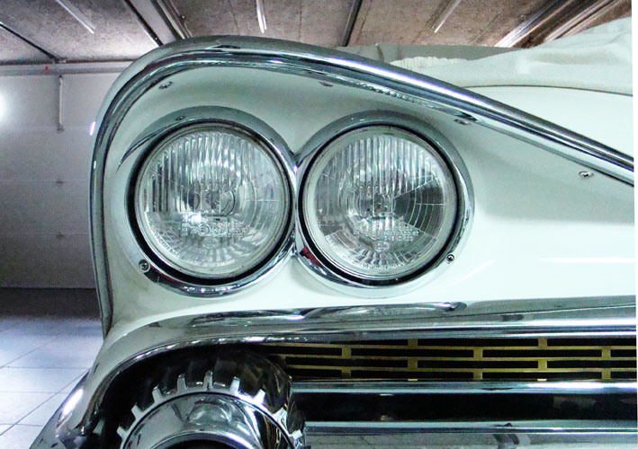 (01 - Uncentered head lamp assembly.jpg) (01 - Uncentered head lamp assembly.jpg)
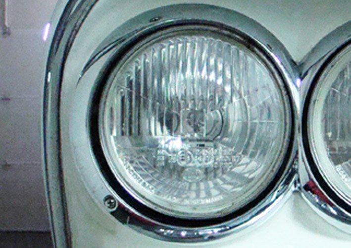 (02 - Uncentered head lamp zoomed.jpg) (02 - Uncentered head lamp zoomed.jpg)
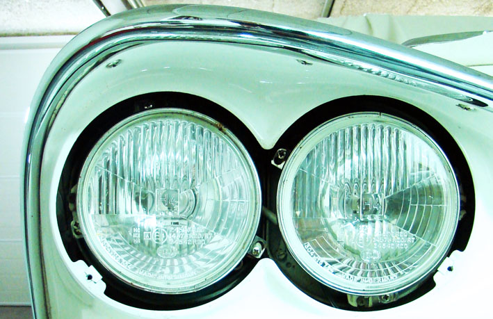 (03 - Uncentered removed head ligth bezel.jpg) (03 - Uncentered removed head ligth bezel.jpg)
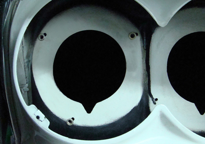 (04 - Moved riveting nuts - grinded aperture.jpg) (04 - Moved riveting nuts - grinded aperture.jpg)
 (05 - Easy inserting stainless Alen screw M5.jpg) (05 - Easy inserting stainless Alen screw M5.jpg)
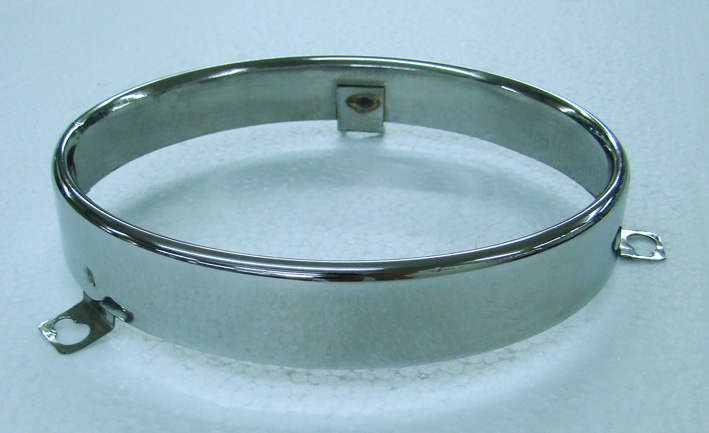 (06 - Head Lamp Ring polished.jpg) (06 - Head Lamp Ring polished.jpg)
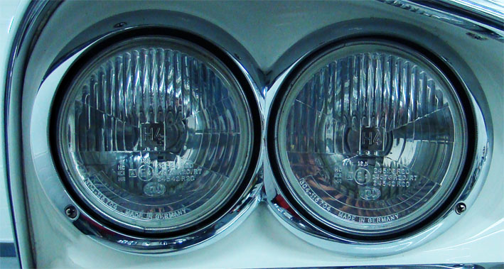 (07 - Centered Head Lamp Assembly zoomed.jpg) (07 - Centered Head Lamp Assembly zoomed.jpg)
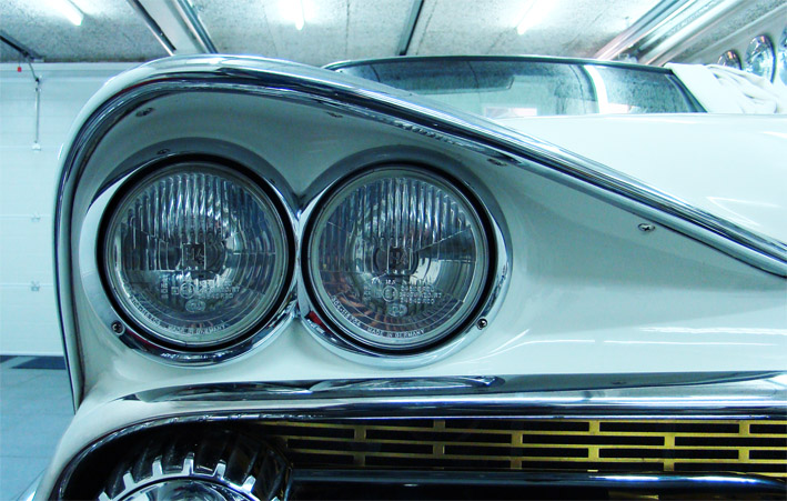 (08 - Centered Head Lamp Assembly.jpg) (08 - Centered Head Lamp Assembly.jpg)
Attachments
----------------
01 - Uncentered head lamp assembly.jpg (129KB - 768 downloads)
02 - Uncentered head lamp zoomed.jpg (129KB - 741 downloads)
03 - Uncentered removed head ligth bezel.jpg (126KB - 756 downloads)
04 - Moved riveting nuts - grinded aperture.jpg (129KB - 768 downloads)
05 - Easy inserting stainless Alen screw M5.jpg (94KB - 781 downloads)
06 - Head Lamp Ring polished.jpg (106KB - 755 downloads)
07 - Centered Head Lamp Assembly zoomed.jpg (114KB - 784 downloads)
08 - Centered Head Lamp Assembly.jpg (144KB - 747 downloads)
|
|
| |
|
Expert
Posts: 1215
Location: SWITZERLAND | Front Seats: The seat and the backrest cannot be adjusted. They have a fixed angle, as it was on all former American cars I owned. I found always the backrest a little bit too steep and uncomfortable (1). Thus, the first modification I used to do was to increase the angle between seat and backrest.
First remove backseat for easier handling. On the swivel seat, just rasp on each side near the both hinges, where the backrest is stopped, about 4.5mm deep (2). In back position the seat should fit on both sides (3). The angle then will increase from about 97deg to 103deg (90 + 13) (4).
Now, simply by a minor “surgical operation”, sitting in the car feels more relaxing and comfortable (5). - SERGE -
To know: The 6-way seat adjuster tilts the entire seat.
Edited by sermey 2012-07-23 2:26 PM
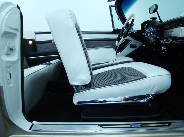 (1 - Front backseat before modification.jpg) (1 - Front backseat before modification.jpg)
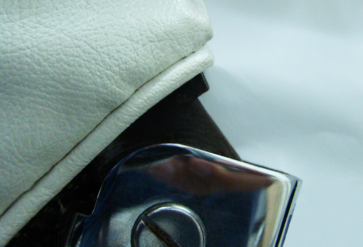 (2 - Front backseat rasped 4.5mm.jpg) (2 - Front backseat rasped 4.5mm.jpg)
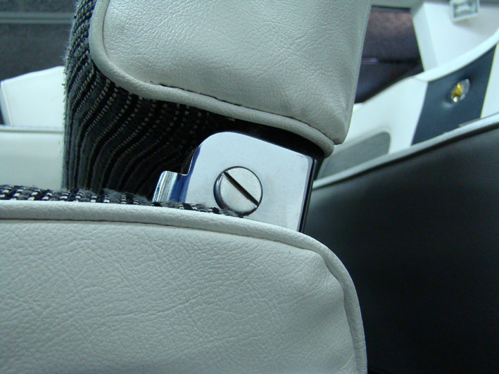 (3 - Front backseat in new position .jpg) (3 - Front backseat in new position .jpg)
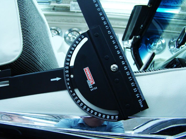 (4 - Final backseat angle 103deg.jpg) (4 - Final backseat angle 103deg.jpg)
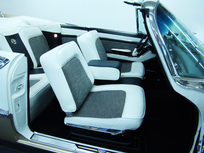 (5 - Both front backseats modified.jpg) (5 - Both front backseats modified.jpg)
Attachments
----------------
1 - Front backseat before modification.jpg (121KB - 745 downloads)
2 - Front backseat rasped 4.5mm.jpg (93KB - 761 downloads)
3 - Front backseat in new position .jpg (92KB - 757 downloads)
4 - Final backseat angle 103deg.jpg (127KB - 755 downloads)
5 - Both front backseats modified.jpg (134KB - 742 downloads)
|
|
| |
|
Expert
Posts: 1215
Location: SWITZERLAND | Black Painted Items 2: The black color spray I used for my items (see: http://www.forwardlook.net/forums/forums/thread-view.asp?tid=23691&...), my reserve has now exhaust and couldn’t get anymore. This was the best black spray I ever used. It needed many contacts with manufacturers and suppliers to find an equivalent. And now I have found the identical one, from another supplier, in a new wrapping. It has the same fast-drying solvent, as well exactly the same satin-matt tint. All my comparative tests showed identical results.
Here how they call it newly (marketing!): Rust Stop 4 in 1, Rust protecting paint, deep black, satin mat, RAL9005, and the products description, as printed:
Active rust protection by effective 4-in-1 high-solid coating system:
1. Primer. 2. Rust protection. 3. Colour. 4. Sealing. Fast-drying and high coverage. Excellent adhesion on nearly all surfaces, even directly on rust. Liquid corrosion inhibitor. Brand: Dupli-Color (868320). In Switzerland available in LANDI (03487).
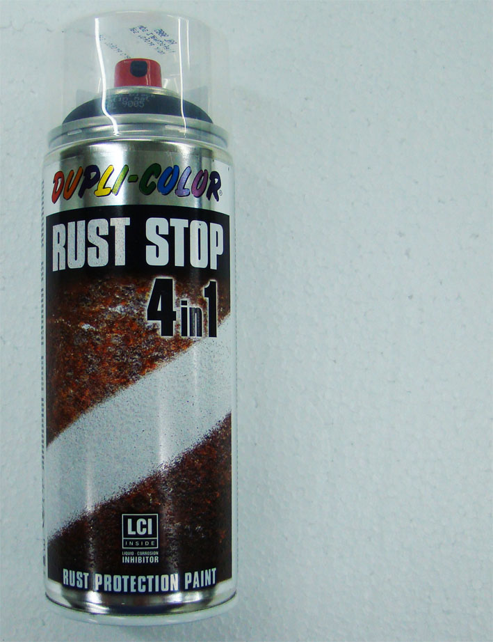 (New Black Spray Satin.jpg) (New Black Spray Satin.jpg)
Attachments
----------------
New Black Spray Satin.jpg (130KB - 758 downloads)
|
|
| |
|
Expert
Posts: 1215
Location: SWITZERLAND | Dual Rear Antenna Connection: At the end of the fifties in cars mostly radios for long waves (LF: 148.5kHz – 283.5kHz, 2000m - 1058m) and medium waves (MF: 520kHz – 1620kHz, 576m -185m ), with a bandwidth of 9kHz have been usual. For these radios, the option of dual rear antennas have been offered (1). Later, with radios for very short waves (VHF: 1m – 10m, UHF: 10cm – 1m), the dual rear antennas disappeared, due to interference and as result fading. On FWL-cars the dual rear antennas have a distance of 154.5cm (to relate with the RF wave length). They are parallel-connected with a coupler. The original has wrapped antenna cable (2). The repro needs a plugged cable extension (3). The so coupled dual antennas then will work without problems when connected to an original MF-radio. For best reception, this radio should be optimized in sensitivity by adjusting the capacitor trimmer near the antenna input (4) (5).
To a modern radio only one of these antennas should be connected, the second antenna, as stated, to the original MF- radio, or when removed or not working, just left unconnected.
My car has two radio receivers: the original radio type 857, (MF range “5 – 16”) located in the center of the dashboard (6), the loudspeaker as well on top center dashboard (*). The other multi-band stereo receiver with musicassette player and remote controle is hidden in the glove box. (7), the 6 loudspeakers are on both front bottom sides and on the rear.
Accordingly there are two separate antenna cables from the dual antennas, both along the right side under the sill plate to the radios. The rear left antenna leads to the original radio, the line here is longer and less loss-sensitive at lower RF-signals, the rear right antenna goes to the modern radio needing a shorter cable, with low capacity as used today.
Now, both radios work independently, even simultaneously, without any interference and fading (8). – SERGE –
(*) Details about the radio: http://www.forwardlook.net/forums/forums/thread-view.asp?tid=23691&...
Edited by sermey 2012-07-26 7:58 AM
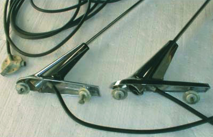 (1 - Set of Dual Rear Antennas NOS.jpg) (1 - Set of Dual Rear Antennas NOS.jpg)
 (2 - Original Dual Rear Antenna Coupler.jpg) (2 - Original Dual Rear Antenna Coupler.jpg)
 (3 - Repro Dual Rear Antenna Coupler.jpg) (3 - Repro Dual Rear Antenna Coupler.jpg)
 (4 - Capacitor Trimmer - Inside View.jpg) (4 - Capacitor Trimmer - Inside View.jpg)
 (5 - Hex Head Capacitor Trimmer - Outside View right side of radio.jpg) (5 - Hex Head Capacitor Trimmer - Outside View right side of radio.jpg)
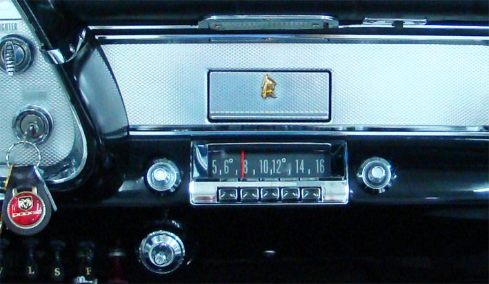 (6 - Original 1959 DODGE Radio.jpg) (6 - Original 1959 DODGE Radio.jpg)
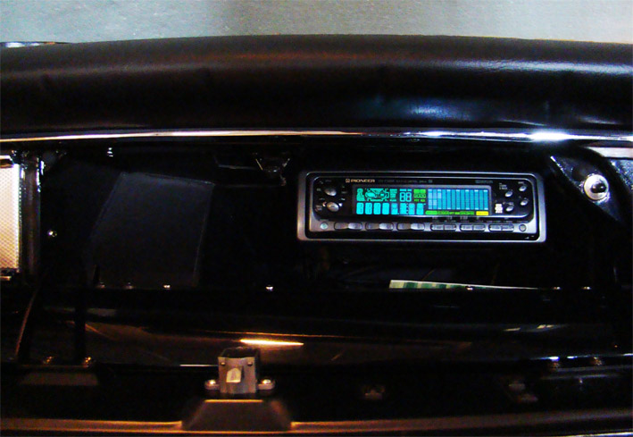 (7 - Multiband Musicassette Radio in Glovebox.jpg) (7 - Multiband Musicassette Radio in Glovebox.jpg)
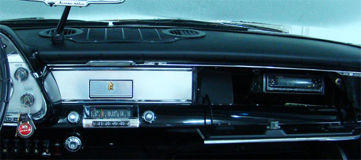 (8 - Two different Car-Radios.jpg) (8 - Two different Car-Radios.jpg)
Attachments
----------------
1 - Set of Dual Rear Antennas NOS.jpg (90KB - 740 downloads)
2 - Original Dual Rear Antenna Coupler.jpg (74KB - 777 downloads)
3 - Repro Dual Rear Antenna Coupler.jpg (59KB - 781 downloads)
4 - Capacitor Trimmer - Inside View.jpg (91KB - 749 downloads)
5 - Hex Head Capacitor Trimmer - Outside View right side of radio.jpg (80KB - 806 downloads)
6 - Original 1959 DODGE Radio.jpg (119KB - 774 downloads)
7 - Multiband Musicassette Radio in Glovebox.jpg (106KB - 760 downloads)
8 - Two different Car-Radios.jpg (92KB - 736 downloads)
|
|
| |
|
Board Moderator & Exner Expert 10K+
Posts: 13062
Location: Southern Sweden - Sturkö island | Again, thanks' Serge for good tips and tricks - I will copy the swivel seat backrest modification. You are totally right, the angle is too step OEM and full tilt does not give what a driver would like to have... |
|
| |
|
Elite Veteran
Posts: 1107
Location: Arvada, Colorado (NW Denver Metro Area) | Serge, I agree with Sven (Wizard) that is a great fix on the seats for a more comfortable sitting position with that modification to the stop area. I know you changed the rear seats too for a better angle of comfort but I will keep that angle as factory.
I also need to reverse my Chrome seat hinge screws, I have the slotted end inside and the clear rivet part out. I thought it looked better that way.
The seat pivot works fine but small details like that do count.
Edited by 1959 Belvedere Conv 2012-07-26 11:43 PM
|
|
| |
|
Expert
Posts: 1215
Location: SWITZERLAND | Front Seats 2: For those who want this modification to be reversible, here I did the seatback angle adjustable, to a fixed angle:
Cut on both sides of the lower seat hinge in the upper end a thread of M6 and insert a headless Allen screw of 10mm length (6).
Now the modified seatback angle (7) can be re-set to its original position (8) by compensating the rasped 4.5mm with the screw. Or you can adjust the angle to a minor amount to your best comfort (9). - SERGE - N.B. As I like my fixed setting, these pictures are real-view mounted for illustration on PS.
Edited by sermey 2012-07-27 3:10 AM
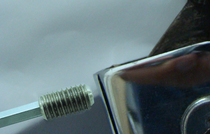 (6 - Headless Allen screw.jpg) (6 - Headless Allen screw.jpg)
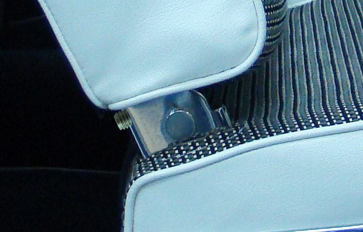 (7 - Max Seatback angle.jpg) (7 - Max Seatback angle.jpg)
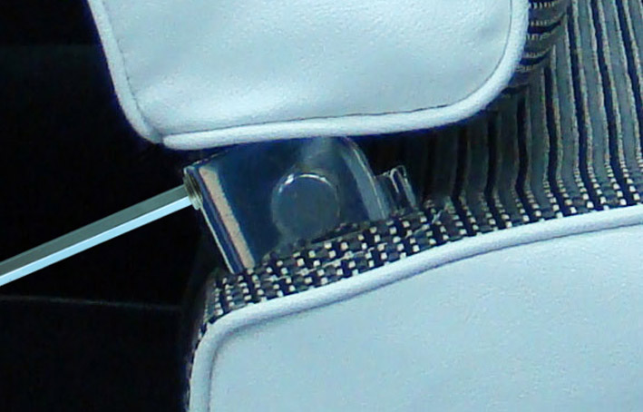 (8 - Reset Seatback angle.jpg) (8 - Reset Seatback angle.jpg)
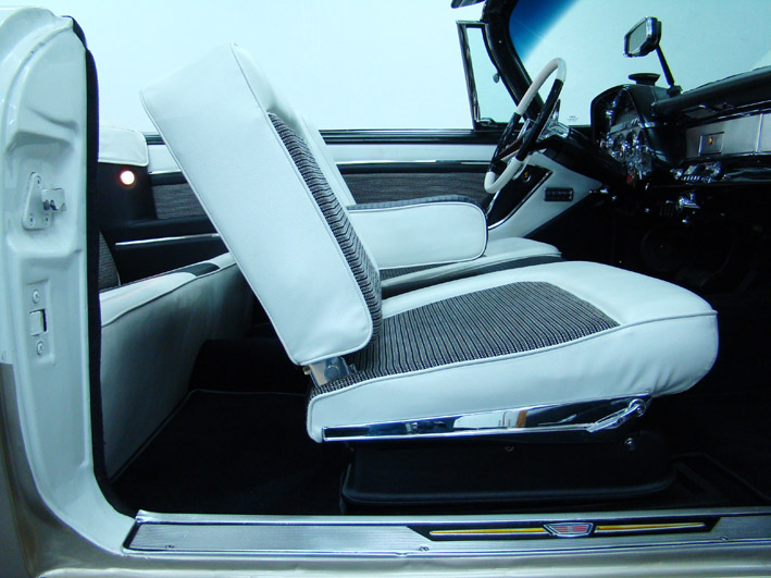 (9 - Visible Adjustable Backseat.jpg) (9 - Visible Adjustable Backseat.jpg)
Attachments
----------------
6 - Headless Allen screw.jpg (80KB - 754 downloads)
7 - Max Seatback angle.jpg (102KB - 700 downloads)
8 - Reset Seatback angle.jpg (90KB - 692 downloads)
9 - Visible Adjustable Backseat.jpg (123KB - 769 downloads)
|
|
| |
|
Expert
Posts: 2788
Location: USA - KY |
Amazing stuff, Serge!
Thank you for posting all of this...you should write a book!
Great photos...please keep them coming!
|
|
| |
|
Expert
Posts: 1215
Location: SWITZERLAND | FIN ME - 2012-08-02 4:57 PM Amazing stuff, Serge! Thank you for posting all of this...you should write a book! Great photos...please keep them coming! : ) Thanks for your kind comment, and to all the many people viewing this thread. Three hints to the photos: - 1. clean the item - 2. remove around all what not needed - 3. then at all if possible: NO flash to keep the deepness! - SERGE - |
|
| |
|
Expert
Posts: 1215
Location: SWITZERLAND | Fuel Alert Contact: In addition to: http://www.forwardlook.net/forums/forums/thread-view.asp?tid=23691&posts=173&start=41
I sacrificed various samples of micro-switches because their body was not resistant to fuel (01). Then I applied a simple way to get a cursor controlled contact, to switch ON a LED before the fuel tank is empty.
I used a copper plated board (PCB) as used in electronics. Then separated the copper plating in two sectors by grinding, one side A soldering to the ground and fixing, the other side B leading to the LED by a separate (black) wire. The hand-made cursor is soldered to the turning axis of the variable resistor (02). It needs an additional pad, very well sealed to the fuel (3). Inside, the wire is soldered (4). Just before the fuel tank is empty, the cursor grounds the LED to switch it ON. The other pad of the LED is connected to +5V (regulator), over a resistor of 180 – 470Ohm to fix the brightness. Now, when the LED goes on, I read the odometer and know exactly how far the remaining fuel will last, independent of the vague fuel gauge reading (05). For today cars nothing exceptional, but all the more on a fifties car. – SERGE -
N.B. The elegant solution is using a differetial OPAMP, no extra wires, but same variable resistor. Finally I was restoring a car, not again designing an electronic device.
Edited by sermey 2012-08-07 1:48 AM
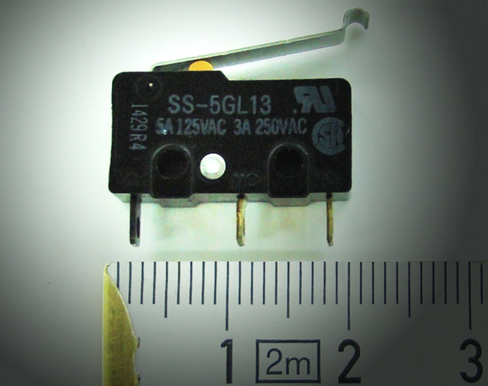 (01 - Micro-Switch.jpg) (01 - Micro-Switch.jpg)
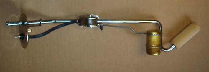 (02 - Mopar Fuel Sending Unit.jpg) (02 - Mopar Fuel Sending Unit.jpg)
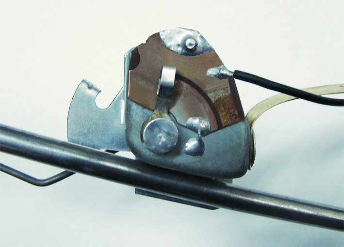 (03 - View PCB and Cursor on Resistor Unit.jpg) (03 - View PCB and Cursor on Resistor Unit.jpg)
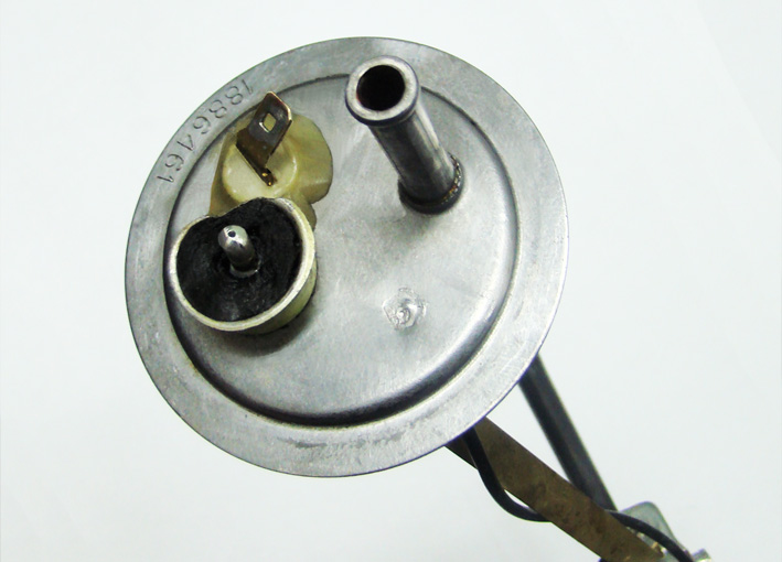 (04 - View Fuel Tank Unit Connections Side.jpg) (04 - View Fuel Tank Unit Connections Side.jpg)
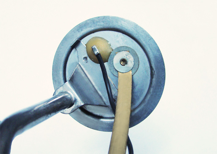 (05 - View Fuel Tank Unit Fuel Side .jpg) (05 - View Fuel Tank Unit Fuel Side .jpg)
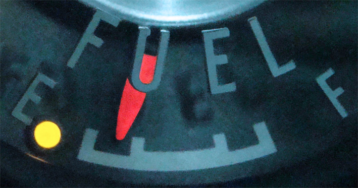 (06 - LED Alert at Empty Fuel Tank.jpg) (06 - LED Alert at Empty Fuel Tank.jpg)
Attachments
----------------
01 - Micro-Switch.jpg (100KB - 767 downloads)
02 - Mopar Fuel Sending Unit.jpg (67KB - 752 downloads)
03 - View PCB and Cursor on Resistor Unit.jpg (108KB - 769 downloads)
04 - View Fuel Tank Unit Connections Side.jpg (101KB - 762 downloads)
05 - View Fuel Tank Unit Fuel Side .jpg (99KB - 729 downloads)
06 - LED Alert at Empty Fuel Tank.jpg (130KB - 737 downloads)
|
|
| |
|
Expert
Posts: 1215
Location: SWITZERLAND | Wider tires: Modern wider tires transform a car visually to a more powerful vehicle. This is obvious when comparing two tire types next to each other on the similar FWL-Car: Original Dodge Diagonal Type, and replacement Radial Type (01). This and the much better stability on the street, mainly in curves and when braking, brought me to do this switch. First, shortly abstract considerations on dimensions:
_________________________________________________________________________________________
Diagonal Type 225/75/14”
DW = 355.6mm : [Diameter of Wheel (DW)14": 14 x 25.4mm= 355.6mm (1" = 25.4mm)]
HT = 168.75mm :[Height of the Tire (HT): 225mm x 75% = 168.75mm]
OD = 693.1mm : [Overall Diameter (OD): DW + (2 x HT) = 355.6mm + 337.5mm = 693.1mm (or 27.3")]
CC = 2176mm : [Circumference (CC): OD x 3.14 (pi) = 693.1mm x 3.14 = 2176.334 mm (or 85.7")]
Radial Type 235/70/15”
DW = 381mm : [Diameter of the Wheel (DW)15": DW = 15 x 25.4mm= 381mm]
HT = 164.5mm : [Height of the Tire (HT): HT = 235mm x 70% = 164.5mm]
OD = 710mm : [Overall Diameter (OD): OD = DW + (2 x HT) = 381mm + 329mm = 710mm (or 27.9")]
Overall Diameter measured OD = 708mm – I wonder how accurate (02).
CC = 2229.4mm : [Circumference (CC): CC = OD x 3.14 (pi) = 710mm x 3.14 = 2229.4 mm (or 87.7")]
____________________________________________________________________________________________
Differences and effects on car:
The Circumference CC (235/70/15") is 2.4% longer than the CC (225/70/14"). At same speedometer reading, now the car will run 2.4% faster. This difference is just tolerable without modifying the speedometer. Or otherwise: the speedometer will show 2.4% less at same speed. To calibrate the speedometer when needed, the return-spring in the speedometer should be lowered by lengthen, as calibrating mechanical watches.
The Overall Diameter OD (235/70/15") is 16.9mm bigger, thus the car will stay about this half amount higher. For the front this can be compensated by adjusting the torsion bars, and for the rear by setting down the high jackers.
The Wheel Distance with tires 8.00 x 14” is factory given by 60.9” (03) or 1546.8mm, on my car with the wider tires it is 1624mm, about 77mm more.
There is a noticeable difference in the Road Contact when measured: the Diagonal Type 125mm (04), and the Radial Type 175mm (05). This is 40% more! Highlighted the rear left tire on the street (06), or another front view (07).
Wider tires offer more security and power-feeling in one step. Just keep the original hubcaps on the car, and keep as well in reserve the original wheels. – SERGE –
P.S. (01) Partly Picture: Quentin Willson “Classic American Cars”
Edited by sermey 2012-08-07 9:37 AM
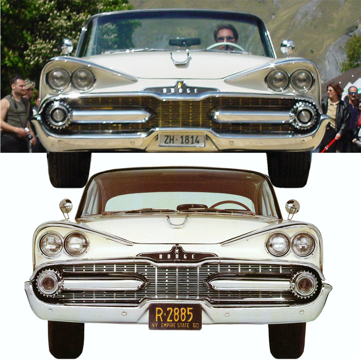 (01 - Comparison Front View.jpg) (01 - Comparison Front View.jpg)
 (02 - Measured Radial Overall Diameter 708mm.jpg) (02 - Measured Radial Overall Diameter 708mm.jpg)
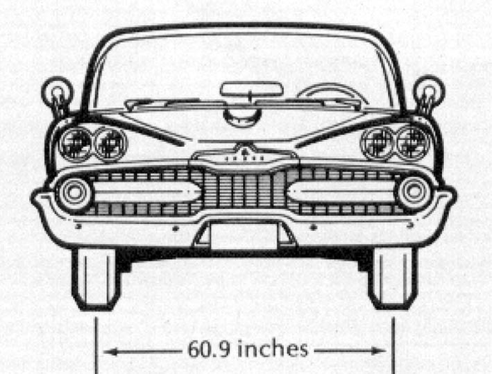 (03 - 1959 Dodge Promoted Tire 800 x 14in.jpg) (03 - 1959 Dodge Promoted Tire 800 x 14in.jpg)
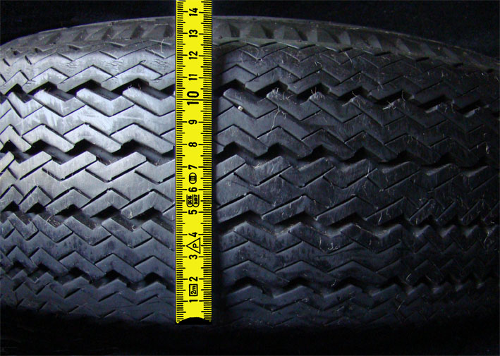 (04 - Measured Diagonal Road Contact 125mm.jpg) (04 - Measured Diagonal Road Contact 125mm.jpg)
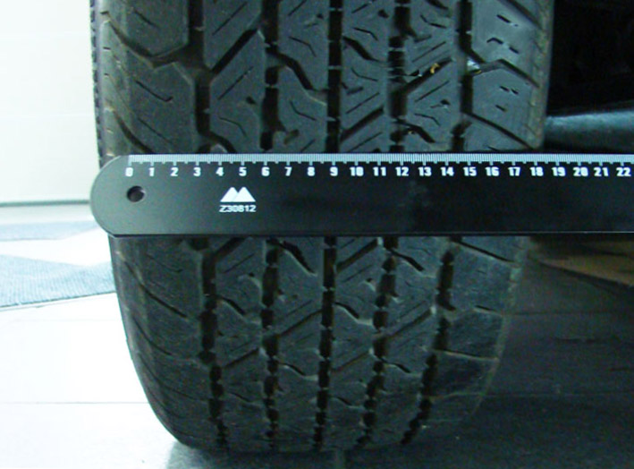 (05 - Measured Radial Road Contact 175mm.jpg) (05 - Measured Radial Road Contact 175mm.jpg)
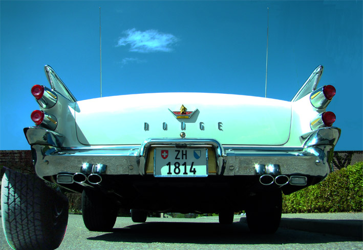 (06 - Rear View zoomed Left Radial Contact on Road.jpg) (06 - Rear View zoomed Left Radial Contact on Road.jpg)
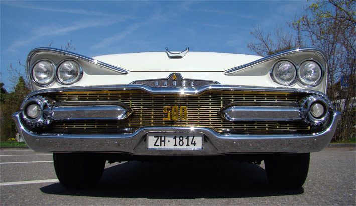 (07 - Front View Radial Contact on Road.jpg) (07 - Front View Radial Contact on Road.jpg)
Attachments
----------------
01 - Comparison Front View.jpg (160KB - 737 downloads)
02 - Measured Radial Overall Diameter 708mm.jpg (104KB - 727 downloads)
03 - 1959 Dodge Promoted Tire 800 x 14in.jpg (90KB - 768 downloads)
04 - Measured Diagonal Road Contact 125mm.jpg (130KB - 734 downloads)
05 - Measured Radial Road Contact 175mm.jpg (111KB - 747 downloads)
06 - Rear View zoomed Left Radial Contact on Road.jpg (114KB - 759 downloads)
07 - Front View Radial Contact on Road.jpg (118KB - 737 downloads)
|
|
| |
|

Veteran
Posts: 241
Location: Southern CA | Thanks for sharing all the great tips, I will apply many to my car (as soon as I get one). Your car is awesome! |
|
| |
|
Expert
Posts: 2598
Location: Upplands Väsby, Sweden | Hi sermey
Your are Good to ut better,
I dont like this, maby you can Do this better: Only one stop when you open the door
At fl Cars. I Will have two stop. Some times at parking you have not lots off space, and only can oppend
The door litle. |
|
| |
|
Expert
Posts: 1215
Location: SWITZERLAND | Leadfoot1000 - 2012-08-08 4:07 AM Thanks for sharing all the great tips, I will apply many to my car (as soon as I get one). Your car is awesome!
Thank you and as new member welcome on this site. What you see here is mostly “cold coffee”, because the restoration was completed about 15 years ago. At this time I had no digital camera. Now, not so easy to comment and particular to show “before – after”. Sometimes I must use pictures of other cars as reference. - SERGE -
Edited by sermey 2012-08-08 2:29 PM
|
|
| |
|
Expert
Posts: 1215
Location: SWITZERLAND | Wide tires: Supplement
Edited by sermey 2012-08-08 3:40 PM
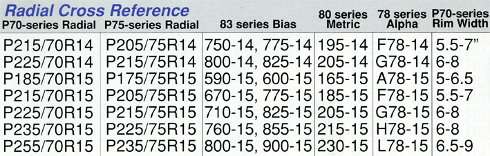 (Coker Tire Radial Cross Reference.jpg) (Coker Tire Radial Cross Reference.jpg)
Attachments
----------------
Coker Tire Radial Cross Reference.jpg (169KB - 840 downloads)
|
|
| |
|
Expert
Posts: 1215
Location: SWITZERLAND | Windsor59 - 2012-08-08 8:50 AM Hi sermey Only one stop when you open the door At fl Cars. I Will have two stop. . . .
A useful option that make sense. I will have a look at. - SERGE - |
|
| |
|
Expert
Posts: 1215
Location: SWITZERLAND | Filling Fine Scripts: For fine letters, standard paints will sometimes “over-layer” when filling. For this purpose, the thinnest paint I found was the Permanent Refill Ink (01), used for water resistant marker felt pens. It is very fast-drying and has a high coverage.
Apply with an ultra fine brush or needle (*), and when dried, remove the over-paint simply by rubbing with the finger or a school rubber. If too resistive use a fine cloth, moistened with solvent without pressing.
Now, the newly filled fine scripts have got a much higher contrast and thus become significantly better readable. – SERGE - 
(*) A felt pen is not suitable for a homogeneous coating on metal.
Edited by sermey 2012-08-14 8:30 PM
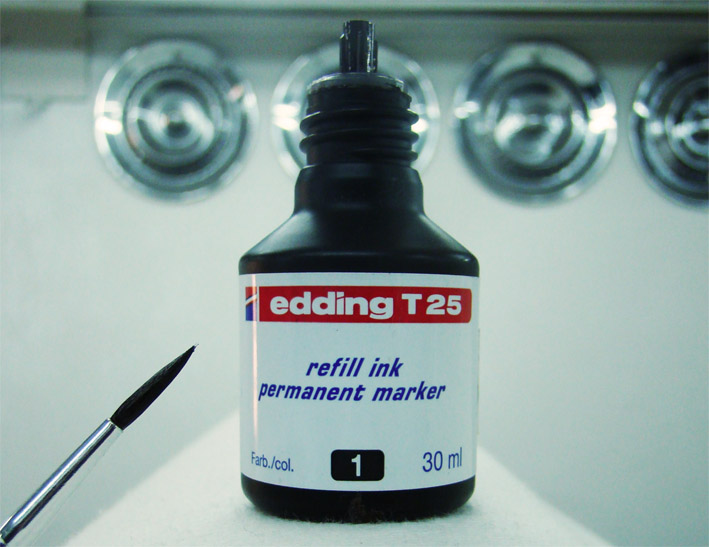 (01 - Refill Ink Permanent Marker.jpg) (01 - Refill Ink Permanent Marker.jpg)
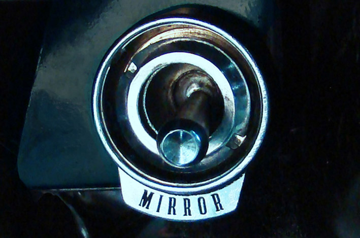 (02 - Filling fine script MIRROR.jpg) (02 - Filling fine script MIRROR.jpg)
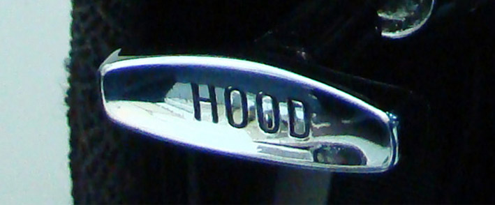 (03 - Filling fine script HOOD.jpg) (03 - Filling fine script HOOD.jpg)
Attachments
----------------
01 - Refill Ink Permanent Marker.jpg (97KB - 734 downloads)
02 - Filling fine script MIRROR.jpg (108KB - 726 downloads)
03 - Filling fine script HOOD.jpg (61KB - 754 downloads)
|
|
| |
|
Expert
Posts: 1215
Location: SWITZERLAND | Leaking Valve Covers: At the first glance it seemed to be an easy thing to mount the valve covers without any leaking . . . . . but finally I got it.
First all contact surfaces of the valve cover have to be properly mated all around. Often, around the bolt holes the cover is deformed due to a previous too strong tightening.
For a sure sealing, Silicon Gasket (as already presented earlier) is applied just on the inner edges of the valve cover (1). Remember: this is not glue for fixing and will not harden. It remains soft (20 shore) and allows an easy removal of the cover. Any other similar Silicon can be used, but it must be resistant to temperatures in the range of -40 to +180deg. Before tightening, when visible the gasket then can be pushed under the cover (2).
To avoid local high pressing and a deformation around the head of the bolt, special hold-down brackets are being used. These give two additional extended hold-down points (3). The big washer improves the local stability around the bolt holes, shorten virtually the bolt for the cap nut and hide the eccentric bore.
Polished stainless cap nuts (4) underline the overall harmonic style of the engine compartment (5). - SERGE -
Edited by sermey 2012-09-01 3:03 PM
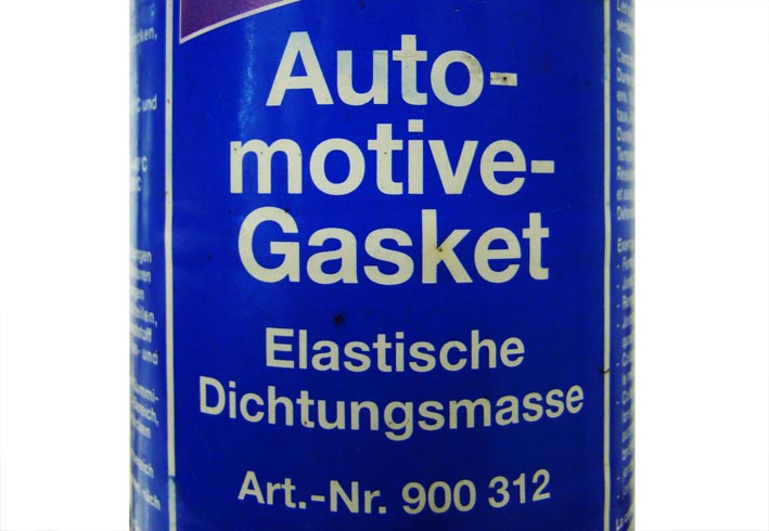 (1 - Automotive Gasket.jpg) (1 - Automotive Gasket.jpg)
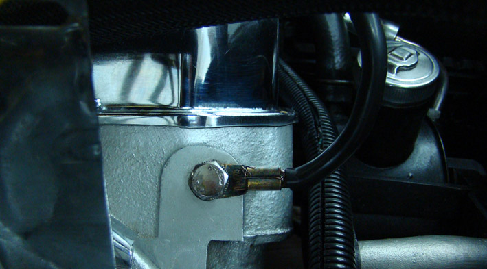 (2 - Aligned Valve Cover.jpg) (2 - Aligned Valve Cover.jpg)
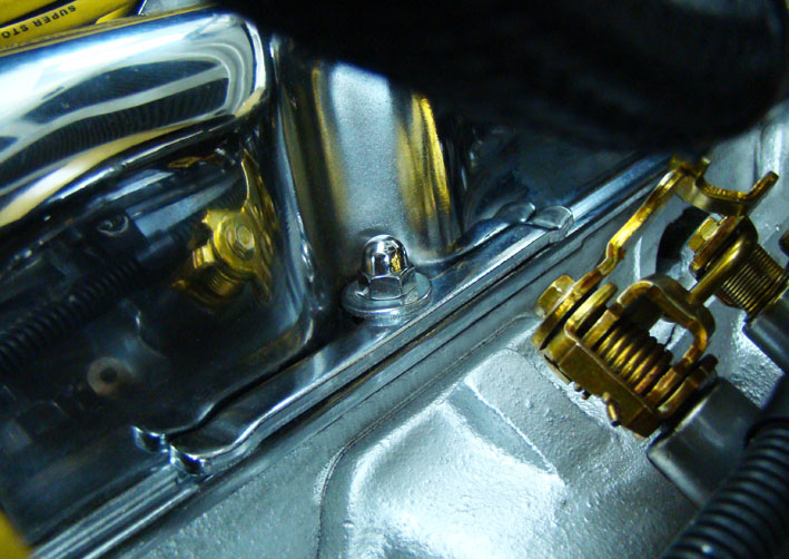 (3 - Valve Cover Hold-Down Bracket.jpg) (3 - Valve Cover Hold-Down Bracket.jpg)
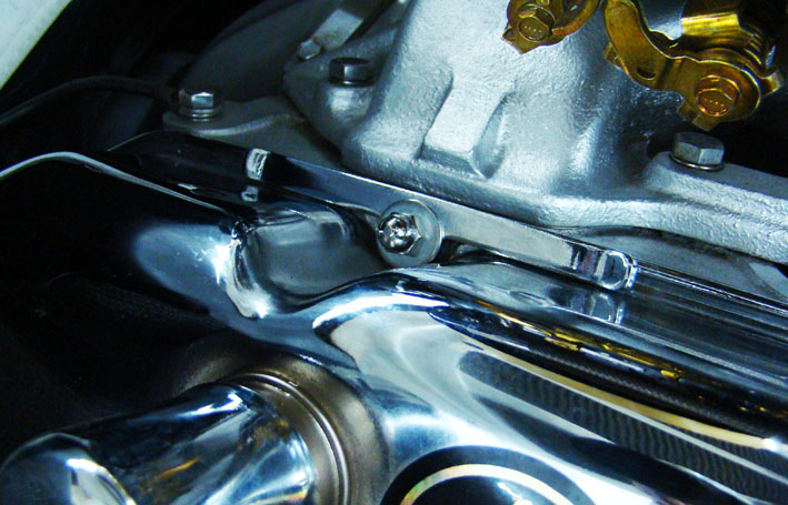 (4 - Fixed Valve Cover.jpg) (4 - Fixed Valve Cover.jpg)
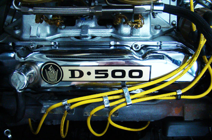 (5 - Valve Cover Top View.jpg) (5 - Valve Cover Top View.jpg)
Attachments
----------------
1 - Automotive Gasket.jpg (72KB - 803 downloads)
2 - Aligned Valve Cover.jpg (93KB - 774 downloads)
3 - Valve Cover Hold-Down Bracket.jpg (120KB - 725 downloads)
4 - Fixed Valve Cover.jpg (117KB - 724 downloads)
5 - Valve Cover Top View.jpg (136KB - 741 downloads)
|
|
| |
|
Expert
Posts: 1215
Location: SWITZERLAND | Carpets and Floor Mats 1: With my 1959 Dodge Convertible I got white Knight Rubber Mats I never saw elsewhere. I found these exceptional and thus present them here. The Side Emblem ot the front mat seems to be equal to the Center Emblem. Since restored, I used other Carpets and Floor Mats in my car, and will thread them in a next part to come. - SERGE -
Edited by sermey 2012-09-02 4:27 AM
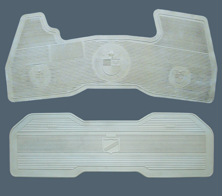 (01 - 1959 Knight Rubber Mats Front - Rear.jpg) (01 - 1959 Knight Rubber Mats Front - Rear.jpg)
 (02 - Knight Mat - Front Center Emblem.jpg) (02 - Knight Mat - Front Center Emblem.jpg)
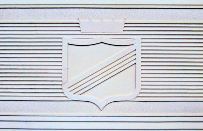 (03 - Knight Mat - Rear Center Emblem.jpg) (03 - Knight Mat - Rear Center Emblem.jpg)
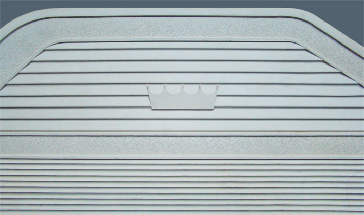 (04 - Knight Mat - Rear Side Emblem.jpg) (04 - Knight Mat - Rear Side Emblem.jpg)
Attachments
----------------
01 - 1959 Knight Rubber Mats Front - Rear.jpg (150KB - 835 downloads)
02 - Knight Mat - Front Center Emblem.jpg (122KB - 710 downloads)
03 - Knight Mat - Rear Center Emblem.jpg (94KB - 714 downloads)
04 - Knight Mat - Rear Side Emblem.jpg (99KB - 741 downloads)
|
|
| |
|
Expert
Posts: 1215
Location: SWITZERLAND | Carpets and Floor Mats 2: On the market a wide range of said "Original Floor Mats" are offered. There are very nice ones and available at a reasonable price. Others, described as “original” size doesn’t fit at all.
I set my personal standards on quality, material, color and finish, mainly based on practical considerations. Furthermore, on a Convertible some specs on carpets have higher weighting, being more exposed than on a Sedan.
Here my arguments:
1. The quality. There are two basic carpet versions being used: the "loop pile" and the "cut pile" (05). Practical arguments brought me to use exclusively "cut pile" carpet.(06):
Cleaning a carpet from any dirt, the "loop pile" prevents to remove it, the dirt will even enter more in the carpet. Furthermore, hanging on a loop, the carpet may be damaged all along a line.
Other the "cut pile": when brushing, the slanted pile supports to take out the dirt easily. It is invisible, when added two parts together, or when inserted a round stamped sample in damaged spots.
Walking on a good quality cut pile floor is noticeable much more comfortable, and it has a better absorbance of sound and noise.
2. The material. In a car, exposed to humidity and oil, a full synthetic material is a must. It doesn't rot, thus offer a longer lifetime, and is much more resistive to aggressive cleanser.
3. The color. It should match to the interior of the car, preferably unicolored not visually interfering to other items. Unicolor generally looks more precious, is calmative, but as well more delicate when not clean.
4. The finish: Solid and wear resistant base enabling to glue when needed, no under foam-coating, all around bordered to prevent fringing.
On my Convertible, at the time not finding floor insertions or original mats, all was custom made with loop pile carpets, black synthetic, solid tissue base and vinyl-bordered all around (07) (08).
Instead of bordering, on straight edging a plastic profiles as used to fix papers can be applied as protection (09). The same profile I used inside of my door sills (see: http://www.forwardlook.net/forums/forums/thread-view.asp?tid=23691&posts=184&start=13). If needed for attaching, rubber or plastic items can be inserted as shown (10).
(will be continued)
 (05 - Basics Loop Pile - Cut Pile.jpg) (05 - Basics Loop Pile - Cut Pile.jpg)
 (06 - Carpets Loop Pile - Cut Pile.jpg) (06 - Carpets Loop Pile - Cut Pile.jpg)
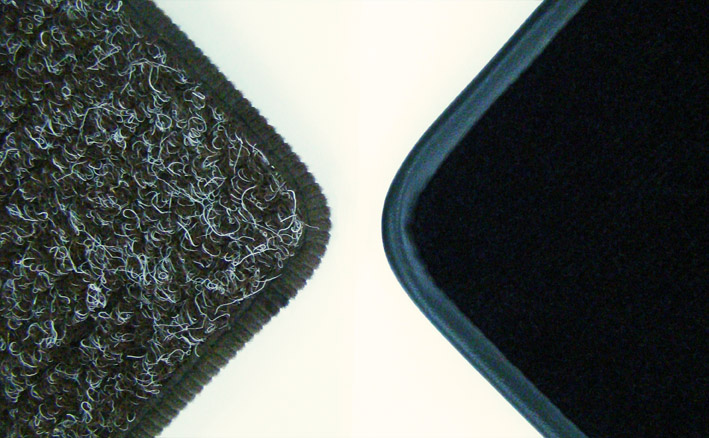 (07 - Carpets Loop Pile - Cut Pile Upper Side bordered.jpg) (07 - Carpets Loop Pile - Cut Pile Upper Side bordered.jpg)
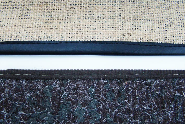 (08 - Carpets Loop Pile - Cut Pile Under Side bordered.jpg) (08 - Carpets Loop Pile - Cut Pile Under Side bordered.jpg)
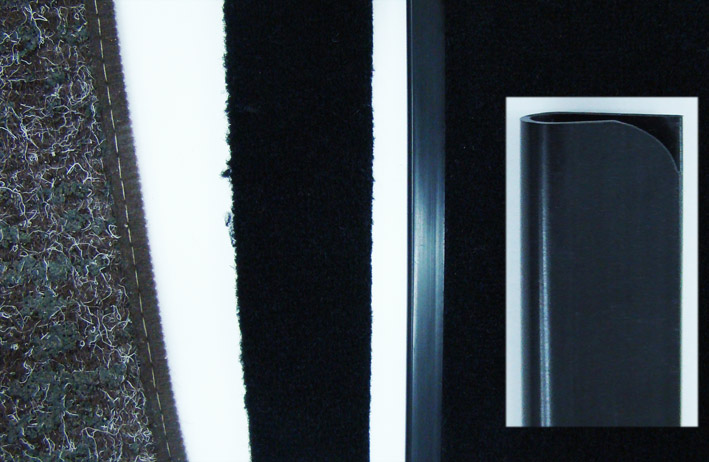 (09 - Alternative bordering with a Profile.jpg) (09 - Alternative bordering with a Profile.jpg)
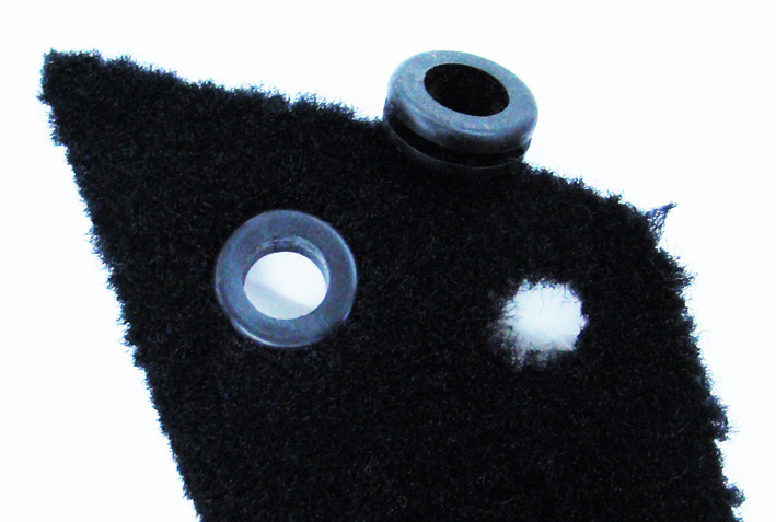 (10 - Rubber for attaching.jpg) (10 - Rubber for attaching.jpg)
Attachments
----------------
05 - Basics Loop Pile - Cut Pile.jpg (96KB - 734 downloads)
06 - Carpets Loop Pile - Cut Pile.jpg (154KB - 738 downloads)
07 - Carpets Loop Pile - Cut Pile Upper Side bordered.jpg (130KB - 758 downloads)
08 - Carpets Loop Pile - Cut Pile Under Side bordered.jpg (132KB - 739 downloads)
09 - Alternative bordering with a Profile.jpg (109KB - 751 downloads)
10 - Rubber for attaching.jpg (109KB - 750 downloads)
|
|
| |
|
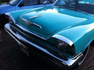
Expert
Posts: 1295
Location: Nasco , SWEDEN | This thread is really outstanding, just love to read an see what he´s up to! Sermey "The Magic Man" |
|
| |
|
Veteran
Posts: 241
Location: Southern CA | sermey - 2009-02-01 4:44 AM
15” Wheels and Tires: I always found, 14” Wheels on my Car are relatively too small and look poor in Proportion to the Body and its Wheelhouse. Must say, this was the Style at this time. The other Point, bigger and wider Tires have much better Adhesion on the Street, the 235/70/15 Radial Tires about +25% in Comparison to the Original 14” Diagonal ones. This improvement is necessarily needed for a full Advantage of Disk Brakes. Thus, I decided in favor of 15” Wheels and the corresponding WWW Tires, still keeping the Original 14” Wheel Set including the Spinner Hubcaps. In order to keep the Original Appearance, the Original HubCaps should fit to the 15” Rims. I bought 15” decorative stainless Rings, cut out the Border around, and soldered it inside the Wheel Cover. For a stronger Fixing on the rechromed Wheels I increased the Clamp Pression by putting a soft round PVC Profile under the Clamps. Now, the Hubcaps fit perfectly to the 15” Rims, their Edges are even protected from Curbstones due to the inner Position, and the Air Valve is perfectly centered as well. According my personal feeling, this Wheel Size gives the Car its settled Proportions. Another improvement of the Outfit, for the Drivers Security, and as an additional Benefit the Wheel Cover Edge Protection. (can see, my HubCaps are not perfect, but polished and with the sticked Black they look as)
Hi Sermey, I plan to get 235-70/15's for my car also. Can you please tell me what's the width of the white walls on your tires? Your choice of white walls provides the same look I'm trying to achieve. By the way, I bought a car a few weeks ago if you want to see it under Member's Rides title "My 57 New Yorker." Steve |
|
| |
|
Expert
Posts: 1215
Location: SWITZERLAND | Leadfoot1000 - 2012-09-08 7:01 AM sermey - 2009-02-01 4:44 AM . . . . what's the width of the white walls on your tires? Steve Measured on the car: 70.5mm = 2.775" According the Manufacturer Coker Tire: Radial P235/70R15, WW 2n3/4 (see attached Specs 2012) - SERGE -
Edited by sermey 2012-09-08 7:25 AM
 (1959 DODGE Custom Royal Lancer Convertible 2012.jpg) (1959 DODGE Custom Royal Lancer Convertible 2012.jpg)Attachments ---------------- 1959 DODGE Custom Royal Lancer Convertible 2012.jpg (231KB - 731 downloads) 1959 DODGE Custom Royal Lancer Convertible 2012.pdf (148KB - 918 downloads) |
|
| |
|
Expert
Posts: 1215
Location: SWITZERLAND | Fan Shroud: My car didn’t had a Fan Shroud (01). On a car meeting I purchased a Chrome Metal Fan Shroud, thinking this would give the engine compartment a more valuated look, will prevent parts or screws falling on the propeller when working at idling, and as protection from casually touch inside. (old Pic 02). So far so good.
In hot summer, at longer stops and idling I encountered critical heating situations, the engine room got quite hot. I was reflecting: without a shroud, the fan blows not only axial, but as well partially radial as a centrifugal fan. My Metal Shroud, covering only 65% of the propeller, now caused in idle more air to be centrifuged downward instead towards the engine. -> Just check it!
I took a high temperature Heat Protective Mat (03), put this over a panel to seal airtight underneath the fan and front (04). As result, the heating was noticeable reduced. Then I purchased two Chrome Metal Shrouds, the longest available (170mm), one for the upper, the other one for the lower side of the fan. They had to be exactly marked for a partly cut-out to fit all around (05). Needed cut-outs for: the water hose (06), the generator belt (07), the steering pump, the transmission oil lines (08), and a bending on the fuel pump side (09). All these cuts were previously simulated with a cardboard sample. Then the prepared two halves (to see lower Shroud) (10) (11) could be mounted very easy, without disassembling anything, and fixed with long bolts through the radiator.
The distance of the shroud to the propeller, here should be taken in consideration the movement of the engine on bad streets. The short Metal Shroud was initially mounted too near, as signs of contacts can be seen on the comparison (12).
Now this Chrome Metal Shroud makes multiple sense: protection, outfit and an improved cooling at longer stop (13). - SERGE - Comment: If you find a standard shroud fitting the radiator you will save some handiwork, but will have to disassemble some items!
Edited by sermey 2012-09-08 12:35 PM
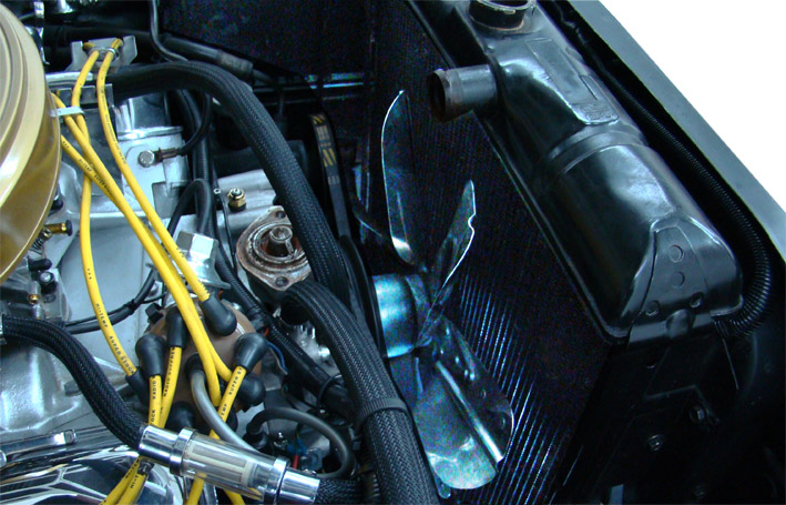 (01 - Unprotected Fan - Water Hose Removed.jpg) (01 - Unprotected Fan - Water Hose Removed.jpg)
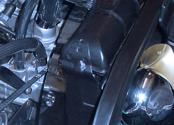 (02 - Short Metal Shroud Mounted.jpg) (02 - Short Metal Shroud Mounted.jpg)
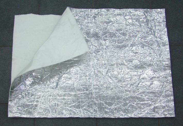 (03 - Heat Protective Mat.jpg) (03 - Heat Protective Mat.jpg)
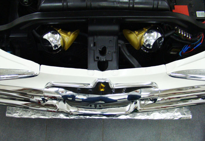 (04 - Protective Heat Protective Mat under Fan.jpg) (04 - Protective Heat Protective Mat under Fan.jpg)
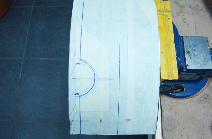 (05 - Metal Shroud Ready for Cut.jpg) (05 - Metal Shroud Ready for Cut.jpg)
 (06 - Cut-Out for Water Hose.jpg) (06 - Cut-Out for Water Hose.jpg)
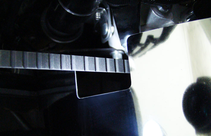 (07 - Cut-Out for Generator Belt.jpg) (07 - Cut-Out for Generator Belt.jpg)
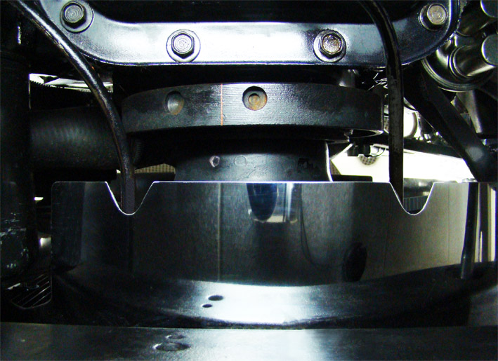 (08 - Bottom View Trans Line.jpg) (08 - Bottom View Trans Line.jpg)
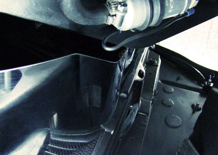 (09 - Bent for under Trans Lines.jpg) (09 - Bent for under Trans Lines.jpg)
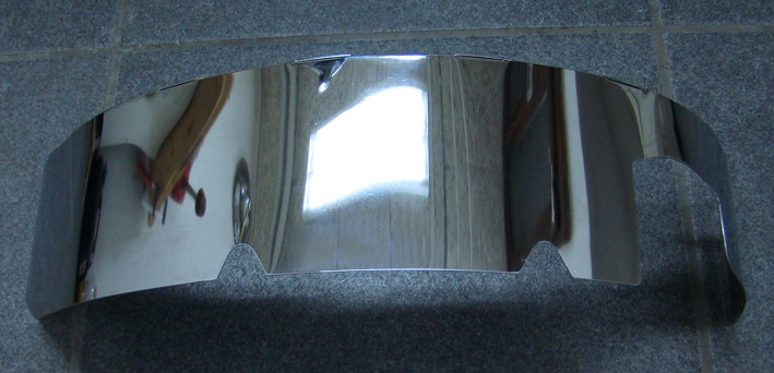 (10 - Lower Metal Shroud Cut - Outside View.jpg) (10 - Lower Metal Shroud Cut - Outside View.jpg)
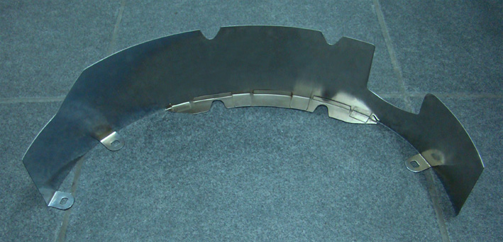 (11 - Lower Metal Shroud Cut - Inside View.jpg) (11 - Lower Metal Shroud Cut - Inside View.jpg)
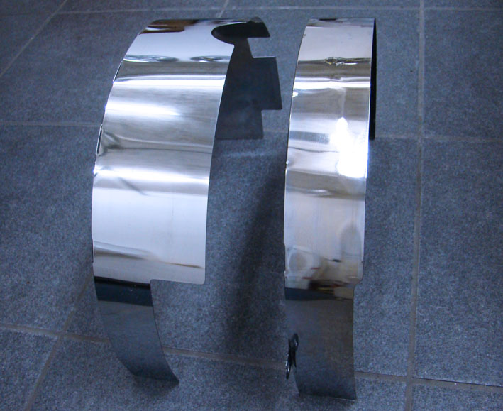 (12 - Short and Long Metal Shroud - Cut.jpg) (12 - Short and Long Metal Shroud - Cut.jpg)
 (13 - Chrome Metal Shroud 170mm - Top View.jpg) (13 - Chrome Metal Shroud 170mm - Top View.jpg)
Attachments
----------------
01 - Unprotected Fan - Water Hose Removed.jpg (153KB - 717 downloads)
02 - Short Metal Shroud Mounted.jpg (137KB - 722 downloads)
03 - Heat Protective Mat.jpg (116KB - 727 downloads)
04 - Protective Heat Protective Mat under Fan.jpg (100KB - 759 downloads)
05 - Metal Shroud Ready for Cut.jpg (94KB - 698 downloads)
06 - Cut-Out for Water Hose.jpg (112KB - 724 downloads)
07 - Cut-Out for Generator Belt.jpg (82KB - 726 downloads)
08 - Bottom View Trans Line.jpg (138KB - 729 downloads)
09 - Bent for under Trans Lines.jpg (114KB - 738 downloads)
10 - Lower Metal Shroud Cut - Outside View.jpg (108KB - 758 downloads)
11 - Lower Metal Shroud Cut - Inside View.jpg (114KB - 721 downloads)
12 - Short and Long Metal Shroud - Cut.jpg (101KB - 728 downloads)
13 - Chrome Metal Shroud 170mm - Top View.jpg (133KB - 723 downloads)
|
|
| |
|
Expert
Posts: 1215
Location: SWITZERLAND | Trunk Edge: The lower trunk edge is most exposed to damage when loading items not carefully. The paint is most badly affected. In addition, this edge is even not exactly straight.
A profile in plastic or rubber, preferably in the cars color, could eliminate this situation. I found a plastic channel used in electric installations, in white as the car (1). The cover fits to the trunk edge as required (2). The trunk seal keep it in the right position (3) ( ! the carpet is black and ends up with the profile). Some rubber profiles or a small slotted hose would work as well.
Now, the trunk edge is protected, straight, no color damages anymore, all as it should always be (4). – SERGE -
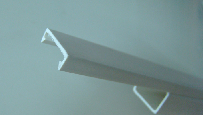 (1 - White Profile.jpg) (1 - White Profile.jpg)
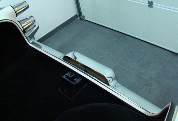 (2 - Applied White Protective Profile.jpg) (2 - Applied White Protective Profile.jpg)
 (3 - Protective Profile fixed behind Trunk Seal.jpg) (3 - Protective Profile fixed behind Trunk Seal.jpg)
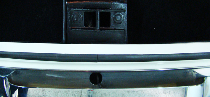 (4 - Protected Trunk Edge - Top View.jpg) (4 - Protected Trunk Edge - Top View.jpg)
Attachments
----------------
1 - White Profile.jpg (68KB - 753 downloads)
2 - Applied White Protective Profile.jpg (139KB - 765 downloads)
3 - Protective Profile fixed behind Trunk Seal.jpg (119KB - 749 downloads)
4 - Protected Trunk Edge - Top View.jpg (98KB - 731 downloads)
|
|
| |
|
Expert
Posts: 1215
Location: SWITZERLAND | Emblem on Ash Tray: As already shown earlier in this thread, I had fixed the small Knight Head (01) on the ash tray. It is the same as already on the steering wheel. Looking a little bit “lost”, I replaced it now by the more sophisticated emblem used on the Glove Box of the 1959 Coronet (02-03). If nicer to put there an emblem, particulary this new one depends on each personal taste (04-05). Anyway, as lover of emblems I like it. Another eye-catcher! - SERGE - :laugh:
Edited by sermey 2014-05-11 8:15 AM
 (01 Small Knight Head 25.jpg) (01 Small Knight Head 25.jpg)
 (02 1959 Glove Box Medaillon NOS 25.jpg) (02 1959 Glove Box Medaillon NOS 25.jpg)
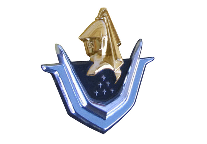 (03 1959 Glove Box Medaillon NOS Solo 25.jpg) (03 1959 Glove Box Medaillon NOS Solo 25.jpg)
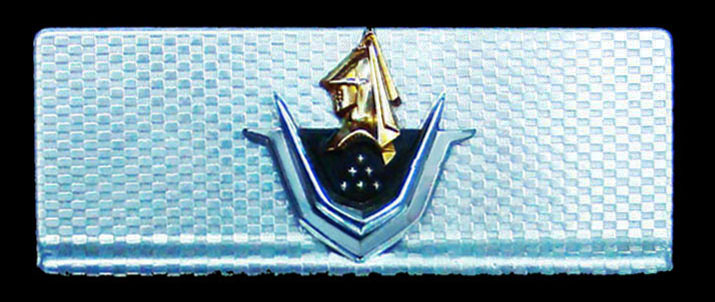 (04 Ash Tray Solo 25.jpg) (04 Ash Tray Solo 25.jpg)
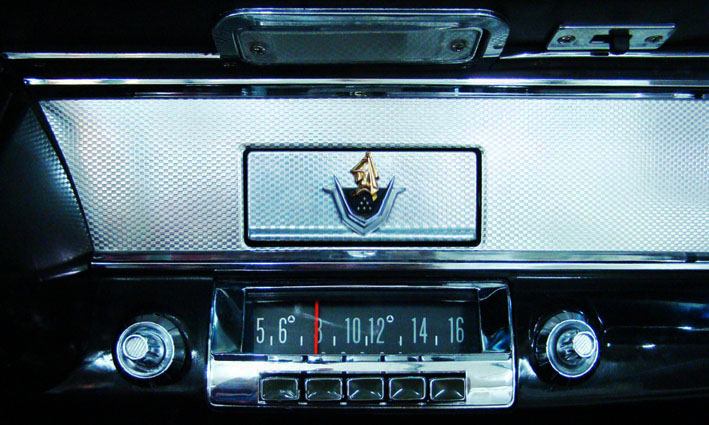 (05 Ash Tray Front View 25.jpg) (05 Ash Tray Front View 25.jpg)
Attachments
----------------
01 Small Knight Head 25.jpg (63KB - 687 downloads)
02 1959 Glove Box Medaillon NOS 25.jpg (95KB - 660 downloads)
03 1959 Glove Box Medaillon NOS Solo 25.jpg (63KB - 665 downloads)
04 Ash Tray Solo 25.jpg (88KB - 670 downloads)
05 Ash Tray Front View 25.jpg (119KB - 682 downloads)
|
|
| |
|
Expert
Posts: 1215
Location: SWITZERLAND | Bright Back Light: When replacing the bulbs by LEDs for backlight, there are various LED lamps available that fit to the socket 1156 BA (01). Here not shown all. The standard replacement LEDs shines more white then brighter. One solution for a brighter light is to use Super Bright LEDs, as the power dissipation and therefore the heating effect remains small. A next step brighter is to use instead of the 1156 BA single lamp the High Power 1157 BA dual Lamp (Turn Signal / Brake), when bridging the two connectors, and adapting one fixing pin to fit to the single contact socket (02). The difference between standard bulb and Power LED manifests in color and an impressive brightness (03). Now, turning backwards at night, the street is sufficient illuminated, in respect to ground and in distance (04). – SERGE -
Edited by sermey 2014-05-16 12:34 PM
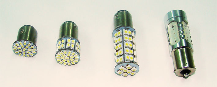 (01 Various LEDs BS1156 -25.jpg) (01 Various LEDs BS1156 -25.jpg)
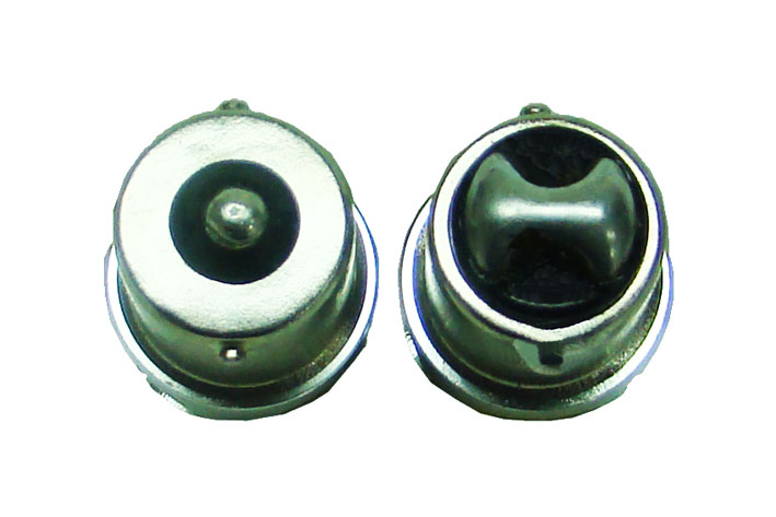 (02 Sockets BS1156 - BS1157 bridged -25 .jpg) (02 Sockets BS1156 - BS1157 bridged -25 .jpg)
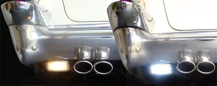 (03 Comparison Bulb - LED -25.jpg) (03 Comparison Bulb - LED -25.jpg)
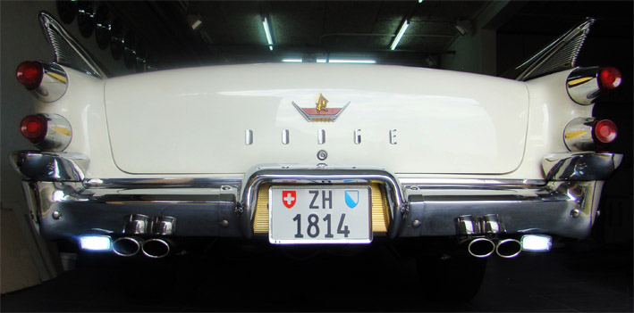 (04 Super Bright Back Light - 25.jpg) (04 Super Bright Back Light - 25.jpg)
Attachments
----------------
01 Various LEDs BS1156 -25.jpg (47KB - 693 downloads)
02 Sockets BS1156 - BS1157 bridged -25 .jpg (68KB - 664 downloads)
03 Comparison Bulb - LED -25.jpg (73KB - 666 downloads)
04 Super Bright Back Light - 25.jpg (80KB - 670 downloads)
|
|
| |
|
Board Moderator & Exner Expert 10K+
Posts: 13062
Location: Southern Sweden - Sturkö island | Nice idea Serge, thanks' for sharing! |
|
| |
|
Expert
Posts: 1215
Location: SWITZERLAND | The Last Emblem: Many years ago I found a nice ForwardLook Emblem with a Dodge Script. Because I liked I purchased, even I had never seen this one on a 1959 Dodge. It got a nice place under the left Front Seat (01). Since then I was looking for a similar Emblem for the right side, but without the Dodge Script - a ForwardLook Emblem should never be mounted Backward. Now I found what I was looking for a long time (02). It has got his reserved place, looking happily forward as his brother on the left side (03). Another hidden eye-catcher (04). Was this the last emblem to be mounted on my 1959 Dodge Convertible? - SERGE -
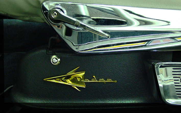 (01 FWL Emblem LH -25.jpg) (01 FWL Emblem LH -25.jpg)
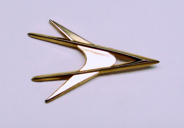 (02 FWL Emblem Solo-25.jpg) (02 FWL Emblem Solo-25.jpg)
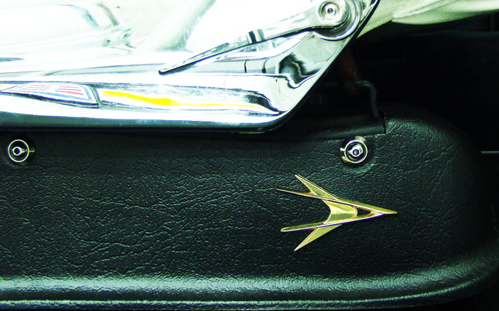 (03 Emblem RH -25.jpg) (03 Emblem RH -25.jpg)
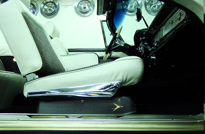 (04 FWL Emblem View RH -25 .jpg) (04 FWL Emblem View RH -25 .jpg)
Attachments
----------------
01 FWL Emblem LH -25.jpg (128KB - 632 downloads)
02 FWL Emblem Solo-25.jpg (61KB - 654 downloads)
03 Emblem RH -25.jpg (118KB - 613 downloads)
04 FWL Emblem View RH -25 .jpg (118KB - 651 downloads)
|
|
| |
|
Board Moderator & Exner Expert 10K+
Posts: 13062
Location: Southern Sweden - Sturkö island | That looks really like a nice emblem Serge - fact I don't recall ever seeing such a nicely shaped one?! Is there a story behind?? |
|
| |
|
Expert
Posts: 2788
Location: USA - KY |
Looks great, Serge!
Love your work. You are part mechanic, part artist!
Astounding attention to detail!
 |
|
| |
|
Expert
Posts: 1215
Location: SWITZERLAND | Flashing LEDs: Brighter light on directional and rear lamps can be achieved when using LEDs of the new generation (01). They about 10% current consumption then standard bulbs. With this low current the common thermostatic operated flasher (02) will not work anymore. Load resistors of about 6 Ohm/20Watt (03) are offered to connect in parallel to each replaced bulb. To keep it low-cost, one resistor can be connected directly at the output of the flasher and will then be parallel to any LEDs in flashing mode. With the load resistor the additional “advantage” of a lower current consumption is lost, but it works. Using an electronic controlled flasher (astable multivibrator) with relais (04), the flash frequency will be independent of the loading. It is defined by the time-constant, and can be modified by the value of a capacitor or resistor (05). Simpler is to use an adjustable electronic flasher (06), The pin configuration enables to replace directly the standard flasher. It needs an additional lead to ground. Now the flashing frequency can be modified manually in a wide range by turning the axis of the potentiometer, and independent of load and voltage it remains stable. The simplest and lowest cost solution at all is to keep all the bulbs connected, but outside the housing (in a thermo- protected and dimmed space), and insert the LED lamps in parallel. The total current will increase about 10% and as well the flashing frequency. The result with Power LEDs is a Super Bright Rear Light, when flashing and at stop. With the camera the brightest red becomes yellow (07)! To get a warmer and homogenous white light I covered the front LEDs with a Dessert Cap (08), only possible because the LED doesn’t heat. With parking LEDs ON, now the car can keep the battery charge up to one week, at super bright light! - SERGE - :laugh:
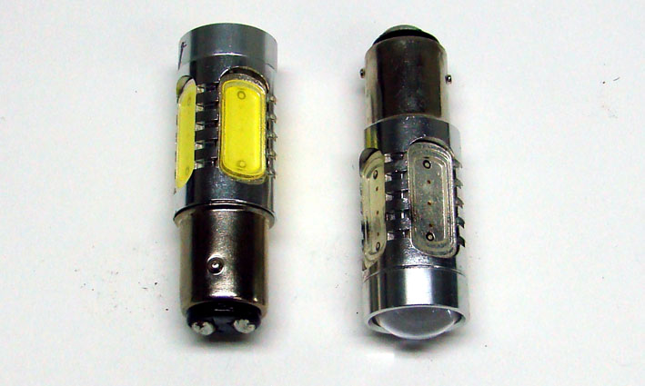 (01 Power LEDs Red-White Cree.jpg) (01 Power LEDs Red-White Cree.jpg)
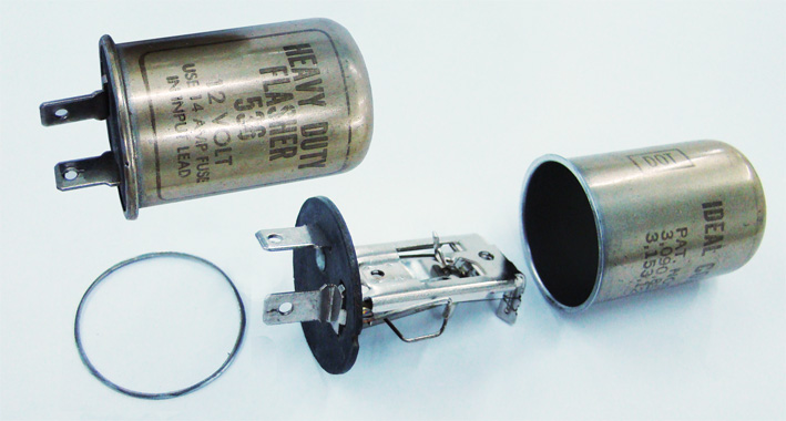 (02 Thermostatic Flasher.jpg) (02 Thermostatic Flasher.jpg)
 (03 Load Resistors.jpg) (03 Load Resistors.jpg)
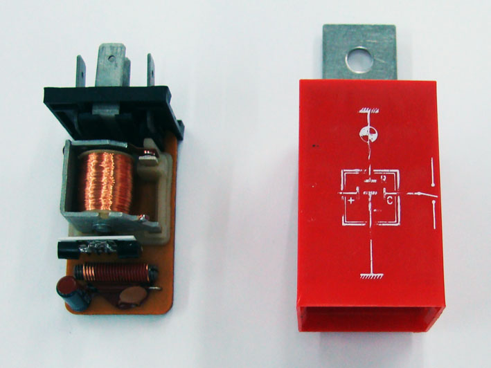 (04 Electronic Flasher.jpg) (04 Electronic Flasher.jpg)
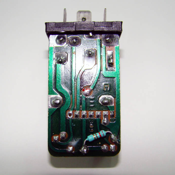 (05 Printed Circuit Board.jpg) (05 Printed Circuit Board.jpg)
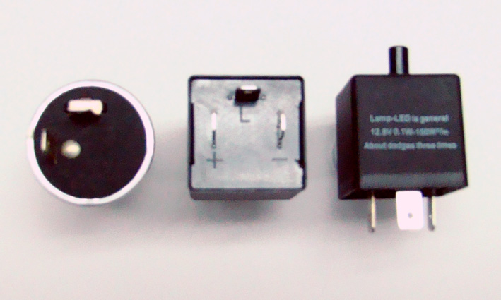 (06 Adjustable Electronic Flasher.jpg) (06 Adjustable Electronic Flasher.jpg)
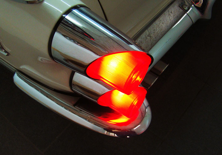 (07 Super Bright Red Light.jpg) (07 Super Bright Red Light.jpg)
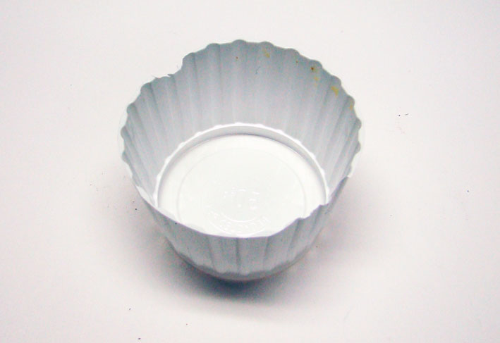 (08 Dessert Cap.jpg) (08 Dessert Cap.jpg)
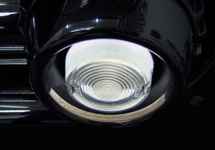 (09 Damped LED Park Light.jpg) (09 Damped LED Park Light.jpg)
Attachments
----------------
01 Power LEDs Red-White Cree.jpg (74KB - 628 downloads)
02 Thermostatic Flasher.jpg (93KB - 609 downloads)
03 Load Resistors.jpg (76KB - 613 downloads)
04 Electronic Flasher.jpg (72KB - 610 downloads)
05 Printed Circuit Board.jpg (93KB - 594 downloads)
06 Adjustable Electronic Flasher.jpg (93KB - 634 downloads)
07 Super Bright Red Light.jpg (96KB - 627 downloads)
08 Dessert Cap.jpg (51KB - 617 downloads)
09 Damped LED Park Light.jpg (80KB - 599 downloads)
|
|
| |
|
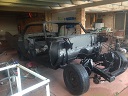
Expert 5K+
Posts: 8445
Location: Perth Australia | Very good
Always enjoy reading this thread (been a long time since something new)
I will add though that those "scotch locks" (red wire taps) belong in the bin, nothing but electrical gremlin makers especially on anything that draws a current
|
|
| |
|
Expert
Posts: 1215
Location: SWITZERLAND | Dash Pad 1: When I got my Dodge, the dash pad was hard, dried and partly broken. There was no other way then to remove it (01). After cleaning the surface I used the same black vinyl to coat it as for the door panels (02). Applying on both sides enough Contact Glue, as for the arm rests (see earlier post), the coating got softer, could then be stretched and pulled around the edges. Fixed with masking tape I had to wait one week. The instruments metallic insert (03) then mounted over when black painted. The right side rounding was simulated by a coated metal (04).The result was impressive, as shown in 06 – 08. There was just one negative aspect: the surface was not padded and there were no ribbers. Looking at the old brochure the ribbing is also missing (09), but I think this was a preliminary draft. The illustration in the parts book, the dash pad shows ribbes (10 black), as can be seen on cars with the original pad (11 blue, for Ron). Today the Swedish company RD Autoline (Tony) reproduces this one and many other dash pads in a stunning originality and at high quality standard. What I saw in documentations is a high skilled artwork. I ordered one for my 1959 Dodge Convertible and will later report the proceeding in mounting it, in: Dash Pad 2. - SERGE -
 (01 Remove Old Dash Board.jpg) (01 Remove Old Dash Board.jpg)
 (02 Black Vinyl Coating.jpg) (02 Black Vinyl Coating.jpg)
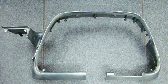 (03 Instruments Metallic Insert.jpg) (03 Instruments Metallic Insert.jpg)
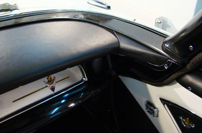 (04 Vinyl Coated Dash Right Side.jpg) (04 Vinyl Coated Dash Right Side.jpg)
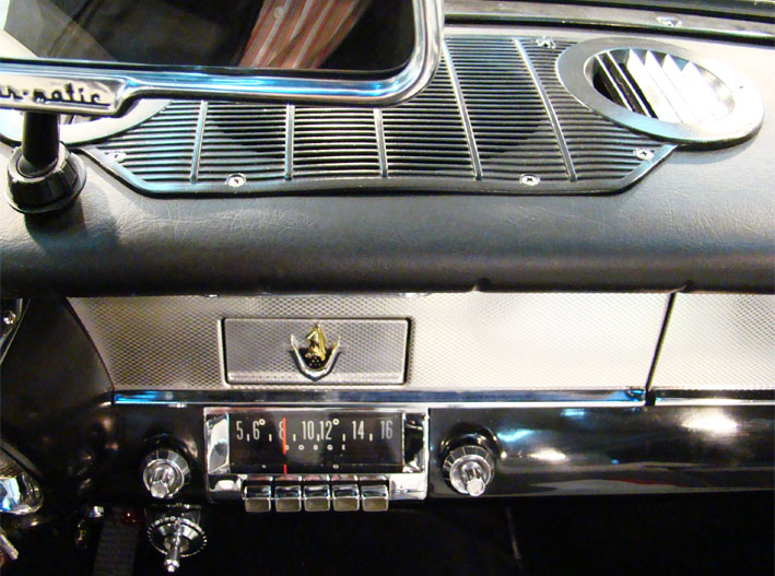 (05 Vinyl Coated Dash Center.jpg) (05 Vinyl Coated Dash Center.jpg)
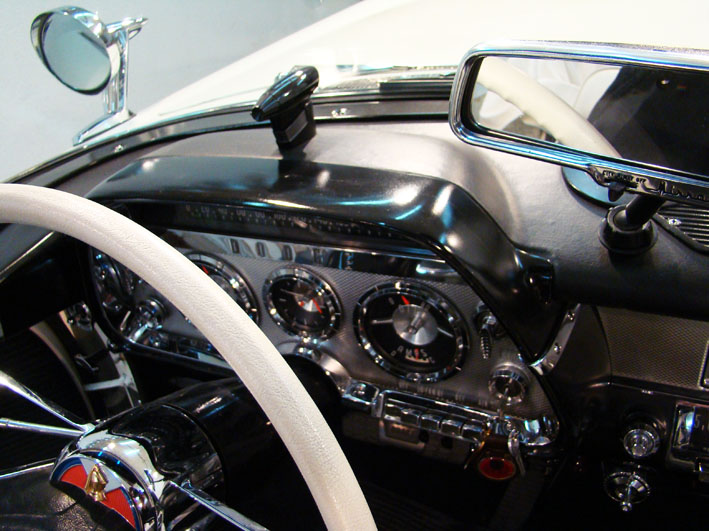 (06 Vinyl Coated Dash Left Side.jpg) (06 Vinyl Coated Dash Left Side.jpg)
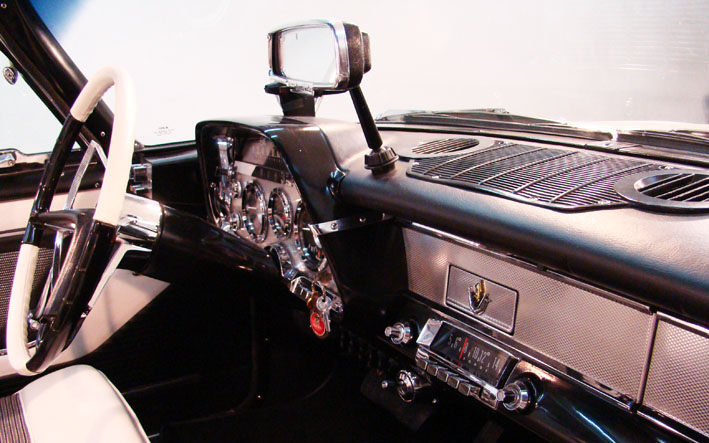 (07 Vinyl Coated Dash Board Overview.jpg) (07 Vinyl Coated Dash Board Overview.jpg)
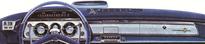 (08 Dash Pad Old Brochure.jpg) (08 Dash Pad Old Brochure.jpg)
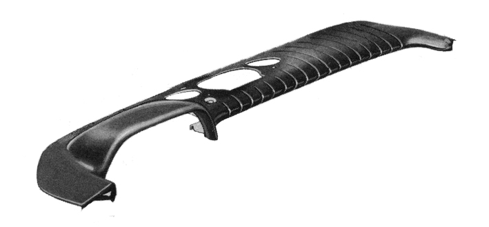 (09 Dash Pad Partsbook Black.jpg) (09 Dash Pad Partsbook Black.jpg)
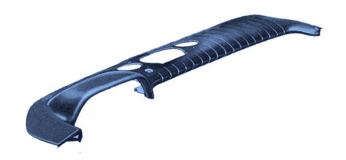 (10 Dash Pad Partsbook Blue.jpg) (10 Dash Pad Partsbook Blue.jpg)
Attachments
----------------
01 Remove Old Dash Board.jpg (91KB - 615 downloads)
02 Black Vinyl Coating.jpg (112KB - 632 downloads)
03 Instruments Metallic Insert.jpg (97KB - 590 downloads)
04 Vinyl Coated Dash Right Side.jpg (96KB - 631 downloads)
05 Vinyl Coated Dash Center.jpg (134KB - 634 downloads)
06 Vinyl Coated Dash Left Side.jpg (124KB - 589 downloads)
07 Vinyl Coated Dash Board Overview.jpg (112KB - 616 downloads)
08 Dash Pad Old Brochure.jpg (79KB - 595 downloads)
09 Dash Pad Partsbook Black.jpg (53KB - 611 downloads)
10 Dash Pad Partsbook Blue.jpg (93KB - 590 downloads)
|
|
| |
|
Expert
Posts: 1215
Location: SWITZERLAND | Weak Hood Spring: When I got my Dodge, the hood had to be kept up with a wooden bar because of weakened springs. Thus I had first to reproduce stronger springs, and found a manufacturer. For an incredible price of CHF 80.00 he produced for me (1994), according the sample I sent him, 3 different pairs of springs, so I could test them on the car (01) and make the choice. What you see are the remaining 2 new pairs. I kept the pair of spring that just hold up the hood and painted them in white as the car (02). Since then the hood is up as it should. - SERGE –
Edited by sermey 2015-04-08 12:05 PM
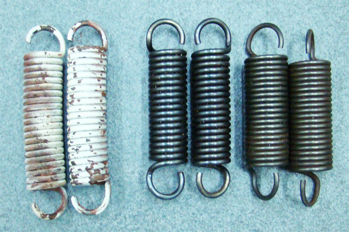 (01 Old-New Repro Hood Spring.jpg) (01 Old-New Repro Hood Spring.jpg)
 (02 Mounted New Hood Spring.jpg) (02 Mounted New Hood Spring.jpg)
Attachments
----------------
01 Old-New Repro Hood Spring.jpg (132KB - 578 downloads)
02 Mounted New Hood Spring.jpg (77KB - 651 downloads)
|
|
| |
|
Expert
Posts: 1530
Location: ZH, Switzerland | Hi Serge With a big interest I'm following your thred. You're like a Wizard here in Switzerland. Thank you very much for all your helpful hints. I'm sure I could use some of your hints for my Letter after it comes back from the body shop. I'm happy I could meet you at Zug on April 20th this year and we'll do the journey to the PBM together. Big hugs. Till later, take care, Dieter |
|
| |
|

Expert 5K+
Posts: 7468
Location: northern germany | hoodinki - 2015-04-08 12:13 PM
We all got that stick, I prefer the unscrewable wooden type on push brooms. I remember needing these, and a wheel chuck to keep in the trunk for parking on hills if you had a Powerflite, back in the 1970s for my Plymouth. Not really MBZ engineering going on back then. No wonder Plymouth is now Dead,.
wtf?! in 100 000s of miles driving my plymouth or other fls i never had the slightest problems with hood springs or the very efficient parking brakes. they lock the tires anytime and on the steepest hills. don't blame these fine cars for poor maintenance. these cars are build for the eternity IF properly serviced. |
|
| |
|
Expert
Posts: 1215
Location: SWITZERLAND | Front Light Connections: All wires of the front lights lead to a Terminal Block located in front of the battery (01). This Terminal Block has 5 connectors (1 – 5 from left to right). For a nicer appearance, it is fixed with polished stainless pan-head screws (M5), the connector bolts are covered with cap nuts, and the leading wires are hold in black (02). The schematic diagram can be found in the Service Manual DODGE 59 Supplement, here a part restricted to the front lights (03). The connections on my car are originally slightly different then shown in the manual (04). They could not be interchanged because of the exact length of the wires. There is a nice repro of the terminal connector available, at a reasonable price (05). The connections of the terminal block I added as well in PDF. - SERGE -
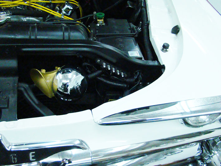 (01 Terminal Location.jpg) (01 Terminal Location.jpg)
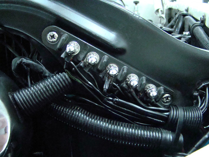 (02 Terminal Block.jpg) (02 Terminal Block.jpg)
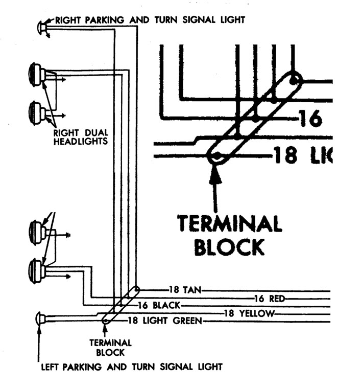 (03 Front Light Schematic.jpg) (03 Front Light Schematic.jpg)
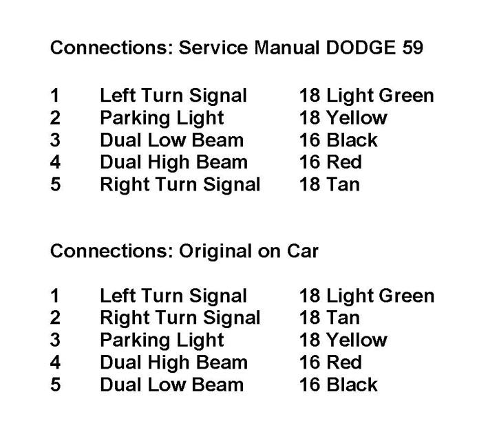 (04 Connections Terminal Block.jpg) (04 Connections Terminal Block.jpg)
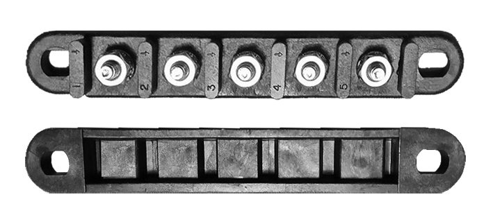 (05 Connector Repro.jpg) (05 Connector Repro.jpg)
Attachments
----------------
01 Terminal Location.jpg (118KB - 767 downloads)
02 Terminal Block.jpg (118KB - 735 downloads)
03 Front Light Schematic.jpg (91KB - 710 downloads)
04 Connections Terminal Block.jpg (77KB - 720 downloads)
05 Connector Repro.jpg (101KB - 721 downloads)
06 Connections Terminal Block.pdf (6KB - 747 downloads)
|
|
| |
|
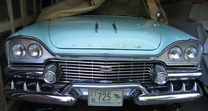
Location: The Mile High City | outstanding, Serge - I always enjoy reading this thread. Your attention to detail and inventiveness is remarkable. |
|
| |
|
Board Moderator & Exner Expert 10K+
Posts: 13062
Location: Southern Sweden - Sturkö island | Always interesting to read Serges posts - careful work to enhance the car |
|
| |
|
Expert
Posts: 1215
Location: SWITZERLAND | Push Buttons: When restoring the Push Buttons a time ago, I had to remove the old paint in the letters. All chemical way where to aggressive, I used a soft diluent to be cleaned with water. But this plastic is so “weak”, that not only the paint was removed, but as well the front was badly affected. I had to grind it down and then use letter sticker (01), protected by a transparent foil (02). Most Push Buttons are irreparably damaged by Finger Nails. It is very rare to find one with intact letters (03). Finally I found now a set in acceptable condition (04). This time I didn’t use any chemistry at all (05), cleaned them with a soft brass brush (06), and got them all quite nice (07). The paint for the letters (red as used for the Instuments) I applied locally with a needle, removed instantly the color around with a rubber scraper, and when dried grinded the front (08). To fix and center the caps I put some tape around (white), inserted again a protective transparent foil, and for a soft return I added an O-Ring over the cap (09). Now the Push Buttons look again as they should and are protected from Finger Nails: Clear letters and nice to look at. - SERGE -
Edited by sermey 2015-04-24 3:12 AM
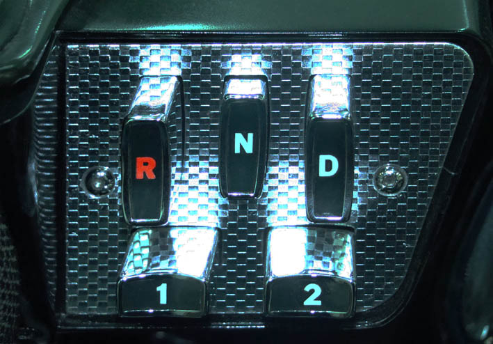 (01 Push Buttons restored.jpg) (01 Push Buttons restored.jpg)
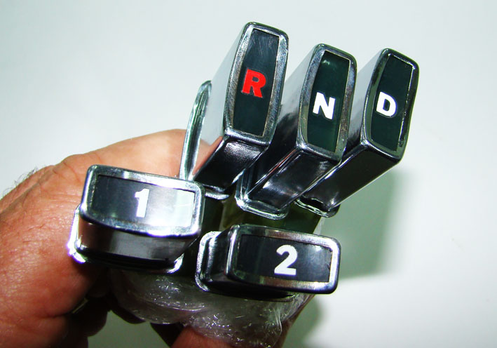 (02 Sticked Letters.jpg) (02 Sticked Letters.jpg)
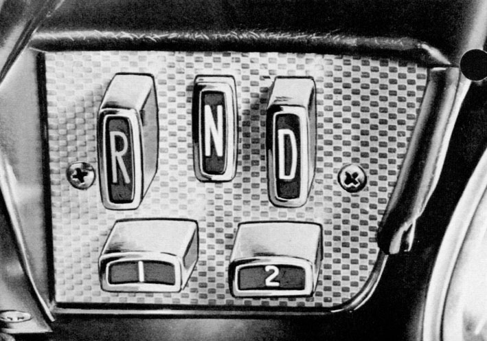 (03 Push Buttons Ross Roy.jpg) (03 Push Buttons Ross Roy.jpg)
 (04 Used Push Button.jpg) (04 Used Push Button.jpg)
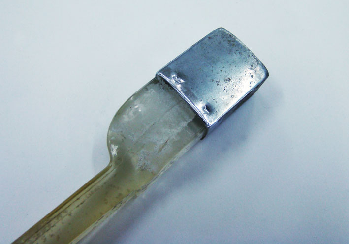 (05 Push Button Unrestored.jpg) (05 Push Button Unrestored.jpg)
 (06 Brush-up Push Buttons.jpg) (06 Brush-up Push Buttons.jpg)
 (07 Push Buttons AC brushed.jpg) (07 Push Buttons AC brushed.jpg)
 (08 Grinding Front Rounded.jpg) (08 Grinding Front Rounded.jpg)
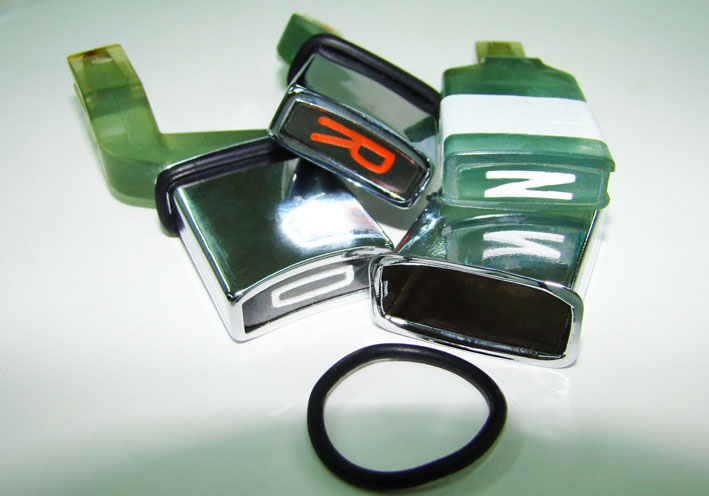 (09 Push Button Assembly.jpg) (09 Push Button Assembly.jpg)
 (10 Push Button Unit Mounted.jpg) (10 Push Button Unit Mounted.jpg)
Attachments
----------------
01 Push Buttons restored.jpg (104KB - 761 downloads)
02 Sticked Letters.jpg (80KB - 775 downloads)
03 Push Buttons Ross Roy.jpg (117KB - 724 downloads)
04 Used Push Button.jpg (113KB - 759 downloads)
05 Push Button Unrestored.jpg (60KB - 751 downloads)
06 Brush-up Push Buttons.jpg (80KB - 747 downloads)
07 Push Buttons AC brushed.jpg (58KB - 738 downloads)
08 Grinding Front Rounded.jpg (90KB - 745 downloads)
09 Push Button Assembly.jpg (77KB - 786 downloads)
10 Push Button Unit Mounted.jpg (115KB - 766 downloads)
|
|
| |
|
Board Moderator & Exner Expert 10K+
Posts: 13062
Location: Southern Sweden - Sturkö island | Lot of patience and love for the work at hand - those pushbuttons could'nt be any better. |
|
| |
|
Expert
Posts: 1215
Location: SWITZERLAND | Six-Way Seat Adjuster Switch: By a single bar of the switch, all six positions of the seat can be adjusted (01). Forward - Backward (5 inches) Higher - Lower (2 inches) Tilt CW - CCW (18 degrees) (02). As the initial current of the seat adjustment is quite high, the contacts should be checked from time to time (03) (04). The color of the wires must be correct, the switch is folded down for rear view (05). Later I found another switch as spare part, mounted on a chrome bezel, as illustrated in the owners manual (06). This bezel should be on front side of the seat. To keep the nice golden emblem I put it reversed on the rear side - and it fits as it should be. The top view shows the mounting bracket and the power seat motor (07). The red main wire is connected after the circuit breaker located on the top lift switch, this as well the power windows. The chrome bezel is mounted with the two existing screws of the switch, thus easy to remove if one day dislike. But for now, a bit more chrome on my Convertible! (08) – SERGE -
Edited by sermey 2015-04-29 9:26 AM
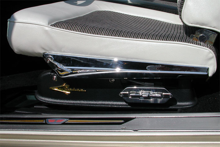 (01 Six-Way Power Switch.jpg) (01 Six-Way Power Switch.jpg)
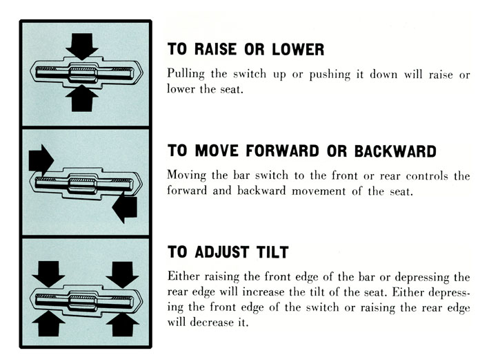 (02 Six-Way Seat Adjustments.jpg) (02 Six-Way Seat Adjustments.jpg)
 (03 Contact Elements.jpg) (03 Contact Elements.jpg)
 (04 Power Switch Components.jpg) (04 Power Switch Components.jpg)
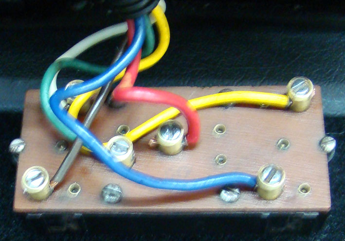 (05 Connections Rear View.jpg) (05 Connections Rear View.jpg)
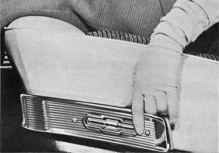 (06 Six-Way Power Switch Owners Manual 25 .jpg) (06 Six-Way Power Switch Owners Manual 25 .jpg)
 (07 Top View with Power Seat Motor.jpg) (07 Top View with Power Seat Motor.jpg)
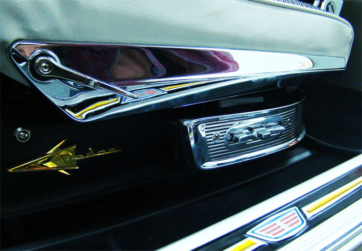 (08 Power Switch with Chrome Bezel.jpg) (08 Power Switch with Chrome Bezel.jpg)
Attachments
----------------
01 Six-Way Power Switch.jpg (103KB - 734 downloads)
02 Six-Way Seat Adjustments.jpg (92KB - 770 downloads)
03 Contact Elements.jpg (67KB - 724 downloads)
04 Power Switch Components.jpg (82KB - 750 downloads)
05 Connections Rear View.jpg (102KB - 757 downloads)
06 Six-Way Power Switch Owners Manual 25 .jpg (121KB - 738 downloads)
07 Top View with Power Seat Motor.jpg (110KB - 752 downloads)
08 Power Switch with Chrome Bezel.jpg (116KB - 728 downloads)
|
|
| |
|
Expert
Posts: 1530
Location: ZH, Switzerland | Thank you very much Serge for this information. In my Letter I got a six way electric adjustable drivers seat as well. The switch looks different on a 1960 Mopar, but I assume the basic function is the same - one motor, three clutches. Happy Motoring! Dieter |
|
| |
|
Expert
Posts: 2643
Location: Minor Hill, TN | Thank You for the 411 |
|
| |
|
Expert
Posts: 1215
Location: SWITZERLAND | Dome Lamp: With time the plastic lens goes brown and burns out in the center, due to excessive heat by the bulb. This is already observable in the original brochure of the 1959 Dodge Convertible, burned lens zoomed right down (01). As these lenses are highly demanded, reproductions are available up to USD 80 a pair (02). A single NOS Dome Lamp Lens Imperial with crown insigna is offered for USD155 (03). To replace the lens, the fixing pins on the rear shell have to be bent out with the result that they mostly break off. Therefore break out one of the three pins for the lens can be removed, replace it by a soldered one, and grind a slot in the metal retainer. Now it can be fixed or removed anytime just by twisting (04). To avoid a newly deformation of the replaced lens by heat a LED, no longer then 35mm, is advised in replacement of the bulb (05). This special bulb has two terminals, plus and minus, the socket is isolated, means not grounded. One pin is connected to plus, the other pin to minus when the door switch is activated. As I could not find such a LED I had to do some “surgical” interventions: - Unsolder the two contacts and the four fixing points of the socket for removal (06). - Socket removed (07). As shown, one contact leads direct to the LED unit for a bright light, the other contact to the same point but over a resistor of 15 Ohm for a lower light. The ground (-) goes to the socket, as expected (07). - Connect the resistor to minus (for lower light), and cut out the cupper of the printed circuit board in order to disconnect the ground (08). - Resolder the socket on the LED unit as it was previously. The LED has become a direct replacement of the original bulb (09). Now the dome lamp shows a brighter white light, without any burning of the plastic lens (10). - SERGE - P.S. Numbering of the pictures corrected.
Edited by sermey 2015-05-03 9:08 PM
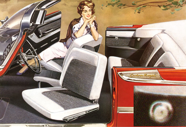 (01 Brochure Dome Lamp.jpg) (01 Brochure Dome Lamp.jpg)
 (02 NOS Dome Lamp Lense.jpg) (02 NOS Dome Lamp Lense.jpg)
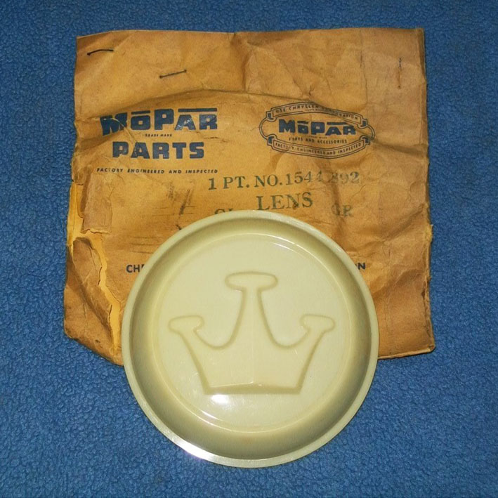 (03 NOS Dome Lamp Lense Imperial.jpg) (03 NOS Dome Lamp Lense Imperial.jpg)
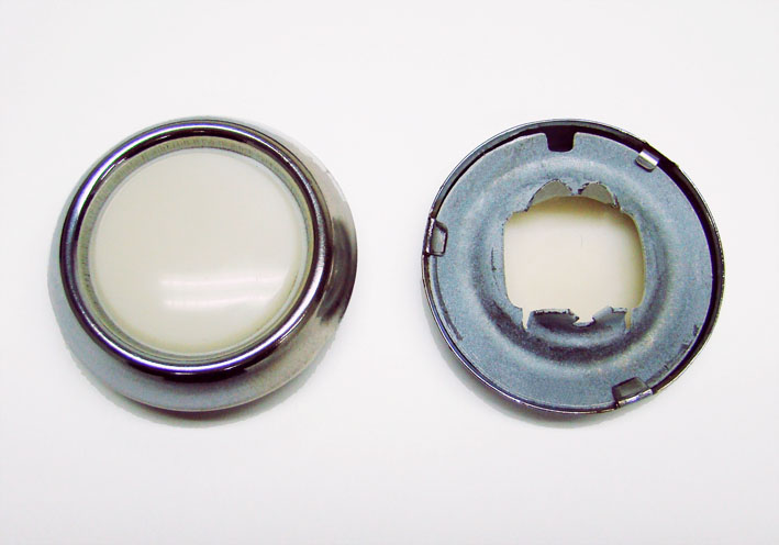 (04 Twist Rear Shell for Removal.jpg) (04 Twist Rear Shell for Removal.jpg)
 (05 Comparison LED - Bulb.jpg) (05 Comparison LED - Bulb.jpg)
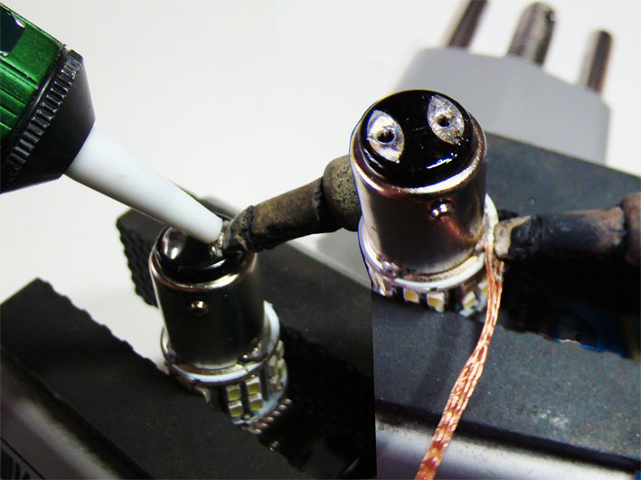 (06 Socket Removal.jpg) (06 Socket Removal.jpg)
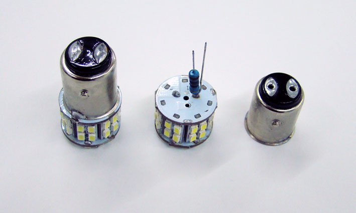 (07 Socket Removed.jpg) (07 Socket Removed.jpg)
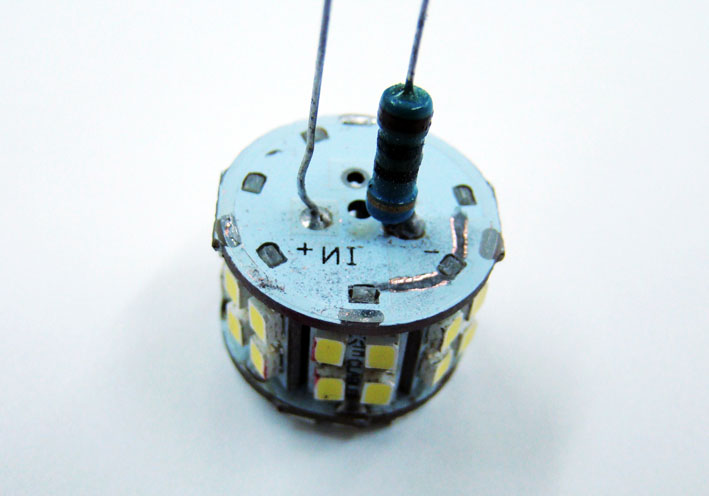 (08 Resistor on Minus and Ground Cut.jpg) (08 Resistor on Minus and Ground Cut.jpg)
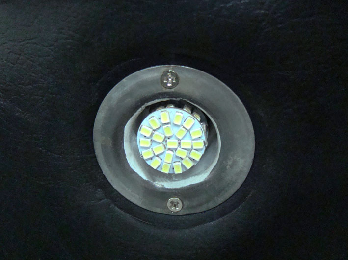 (09 Modified LED Inserted.jpg) (09 Modified LED Inserted.jpg)
 (10 Bright White Dome Light.jpg) (10 Bright White Dome Light.jpg)
Attachments
----------------
01 Brochure Dome Lamp.jpg (132KB - 764 downloads)
02 NOS Dome Lamp Lense.jpg (81KB - 709 downloads)
03 NOS Dome Lamp Lense Imperial.jpg (137KB - 710 downloads)
04 Twist Rear Shell for Removal.jpg (61KB - 714 downloads)
05 Comparison LED - Bulb.jpg (66KB - 743 downloads)
06 Socket Removal.jpg (91KB - 758 downloads)
07 Socket Removed.jpg (50KB - 707 downloads)
08 Resistor on Minus and Ground Cut.jpg (60KB - 747 downloads)
09 Modified LED Inserted.jpg (81KB - 774 downloads)
10 Bright White Dome Light.jpg (114KB - 698 downloads)
|
|
| |
|
Expert
Posts: 1215
Location: SWITZERLAND | Car Production Broadcast: My restored Car Production Broadcast I had already presented a time ago in the appropriate forum. In this thread here I just show HOW I did it, not must be the best way to go – but it works. Scan the sheet with 1200dpi in precise vertical/horizontal orientation with Photoshop. It needs Win7 64-bit with at least 8MB RAM. The original scan is in the first layer named background (01). The layer 00 is a copy of the background in case of a disaster. . . . (01). Create the next layers 01 – 06 for individual mastering, and freeze them from moving (02). The layer 01 is the background pattern of the sheet, sample taken in a clean segment in layer 00. Remember, this background in not a uniform color, thus a pattern! Next copy the selected items from layer 00 into the designated layers as shown in (02), ready there for clean and restore individually. If the result in a layer is not satisfactory, then just delete and re-copy it. Examples of restored layers: Layer 02: Original Text with Grid brown (03). Layer 03: Original Typed Numbers black (04). The typed numbers are not upgraded as they could be in order to keep their authentification. When all layers have been restored, merge all in one layer to stay fixed. This will be the final Car Production Broadcast Restored, saved here in a smaller resolution, as JPG-Picture (05), or 1 : 1 as PDF-File with 144dpi (because of the 250k limitation) (08). The letters and the grid can as well be reproduced instead restored. Here the letters then are taken from the font library (Arial, Bold, Smooth, Color RGB: 207-113-46) and the lines are created by construction, all in Photoshop. In direct comparison to the original in the left, the difference is hardly visible (06). The Original Typed Numbers remains as before (04). Each single number can be selected, copied and inserted individually for another specific sheet (07). Now, any missing Car Production Broadcast can be re-created by anyone. Happy printing! - SERGE -
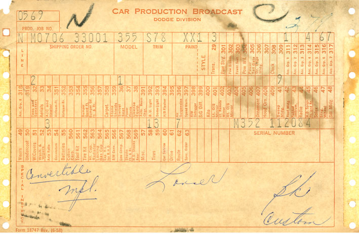 (01 Car Production Broadcast Scanned in.jpg) (01 Car Production Broadcast Scanned in.jpg)
 (02 Layers Listing.jpg) (02 Layers Listing.jpg)
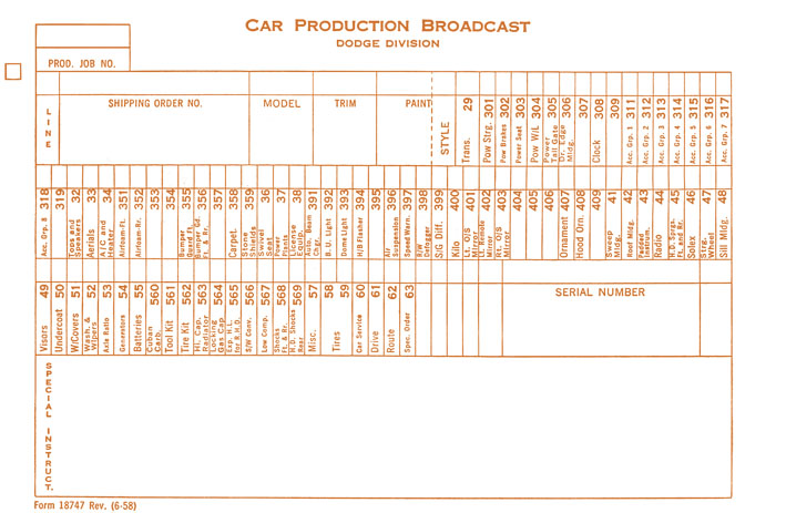 (03 Original Text with Grid.jpg) (03 Original Text with Grid.jpg)
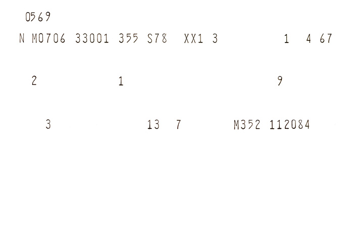 (04 Original Typed Numbers black.jpg) (04 Original Typed Numbers black.jpg)
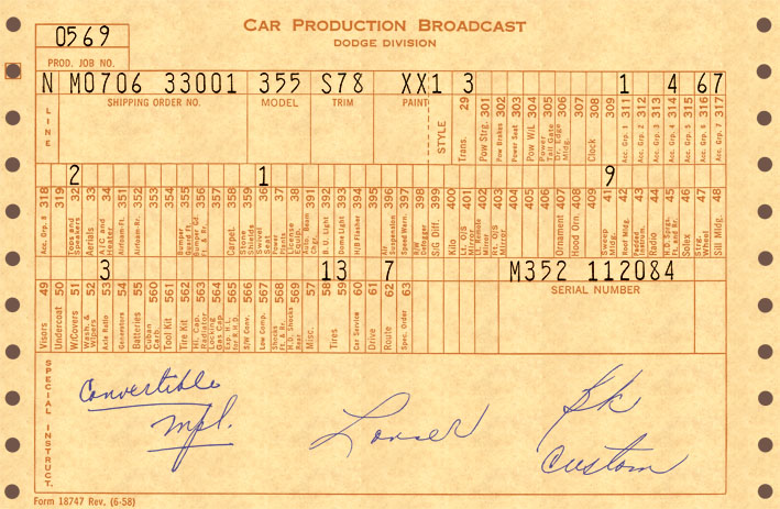 (05 Car Production Broadcast Restored.jpg) (05 Car Production Broadcast Restored.jpg)
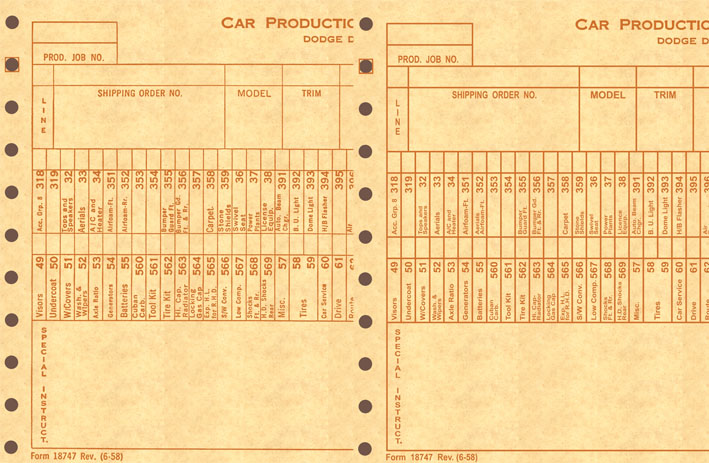 (06 Comparison Original Text - New Font.jpg) (06 Comparison Original Text - New Font.jpg)
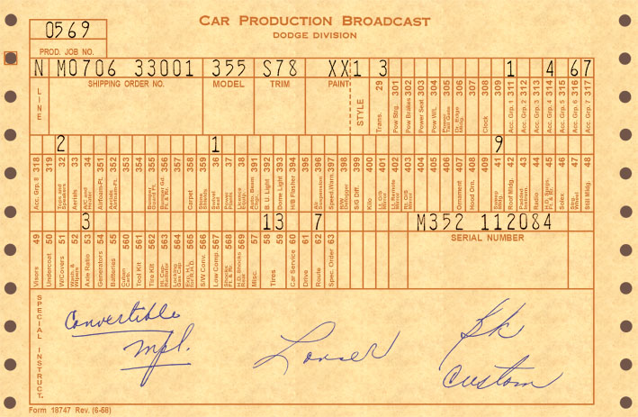 (07 Car Production Broadcast New Texted.jpg) (07 Car Production Broadcast New Texted.jpg)
Attachments
----------------
01 Car Production Broadcast Scanned in.jpg (123KB - 785 downloads)
02 Layers Listing.jpg (118KB - 713 downloads)
03 Original Text with Grid.jpg (119KB - 739 downloads)
04 Original Typed Numbers black.jpg (40KB - 714 downloads)
05 Car Production Broadcast Restored.jpg (132KB - 749 downloads)
06 Comparison Original Text - New Font.jpg (122KB - 732 downloads)
07 Car Production Broadcast New Texted.jpg (137KB - 744 downloads)
08 Car Production Broadcast Restored 144dpi.pdf (120KB - 770 downloads)
|
|
| |
|
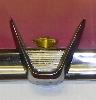
Elite Veteran
Posts: 1168
Location: D-70199 Heslach | Serge, It's great to "restore" all the history what comes with the car. Great work! |
|
| |
|
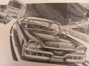
Exner Expert 19,174 posts. Neil passed away 18 Sep 2015. You will be missed, Neil!
Posts: 19146
Location: bishop, ca | PM sent (very-soon!)
|
|
| |
|
Expert
Posts: 1215
Location: SWITZERLAND | License Plate Lamp: For a brighter light the bulb can as well be replaced by a LED. The lamp unit is fixed with a bracket (01) (02). The heat of the bulb, consuming 5W, causes the lens to melt partially (03). As replacement I used the same LED as for the dome lights. The contacts here are brigded for a full power (04). The fixing pins on the LED can be left as is. Just bent out the tab, on the concerned side of the lamp socket, for turning the LED in, view one side and the other side (05). Now the license plate shines brighter at lower power consumption, and without melting the lens anymore (06). - SERGE -
Edited by sermey 2015-05-20 6:15 AM
 (01 Lamp Unit.jpg) (01 Lamp Unit.jpg)
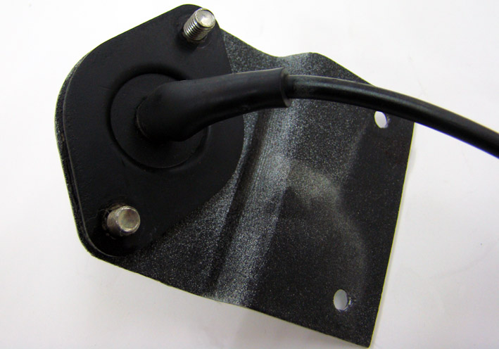 (02 Lamp Unit Rear View.jpg) (02 Lamp Unit Rear View.jpg)
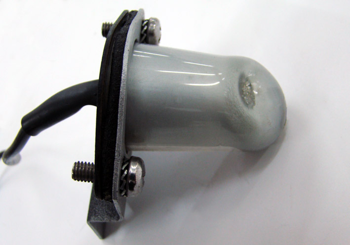 (03 Melted Lens.jpg) (03 Melted Lens.jpg)
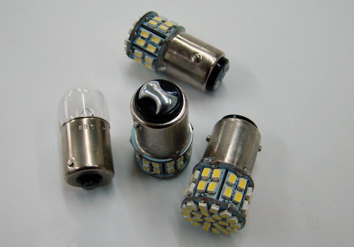 (04 Bulb 5W - LED.jpg) (04 Bulb 5W - LED.jpg)
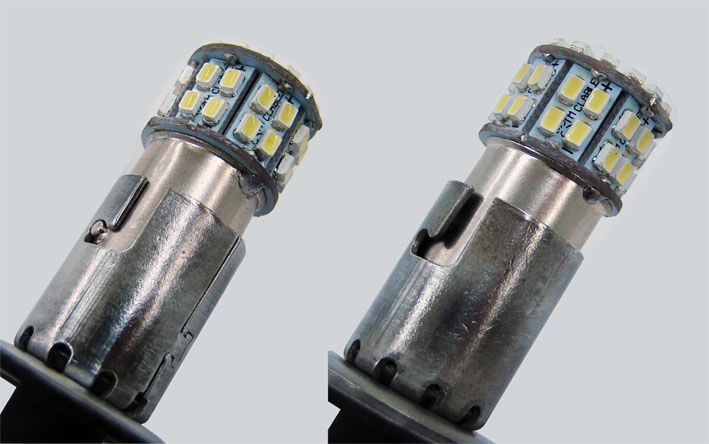 (05 Lamp Socket Bent.jpg) (05 Lamp Socket Bent.jpg)
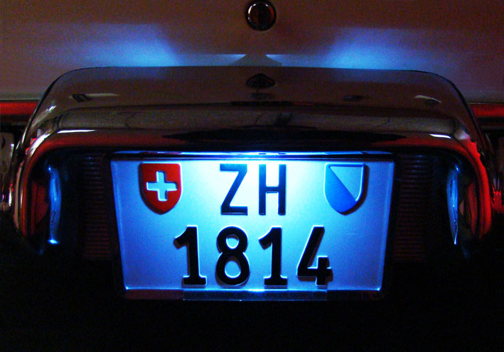 (06 Bright License Plate.jpg) (06 Bright License Plate.jpg)
Attachments
----------------
01 Lamp Unit.jpg (72KB - 742 downloads)
02 Lamp Unit Rear View.jpg (84KB - 712 downloads)
03 Melted Lens.jpg (71KB - 750 downloads)
04 Bulb 5W - LED.jpg (88KB - 703 downloads)
05 Lamp Socket Bent.jpg (80KB - 707 downloads)
06 Bright License Plate.jpg (100KB - 703 downloads)
|
|
| |
|
Expert
Posts: 1530
Location: ZH, Switzerland | Hell! It looks wonderful. Thank you very much Serge. Did you know, there are LED lamps available with a BA15d socket with to connection points? Kind regards, Dieter
Edited by di_ch_NY56 2015-05-20 6:08 AM
|
|
| |
|
Expert
Posts: 1215
Location: SWITZERLAND | . . . Did you know, there are LED lamps available with a BA15d socket with to connection points? . . . Yes Dieter, but I wanted the brightest light by using a "STOP"- LED that fits in the lamp unit. - SERGE -
Edited by sermey 2015-05-20 3:14 PM
|
|
| |
|
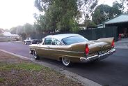
Extreme Veteran
Posts: 594
Location: Melbourne, Australia | Love this thread, Sermey; beautiful work on a perfect restoration IMHO.... great idea with the low fuel warning and the thermoplastic work. It would take me a lifetime to reach this standard of restoration... There is a fuel pump relay which has a trigger from the distributor I believe. It senses revs above cranking speed and only supplies power in this senario... upon stalling ( zero revs) power and thus fuel pump are inoperative..,. Colin |
|
| |
|
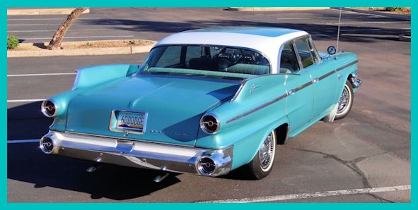
Expert
Posts: 2312
Location: Arizona | Some fuel pump relays get their power thru an oil pressure switch. So when the revs drop to zero and oil pressure also drops to zero the fuel pump power is shut off. |
|
| |
|
Expert
Posts: 1215
Location: SWITZERLAND | Glove Box Compartment: A Crypton bulb type produces a whiter light but consumes some more power (01). As LED replacement I selected the long type (02). The diffusion of the light is circular, as needed for this application (03). Just swap the devices? No, the socket of the bulb with integrated switch has reversed polarity (04). The (+) of the bulb will be grounded, at reversed voltage the LED cannot work. In order to keep this socket as original, there was no other way then to interchange the LED connections, as already shown. De-solder the connection and the lamp socket can be removed, for it is just pushed on the plastic base (05). That’s why I had some problems to mount the LED, I turned the LED-Unit whereas the lamp socket didn’t. Then reverse the polarity in the LED and extend the wire (06), push on the lamp socket, solder and glue it (07). Done. As my built-in radio covers partly the illumination, I added a LED-Array (08) in parallel to the replacement LED. It is supplied by two wires, the red wire is soldered on a (+12V) pad in front of the unit, the blue wire (GRD) now on the lamp socket (09). Then again: Push on the lamp socket, solder and glue it (10). Checking the set at reduced voltage (for picture), both lamps work together as one unit (11) and is ready for mount. Backside the LED-Array there is an adhesive surface for easy fixing, here on bottom of the radio. Except the side walls, I have covered the box inside with a black carpet inlay, a rest of my cars carpet (12). Then the right edge of the glove box has become damaged in friction with the metal door arm (13). For protection I inserted a plastic profile as used to fix paper sheets (13). This edge now is protected from further stress with the door arm (14). Finally, the glove box compartment shows an evenly spread illumination and the interior looks nice (15). – SERGE - :laugh:
 (01 Glove Box Bulb.jpg) (01 Glove Box Bulb.jpg)
 (02 Bulb and replacement LEDs.jpg) (02 Bulb and replacement LEDs.jpg)
 (03 Long LED ON.jpg) (03 Long LED ON.jpg)
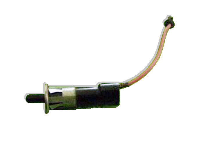 (04 Lamp Socket with Switch.jpg) (04 Lamp Socket with Switch.jpg)
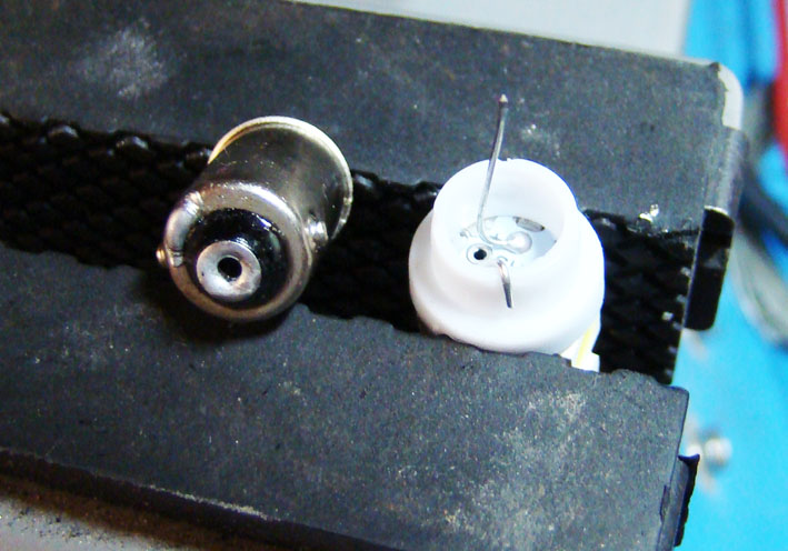 (05 LED Socket removed.jpg) (05 LED Socket removed.jpg)
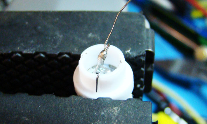 (06 LED Polarity reversed.jpg) (06 LED Polarity reversed.jpg)
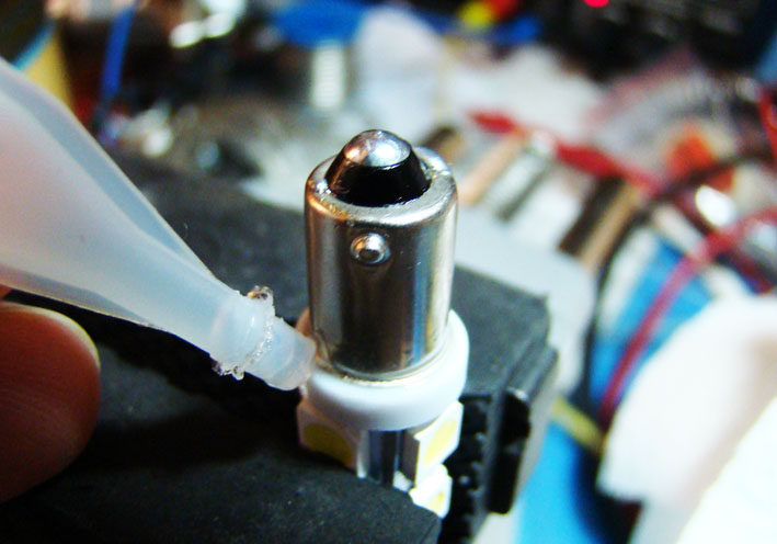 (07 LED Socket pushed on - soldered - glued.jpg) (07 LED Socket pushed on - soldered - glued.jpg)
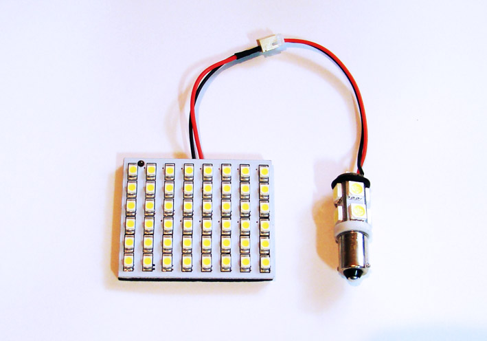 (08 LED Array 12V.jpg) (08 LED Array 12V.jpg)
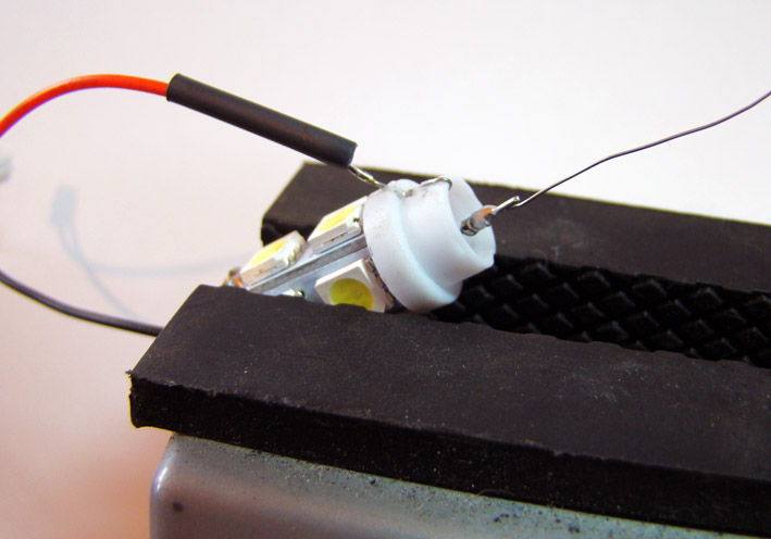 (09 Plus on LED Socket.jpg) (09 Plus on LED Socket.jpg)
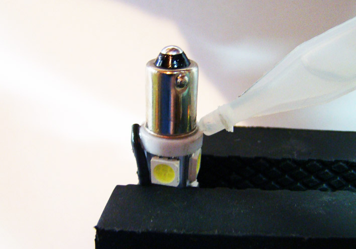 (10 Fixing the LED Socket.jpg) (10 Fixing the LED Socket.jpg)
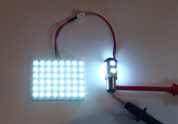 (11 Checking the Set.jpg) (11 Checking the Set.jpg)
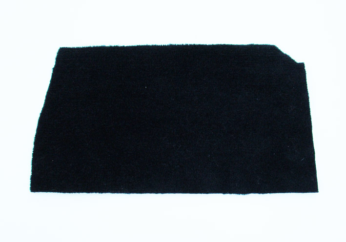 (12 Black Carpet Overlay.jpg) (12 Black Carpet Overlay.jpg)
 (13 Right Box Edge Damaged.jpg) (13 Right Box Edge Damaged.jpg)
 (14 Plastic Profile.jpg) (14 Plastic Profile.jpg)
 (15 Exposed Edge Protected.jpg) (15 Exposed Edge Protected.jpg)
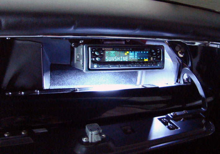 (16 Final Glove Box Compartment.jpg) (16 Final Glove Box Compartment.jpg)
Attachments
----------------
01 Glove Box Bulb.jpg (96KB - 711 downloads)
02 Bulb and replacement LEDs.jpg (69KB - 703 downloads)
03 Long LED ON.jpg (64KB - 727 downloads)
04 Lamp Socket with Switch.jpg (43KB - 730 downloads)
05 LED Socket removed.jpg (96KB - 696 downloads)
06 LED Polarity reversed.jpg (82KB - 722 downloads)
07 LED Socket pushed on - soldered - glued.jpg (88KB - 713 downloads)
08 LED Array 12V.jpg (81KB - 727 downloads)
09 Plus on LED Socket.jpg (82KB - 731 downloads)
10 Fixing the LED Socket.jpg (77KB - 703 downloads)
11 Checking the Set.jpg (64KB - 711 downloads)
12 Black Carpet Overlay.jpg (66KB - 690 downloads)
13 Right Box Edge Damaged.jpg (104KB - 691 downloads)
14 Plastic Profile.jpg (57KB - 749 downloads)
15 Exposed Edge Protected.jpg (94KB - 699 downloads)
16 Final Glove Box Compartment.jpg (93KB - 728 downloads)
|
|
| |
|
Expert
Posts: 2312
Location: Arizona | Speaking of LEDs, My turn signal lenses have darkened with time to the point where you can't even tell when the signals are on during the day. I did some checking and the #57 indicator bulbs put out about 3 candlepower. I found some replacement green LEDs that put out about 9 cp at www.superbrightleds.com . I put them in for the turn signal indicators and a red LED for the high beams and now I can see my indicator lights in daylight!!!
Photos in my album http://www.forwardlook.net/forums/photos/photo-thumbnails.asp?album... |
|
| |
|
Elite Veteran
Posts: 1168
Location: D-70199 Heslach | Serge,
your car was pictured by a friend
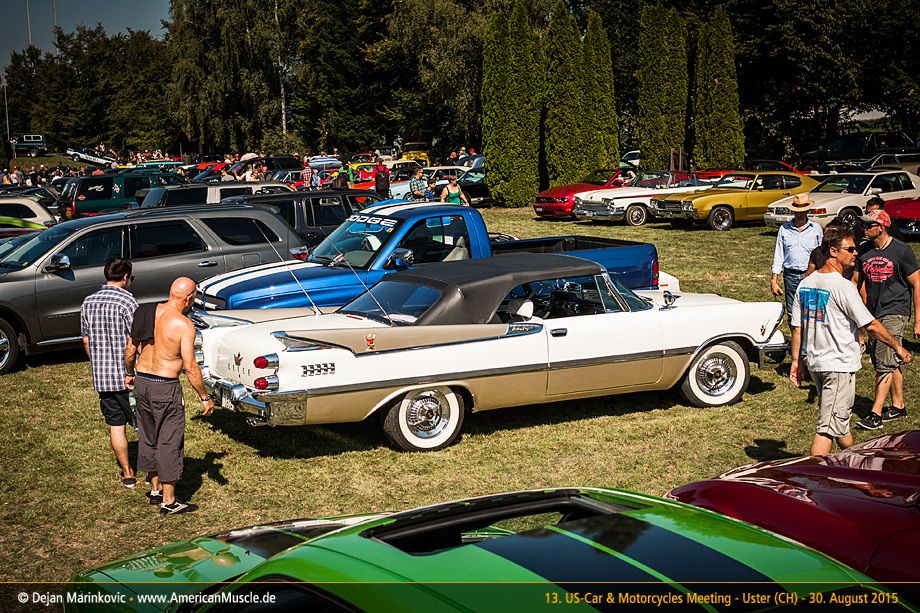 (2015-Schweiz_Uster-041x.jpg) (2015-Schweiz_Uster-041x.jpg)
Attachments
----------------
2015-Schweiz_Uster-041x.jpg (191KB - 674 downloads)
|
|
| |
|
Expert
Posts: 1215
Location: SWITZERLAND | Thank you for posting, Tom. It was a very hot day, therefore my car with top up - and some people topless! - SERGE - |
|
| |
|
Expert
Posts: 1215
Location: SWITZERLAND | Cable for Set the Time: The time of the electric clock on the 59 DODGE is being set by a separate control knob mounted under the dashboard (01). The original time setting cable at 30cm length is too short for remove the instruments unit without disconnect it (02). Not only, the white vinyl shell has become stiff due to age and thus, any used replacement I purchased, was broken on the clockside end. I found a replacement Scooter Speedometer Cable (04), with similar coupling to the clock (05). This new coupler including the core, original 3.2mm – new 3.0mm, could be used as is with small modifications (06). Just extend the gap and reduce the length as the sample (07). This highly flexible metal shelI must be cut on both sides to the new length by grinding (08). When heating the connectors, the vinyl shell of the old cable can be removed easily on both sides (09)(10). As soldered the connection will never come out again: Tin first the junction surfaces of both parts (11). Then when heated push the shell into the connector, it just fits (12). Because the old core couldn’t be removed from the control axis, the pressed part had to be grinded around. Deepen the so shortened hole of the control axis (3,2mm) by 8mm. The control axis and the new core are glued with a strong Cyanolit, always respecting the original working distances. Don't forget to insert the spring before! A fine tuning of the functionality can be done by heating the soldered connector and moving it, in order to extend or reduce the length up to 1mm, this on both sides of the control cable (13). Now, the new remote cable for set the time is ready to mount, works as the original one, but is much longer, with a steel shell and again flexible (14). – SERGE -
Edited by sermey 2015-09-12 10:57 AM
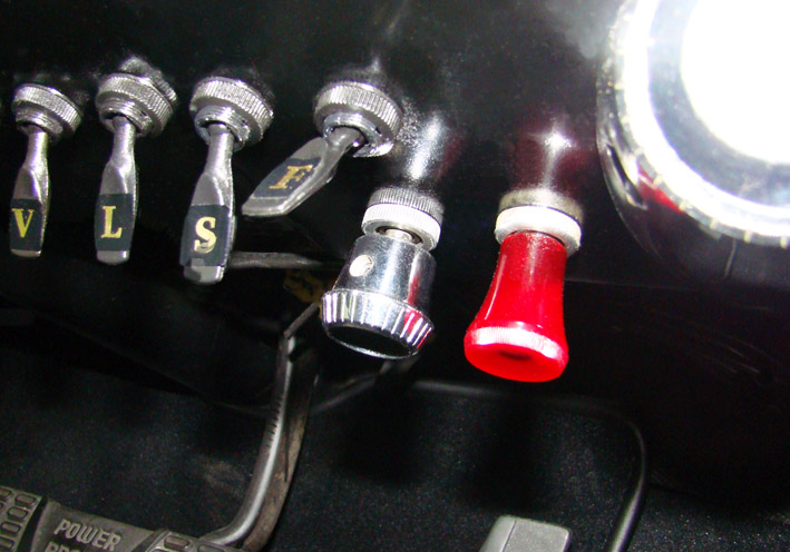 (01 Clock Time Setting Knob.jpg) (01 Clock Time Setting Knob.jpg)
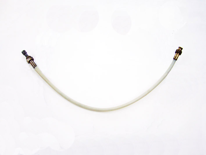 (02 Original Time Setting Cable.jpg) (02 Original Time Setting Cable.jpg)
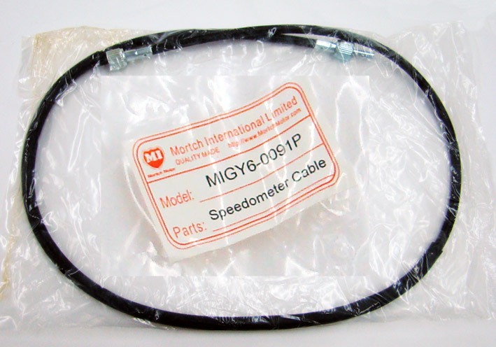 (03 Label Scooter Speedometer Cable.jpg) (03 Label Scooter Speedometer Cable.jpg)
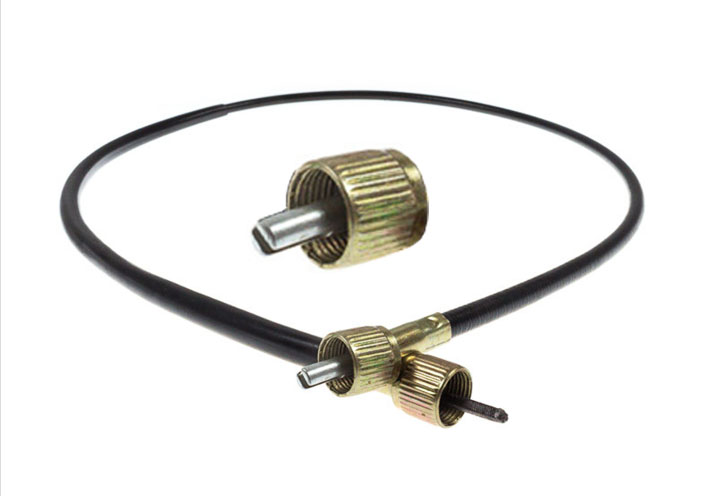 (04 Connections Scooter Speedometer Cable.jpg) (04 Connections Scooter Speedometer Cable.jpg)
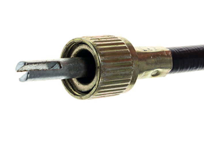 (05 Clockside Coupler.jpg) (05 Clockside Coupler.jpg)
 (06 Comparison Couplers Clockside.jpg) (06 Comparison Couplers Clockside.jpg)
 (07 Modifying Gap and Length of new Coupler.jpg) (07 Modifying Gap and Length of new Coupler.jpg)
 (08 Cutting both sides to the new Length.jpg) (08 Cutting both sides to the new Length.jpg)
 (09 Remove the Vinyl Tube by Heating.jpg) (09 Remove the Vinyl Tube by Heating.jpg)
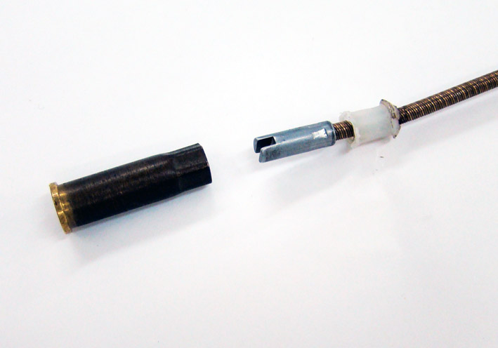 (10 Removed Broken Vinyl Tube.jpg) (10 Removed Broken Vinyl Tube.jpg)
 (11 Tinned Connector ready for Solder.jpg) (11 Tinned Connector ready for Solder.jpg)
 (12 Soldered Connector.jpg) (12 Soldered Connector.jpg)
 (13 Assembled Time Setting Cable.jpg) (13 Assembled Time Setting Cable.jpg)
 (14 Old and New Time Setting Cable.jpg) (14 Old and New Time Setting Cable.jpg)
Attachments
----------------
01 Clock Time Setting Knob.jpg (118KB - 745 downloads)
02 Original Time Setting Cable.jpg (31KB - 714 downloads)
03 Label Scooter Speedometer Cable.jpg (114KB - 687 downloads)
04 Connections Scooter Speedometer Cable.jpg (43KB - 710 downloads)
05 Clockside Coupler.jpg (48KB - 725 downloads)
06 Comparison Couplers Clockside.jpg (77KB - 692 downloads)
07 Modifying Gap and Length of new Coupler.jpg (85KB - 729 downloads)
08 Cutting both sides to the new Length.jpg (70KB - 706 downloads)
09 Remove the Vinyl Tube by Heating.jpg (71KB - 682 downloads)
10 Removed Broken Vinyl Tube.jpg (58KB - 689 downloads)
11 Tinned Connector ready for Solder.jpg (56KB - 726 downloads)
12 Soldered Connector.jpg (55KB - 715 downloads)
13 Assembled Time Setting Cable.jpg (79KB - 687 downloads)
14 Old and New Time Setting Cable.jpg (55KB - 707 downloads)
|
|
| |
|
Board Moderator & Exner Expert 10K+
Posts: 13062
Location: Southern Sweden - Sturkö island | It's nice to see the final result as you informed me about that you worked on this project Serge! Another "sergerized" improvement, thanks' for sharing this smart solution! |
|
| |
|
Elite Veteran
Posts: 1168
Location: D-70199 Heslach | 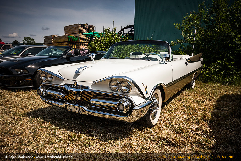 |
|
| |
|
Expert
Posts: 1215
Location: SWITZERLAND | Air-Deflector: The Air-Deflector under the dashboard distributes the incoming air from the center inlet to the left and right passenger side. It is made with a 1.5mm cardboard, therefore very sensitive to deformation, especially exposed when removing the radio. In my car this item was already badly damaged, and here out of function (01). Fixed with three screws it can easy be removed. From this a flat template could be reconstructed (02), and then modeled in 3D-CAD (03, 04). As material the backboard of a A4-scratchpad can be used, I found a thickness of 1.3mm that could simply be cut with a scissor (05). For a straight, edged ply use a bench vice, each side separate (05a). Painting in black to fit the surrounding and increasing the stiffness as well, after a distance check (100mm) the new Air-Deflector was ready to be mounted (06). Now the incoming air is redirected, as it should - another small and simple restoration (07). - SERGE - N.B. I didn’t removed the Air-Deflector when mounting back the Radio – first signs of “contacts” can already be seen! The Template in PDF, A4, 1:1, ready for direct print-out, is added (08).
Edited by sermey 2016-02-19 10:14 PM
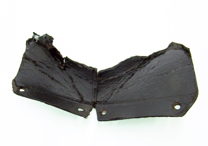 (01 Air-Deflector Damaged.jpg) (01 Air-Deflector Damaged.jpg)
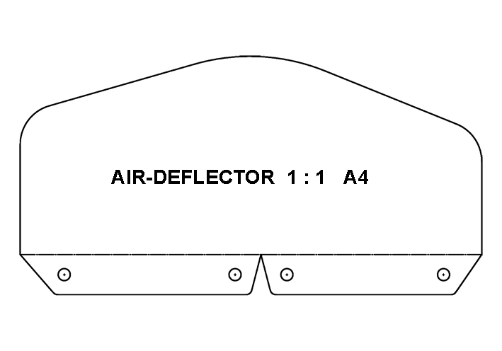 (02 Template Air Deflector Flat.jpg) (02 Template Air Deflector Flat.jpg)
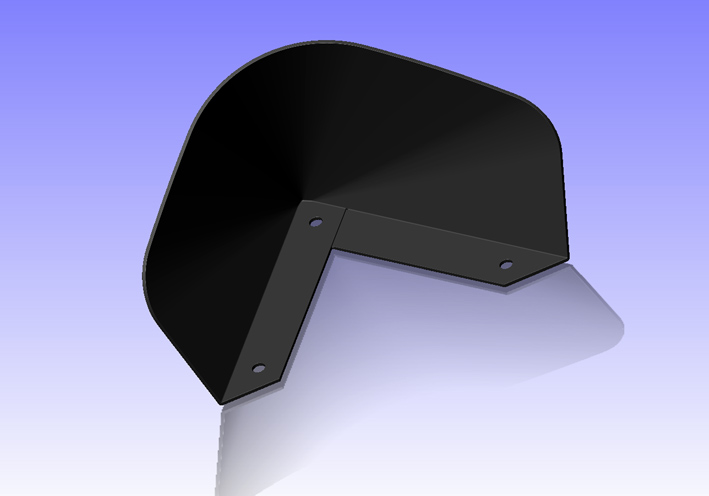 (03 Air Deflector FrontView CAD.jpg) (03 Air Deflector FrontView CAD.jpg)
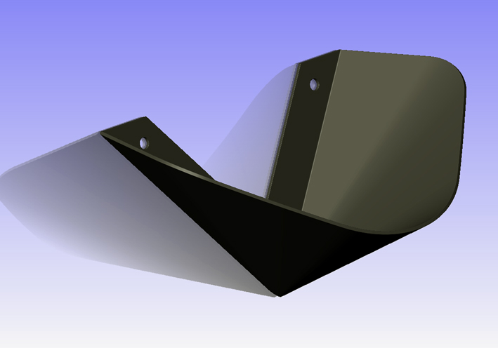 (04 Air Deflector SideView CAD.jpg) (04 Air Deflector SideView CAD.jpg)
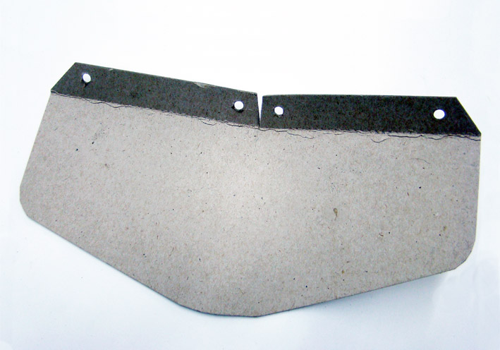 (05 Cut and Bent.jpg) (05 Cut and Bent.jpg)
 (05a Plying the Cardboard.jpg) (05a Plying the Cardboard.jpg)
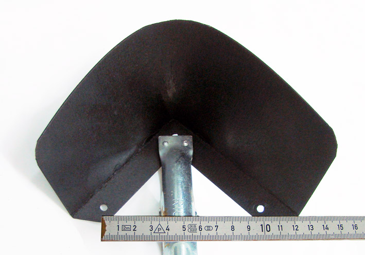 (06 Painted and Verifying Distance.jpg) (06 Painted and Verifying Distance.jpg)
 (07 New Air-Deflector Mounted.jpg) (07 New Air-Deflector Mounted.jpg)
Attachments
----------------
01 Air-Deflector Damaged.jpg (69KB - 651 downloads)
02 Template Air Deflector Flat.jpg (53KB - 668 downloads)
03 Air Deflector FrontView CAD.jpg (76KB - 652 downloads)
04 Air Deflector SideView CAD.jpg (113KB - 638 downloads)
05 Cut and Bent.jpg (94KB - 648 downloads)
05a Plying the Cardboard.jpg (83KB - 645 downloads)
06 Painted and Verifying Distance.jpg (94KB - 653 downloads)
07 New Air-Deflector Mounted.jpg (164KB - 648 downloads)
08 Template Air-Deflector A4-300dpi.pdf (78KB - 658 downloads)
|
|
| |
|
Expert
Posts: 1215
Location: SWITZERLAND | Speedometer 1: In the 1959 Dodge “the bar-type safety speedometer indicates green to 30 m.p.h., amber from 30 to 50 m.p.h., and red above 50 m.p.h.(Ross Roy)”. There are two different speedometer types, A and B. The second B has the additional option “speed warning signal” (01). Visually the two speedometers differ in various aspects as shown in direct comparison: Front Panel (02), Rear Panel (03), View Right Side (04), Different Covers (05) and Different Spring Systems (06). Due to the additional mechanics of the speed warning system, the drums (axes) and the glasses are not the same. Important to know is that the speed scales and the color bars on the drum are identical for both types (07). Pictures from my spare parts. (will be continued) - SERGE -
Edited by sermey 2016-02-23 5:54 PM
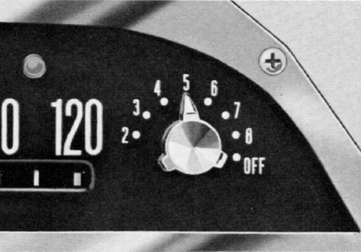 (01 Speed Warning Signal (Ross Roy).jpg) (01 Speed Warning Signal (Ross Roy).jpg)
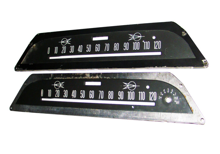 (02 Front Panel.jpg) (02 Front Panel.jpg)
 (03 Rear Panel.jpg) (03 Rear Panel.jpg)
 (04 View Right Side.jpg) (04 View Right Side.jpg)
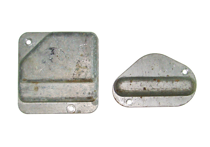 (05 Different Covers.jpg) (05 Different Covers.jpg)
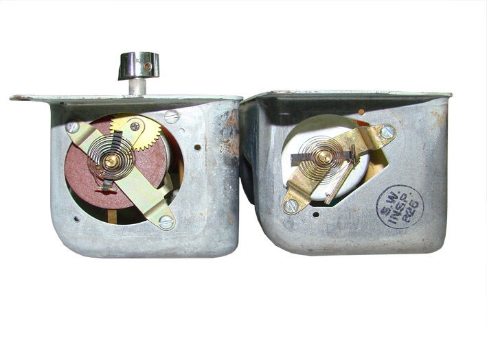 (06 Different Spring Systems.jpg) (06 Different Spring Systems.jpg)
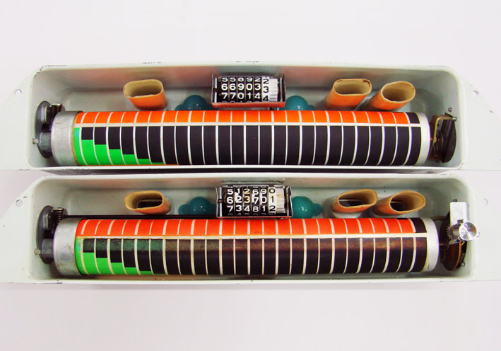 (07 View Inside - Identical Color Bars.jpg) (07 View Inside - Identical Color Bars.jpg)
Attachments
----------------
01 Speed Warning Signal (Ross Roy).jpg (110KB - 636 downloads)
02 Front Panel.jpg (87KB - 668 downloads)
03 Rear Panel.jpg (69KB - 694 downloads)
04 View Right Side.jpg (82KB - 648 downloads)
05 Different Covers.jpg (76KB - 671 downloads)
06 Different Spring Systems.jpg (87KB - 633 downloads)
07 View Inside - Identical Color Bars.jpg (110KB - 686 downloads)
|
|
| |
|
Expert
Posts: 1215
Location: SWITZERLAND | Speedometer 2: With age, humidity and light, the bar colors on the drum fade out and loose visibility – NOS replacement drums are very hard to find, when found it is mostly not the one you need (01). Easiest is to apply a new speedometer decal (02), preferable in thin resistive plastic. As the drum endings may vary, the decal must be aligned to the right side, and if needed cut on the left side (03). When the scale fits exactly to the original, no additional calibration is needed. Simply check with a BW Copy (04). In a CAD simulation the steps are illustrated (05) (06) (07), and the final result shown in (08) (09). A printable PDF-File is added , A4, 1 : 1, correct decal size 234.2 x 119mm (10). The colors may vary insignificantly depending of the used printer type. Verify the printed colors with the original and correct if needed. Now a new speedometer scale without disassembling and/or replacing the drum. - SERGE - Notice: Many printer reduce the size marginally, even when set at 100%. My A4 "BROTHER" has to be set at 100.5% to get print-out the exact width of 234.2mm (to be verified!).
Edited by sermey 2016-02-26 8:54 PM
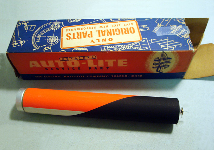 (01 NOS Auto-lite Drum.jpg) (01 NOS Auto-lite Drum.jpg)
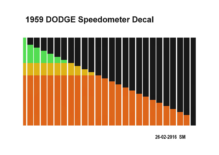 (02 1959 Dodge Speedometer Decal..jpg) (02 1959 Dodge Speedometer Decal..jpg)
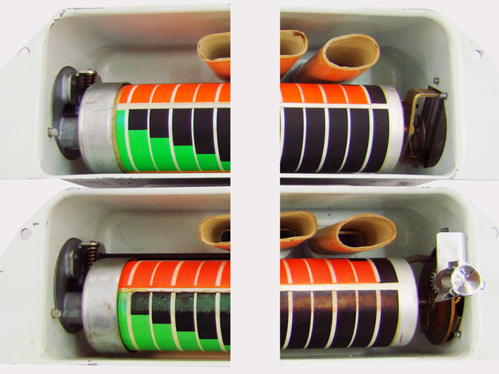 (03 Drum Ends Comparison.jpg) (03 Drum Ends Comparison.jpg)
 (04 Accuracy Check.jpg) (04 Accuracy Check.jpg)
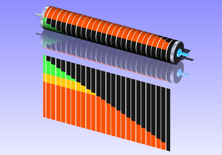 (05 Decal Ready CAD.jpg) (05 Decal Ready CAD.jpg)
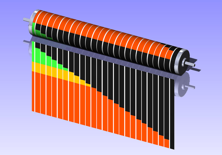 (06 Pre-Position Decal CAD.jpg) (06 Pre-Position Decal CAD.jpg)
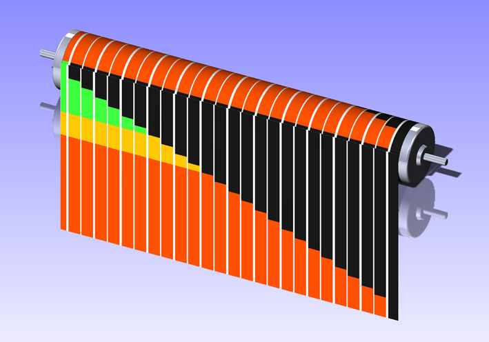 (07 Final Position Check CAD.jpg) (07 Final Position Check CAD.jpg)
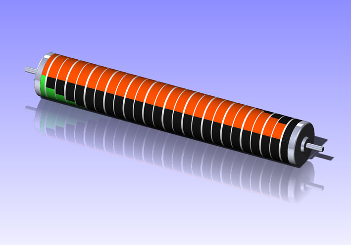 (08 Applied Decal Front Side CAD.jpg) (08 Applied Decal Front Side CAD.jpg)
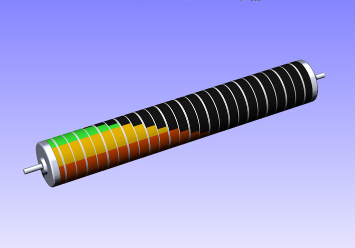 (09 Applied Decal Rear Side CAD.jpg) (09 Applied Decal Rear Side CAD.jpg)
Attachments
----------------
01 NOS Auto-lite Drum.jpg (125KB - 649 downloads)
02 1959 Dodge Speedometer Decal..jpg (105KB - 645 downloads)
03 Drum Ends Comparison.jpg (124KB - 678 downloads)
04 Accuracy Check.jpg (104KB - 650 downloads)
05 Decal Ready CAD.jpg (99KB - 647 downloads)
06 Pre-Position Decal CAD.jpg (98KB - 683 downloads)
07 Final Position Check CAD.jpg (101KB - 644 downloads)
08 Applied Decal Front Side CAD.jpg (67KB - 622 downloads)
09 Applied Decal Rear Side CAD.jpg (63KB - 644 downloads)
10 1959 Dodge Speedometer Decal A4.pdf (77KB - 646 downloads)
|
|
| |
|
Expert
Posts: 1215
Location: SWITZERLAND | Speedometer 3: The speedometer bar should show zero when the car is not moving, then it is adjusted correctly. When the green bar already shows an amount then the speedometer is mismatched as shown with the original drum (01), and similar with the new decal (02). Not showing any green at all, there is probably an under setting (03). The fine adjustment is done by removing the right cover, and shifting carefully the spring system with a pointy tool (04). For a secure and correct setting the initial green bar should preferably just be visible (05). Now the speedometer shows as it was the first day - SERGE -
Edited by sermey 2016-02-27 10:28 AM
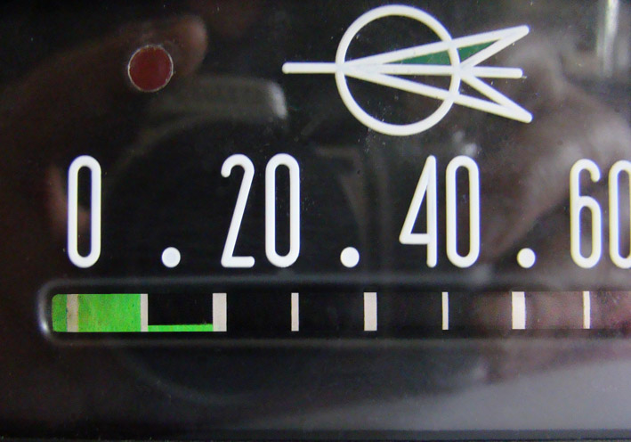 (01 Original Speedometer - Mismatched.jpg) (01 Original Speedometer - Mismatched.jpg)
 (02 New Speedometer - Mismatched.jpg) (02 New Speedometer - Mismatched.jpg)
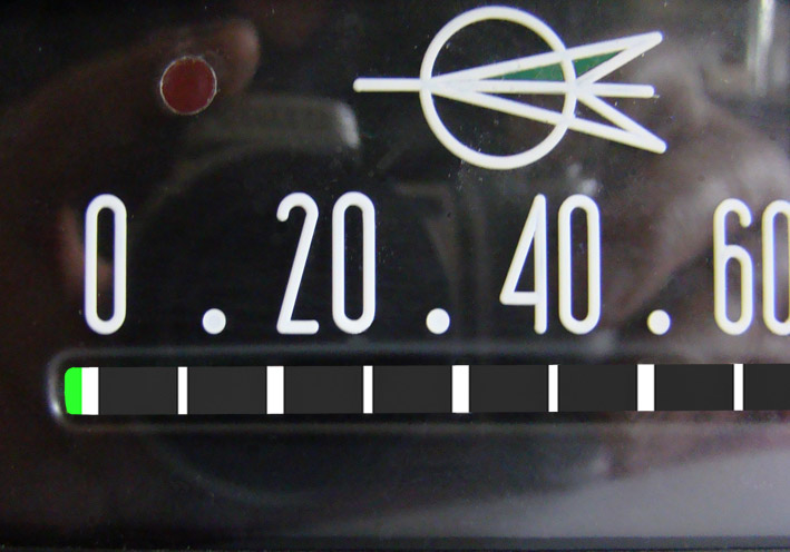 (03 New Speedometer - Zero Minus.jpg) (03 New Speedometer - Zero Minus.jpg)
 (04 Zero Adjustment.jpg) (04 Zero Adjustment.jpg)
 (05 New Speedometer - Zero Correct Setting.jpg) (05 New Speedometer - Zero Correct Setting.jpg)
Attachments
----------------
01 Original Speedometer - Mismatched.jpg (102KB - 636 downloads)
02 New Speedometer - Mismatched.jpg (99KB - 706 downloads)
03 New Speedometer - Zero Minus.jpg (98KB - 651 downloads)
04 Zero Adjustment.jpg (84KB - 647 downloads)
05 New Speedometer - Zero Correct Setting.jpg (98KB - 647 downloads)
|
|
| |
|
Elite Veteran
Posts: 781
Location: Montreal, Canada | Wow!!!
Thanks for the PDF. Great work as usual.
|
|
| |
|
Location: The Mile High City | Amazing and so detailed! Great work, Serge! |
|
| |
|
Expert
Posts: 1215
Location: SWITZERLAND | MOPAR Radio 856-857 with Audio Input: Even if the old Mopar Radio works perfectly, today this device is going to make no sense when the radio stations disappear, except as an eye-catcher in the car. There are high-tech conversions offered for FM-reception. These people do a nice job, as the radio keeps its full mechanical functionality. Meanwhile the DAB - Technology (Digital Audio Broadcast) is on the way and will soon replace the analog broadcasting systems (ABS), so as these modifications one day will become as well obsolete. To give the radio a “voice”, regardless of the source, an Audio Input is suggested. The original loudspeaker had already been replaced by a high power, wide-band type (01). The big high efficient magnet was grinded for just not touch the housing of the radio (02). It was obvious to have this loudspeaker driven by a power amplifier for lower impedance, and producing a higher output than the radio. I found a suitable Power Amplifier, direct operating up to 16VDC (03), with a cinch audio connection (04), that could be used for an Audio Input. From the cleaned schematic of the Mopar Radio 856,857 (05), here the resized section of the volume control unit (06). The Audio Input is done by “injecting” the sound source from earphone output of an external device (portable Radio, Cassette or CD-Player, SmartPhone), directly to the high end of the volume control A in red (07). This way the volume and the tone control of the radio is still remaining active, and the receiver operate as well. As the radio has a high impedance circuit, the audio input is decoupled by a serial resistor, minimum value 120k. The higher the value, the higher will be the attenuation of the applied input signal, but as well the lower the loading of the radio circuit. This adjustable Audio Input signal comes directly from the trimmer in the PowerAmp. The output B shown in green, comes from the tapper of the Volume Control, and leads with another 120k directly to the input of the PowerAmp. Means the inner connection of the input trimmer to the PowerCircuit has been previously cut. Note: To avoid possible hum, the two resistors 120k have to be soldered directly to the the volume control in the radio. These two wires, leading to the PowerAmp-In, are separately shielded. The 12V supply comes switched from the Radio, ground from the VC. The PowerAmp Unit has become a satellite of the radio (08). It is fixed inside the air deflector for direct access to the cinch input connector, and for easy adjustment of the audio sensitivity by the pre-set trimmer (09).While listening from audio input, the receiver is set to the end of the scale for no reception at all. Removing this system? Just cut all external cables and the radio will remain as it was before! But not forget to switch over the loudspeaker. Now the original car radio, together with the new built-in loudspeaker and a HiFi source, sounds even better as in the good old times. - SERGE - N.B. Separate the schematics in PDF.
Edited by sermey 2016-03-18 10:16 AM
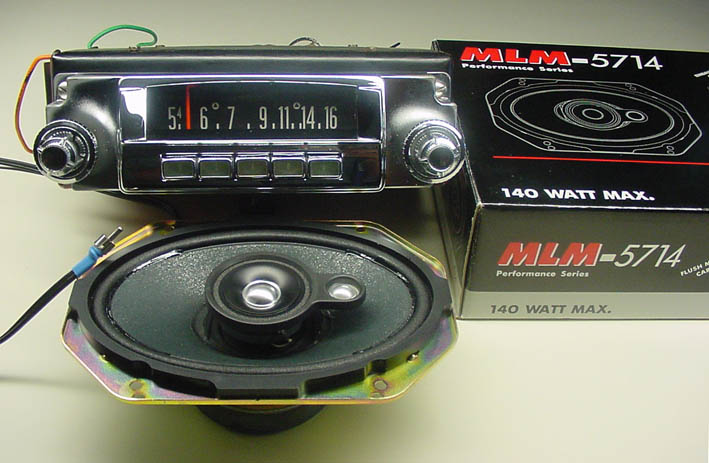 (01 MOPAR Radio 856-857.jpg) (01 MOPAR Radio 856-857.jpg)
 (02 Grinded Loudspeaker Magnet.jpg) (02 Grinded Loudspeaker Magnet.jpg)
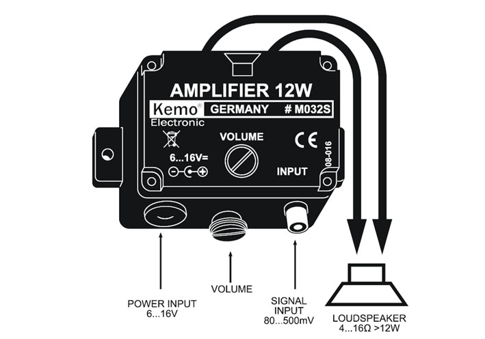 (03 KEMO Amplifier 12W M032S 25.jpg) (03 KEMO Amplifier 12W M032S 25.jpg)
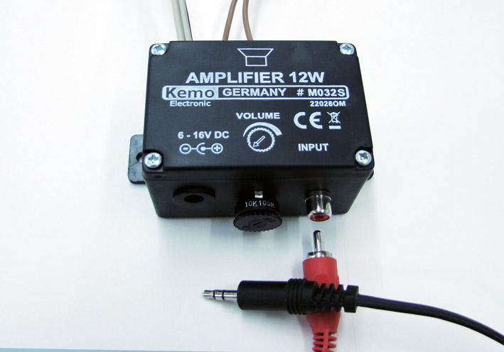 (04 PowerAmp Unit.jpg) (04 PowerAmp Unit.jpg)
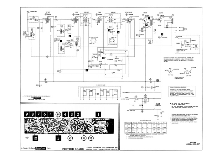 (05 Schematic Radio Mopar 856-857.jpg) (05 Schematic Radio Mopar 856-857.jpg)
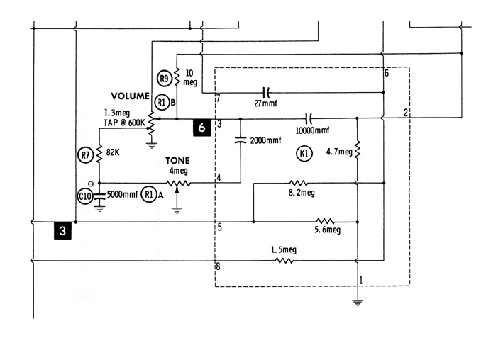 (06 Schematic Resized Section VC Unit.jpg) (06 Schematic Resized Section VC Unit.jpg)
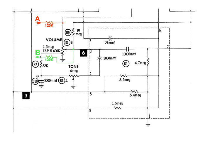 (07 Section VC with Audio Input A-Output B.jpg) (07 Section VC with Audio Input A-Output B.jpg)
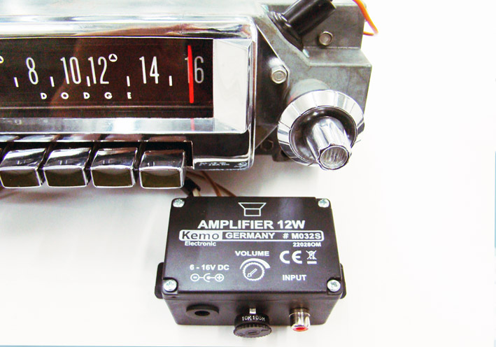 (08 MOPAR Radio with PowerAmp Unit.jpg) (08 MOPAR Radio with PowerAmp Unit.jpg)
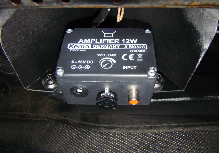 (09 View Mounted PowerAmp.jpg) (09 View Mounted PowerAmp.jpg)
Attachments
----------------
01 MOPAR Radio 856-857.jpg (82KB - 634 downloads)
02 Grinded Loudspeaker Magnet.jpg (90KB - 636 downloads)
03 KEMO Amplifier 12W M032S 25.jpg (74KB - 658 downloads)
04 PowerAmp Unit.jpg (79KB - 651 downloads)
05 Schematic Radio Mopar 856-857.jpg (114KB - 688 downloads)
06 Schematic Resized Section VC Unit.jpg (72KB - 653 downloads)
07 Section VC with Audio Input A-Output B.jpg (87KB - 655 downloads)
08 MOPAR Radio with PowerAmp Unit.jpg (112KB - 698 downloads)
09 View Mounted PowerAmp.jpg (90KB - 653 downloads)
Schematic Radio Mopar 856-857.pdf (197KB - 655 downloads)
Schematic Radio Mopar Section Volume Control.pdf (103KB - 660 downloads)
Schematic Radio Mopar VC Input A-Output B.pdf (107KB - 651 downloads)
|
|
| |
|
Expert
Posts: 1215
Location: SWITZERLAND | Horn Ring Pad 1: Years ago I purchased at the Big Meet in Vaesteras a NOS Steering Horn Ring without Pad (01). Back then I didn’t know that there are two different horn rings. The other one with pad and small golden knight (02) have been available in pad colors correspondingly to the car interior (03) (04) (05). These pads deforms and shrinks with time and are extreme rarely to find. From the used horn ring I purchased once, I could just use the small golden knight, temporarily mounted on the ashtray of my convertible. Recently I found a never used, NOS Horn Ring with green pad (06). All was perfect, except the pad was shrinked till 10mm at the end (07), partially deformed, the foam mostly rotted, and the metal insert widely detached due to long storage (08). The pad metal inserts, usually rusty and broken, could be cleaned (09) and inserted on the horn ring (10). By removed pad (11), the fixing gaps in the ring becomes visible (12). In case of needed replacement I have modeled this part on CAD (13). By laser cutting the stainless sheetmetall (0.5mm) according the flat metal insert (14), and then bending it around an axis 5 – 6 mm, this item can easily be reproduced (15). By one mirror command on CAD, the opposite sheet metal is done as well (16). Attached a printable PFD-File 1:1. The reproduction of this horn pad is firmly dedicated to the Swedish company RD Autoline (Tony), for they use the correct material as for Dash Pads, they know how to process quality foam, and fulfill a high technical standard. This here may be a contribution for a “start-up” . . . . . . - SERGE - :) (to be continued)
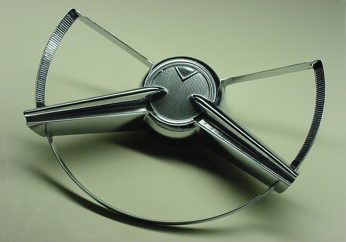 (01 NOS Steering Horn Ring without Pad.jpg) (01 NOS Steering Horn Ring without Pad.jpg)
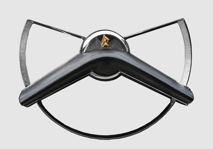 (02 Horn Ring with Black Pad.jpg) (02 Horn Ring with Black Pad.jpg)
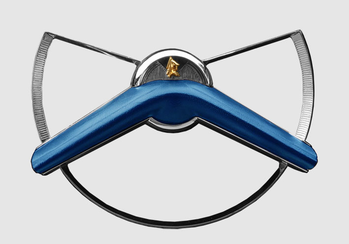 (03 Horn Ring with Blue Pad.jpg) (03 Horn Ring with Blue Pad.jpg)
 (04 Horn Ring with Green Pad.jpg) (04 Horn Ring with Green Pad.jpg)
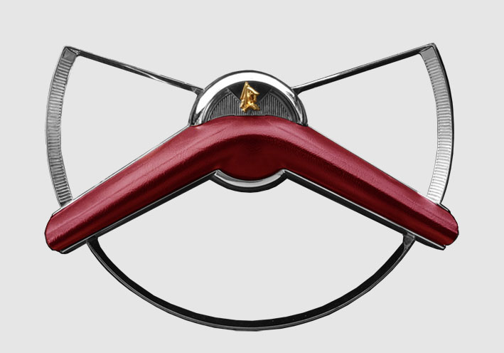 (05 Horn Ring with Red Pad.jpg) (05 Horn Ring with Red Pad.jpg)
 (06 NOS Horn Ring with Pad.jpg) (06 NOS Horn Ring with Pad.jpg)
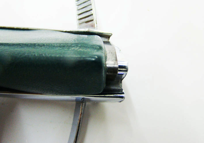 (07 Shrinked Horn Pad.jpg) (07 Shrinked Horn Pad.jpg)
 (08 Deformed Pad Front & Rear View.jpg) (08 Deformed Pad Front & Rear View.jpg)
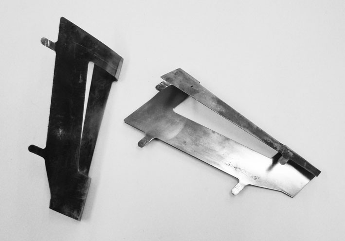 (09 Cleaned Horn Pad Metal Inserts.jpg) (09 Cleaned Horn Pad Metal Inserts.jpg)
 (10 Pad Metal inserted on Horn Ring.jpg) (10 Pad Metal inserted on Horn Ring.jpg)
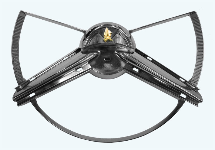 (11 Horn Ring Pad Removed.jpg) (11 Horn Ring Pad Removed.jpg)
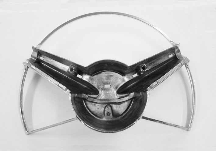 (12 Horn Ring Rear View.jpg) (12 Horn Ring Rear View.jpg)
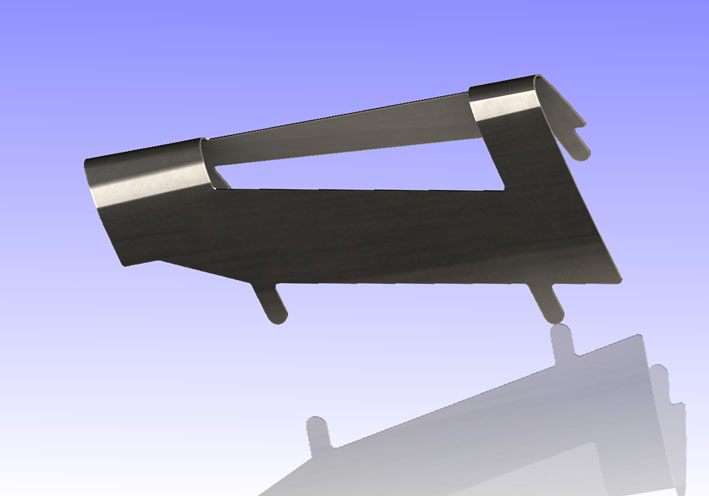 (13 Single Horn Pad Metal Insert CAD.jpg) (13 Single Horn Pad Metal Insert CAD.jpg)
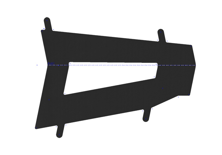 (14 Flat Horn Pad Metal Insert CAD.jpg) (14 Flat Horn Pad Metal Insert CAD.jpg)
 (15 Flattened Metal Insert CAD.jpg) (15 Flattened Metal Insert CAD.jpg)
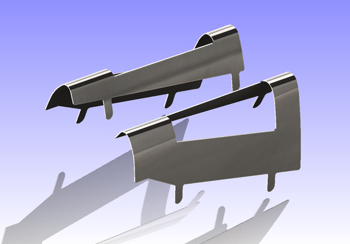 (16 Dual Horn Pad Metal Insert CAD.jpg) (16 Dual Horn Pad Metal Insert CAD.jpg)
Attachments
----------------
01 NOS Steering Horn Ring without Pad.jpg (82KB - 637 downloads)
02 Horn Ring with Black Pad.jpg (64KB - 641 downloads)
03 Horn Ring with Blue Pad.jpg (72KB - 640 downloads)
04 Horn Ring with Green Pad.jpg (65KB - 642 downloads)
05 Horn Ring with Red Pad.jpg (71KB - 645 downloads)
06 NOS Horn Ring with Pad.jpg (73KB - 666 downloads)
07 Shrinked Horn Pad.jpg (55KB - 638 downloads)
08 Deformed Pad Front & Rear View.jpg (79KB - 644 downloads)
09 Cleaned Horn Pad Metal Inserts.jpg (51KB - 638 downloads)
10 Pad Metal inserted on Horn Ring.jpg (73KB - 675 downloads)
11 Horn Ring Pad Removed.jpg (73KB - 661 downloads)
12 Horn Ring Rear View.jpg (59KB - 671 downloads)
13 Single Horn Pad Metal Insert CAD.jpg (42KB - 643 downloads)
14 Flat Horn Pad Metal Insert CAD.jpg (46KB - 650 downloads)
15 Flattened Metal Insert CAD.jpg (53KB - 677 downloads)
16 Dual Horn Pad Metal Insert CAD.jpg (51KB - 647 downloads)
Flat Horn Pad Metal Insert.pdf (103KB - 654 downloads)
|
|
| |
|
Expert
Posts: 1215
Location: SWITZERLAND | Remote Trunk Release 1: As there is no other way to open the trunk lid with a key, I let it mostly in the lock (01), sometimes even forget to remove it when driving. A remote trunk release would solve this situation. Many years ago I purchased a kit for an electric trunk release but could’nt find out a satisfying installation, for the lock is in the trunk lid. Animated by Jans (imopar380) clever solution, presented in this board . . .
http://www.forwardlook.net/forums/forums/thread-view.asp?tid=54494&posts=38&start=4 . . . I restarted this project involving this principle in a way that should be easy to reproduce. For the latch I used a flat aluminium profile 15mm x 2mm, first in CAD (02), then real in (03). A 8 x 0.85mm spring just fit in the lock housing: Bend one end and stretch the other side as shown (04). The axle is a M5 screw, the thread direct cut in the housing. Its drill position is adapted from the latch, so as nothing affect the key turn at all. The short slot assures additional track. By adding two washers as support under the latch, the M5 screw, all parts are ready for assembling (05): Insert the return spring in the 3mm hole, then turn it around out to be fixed. By turning out, the windings can be reduced for a higher return force (06). The other side just link in to the latch (07). Mount the M5 with the support washers and fix it with Loctite so as the latch can be moved easily. When activated, the stretched return spring becomes visible (08). The outer end will be cut when the activator is installed and tested (will be followed). Now the trunk lock unit is ready for remote activation (09). - SERGE - :) :)
Edited by sermey 2016-05-03 11:28 PM
 (01 Trunk Lid with Lock Key.jpg) (01 Trunk Lid with Lock Key.jpg)
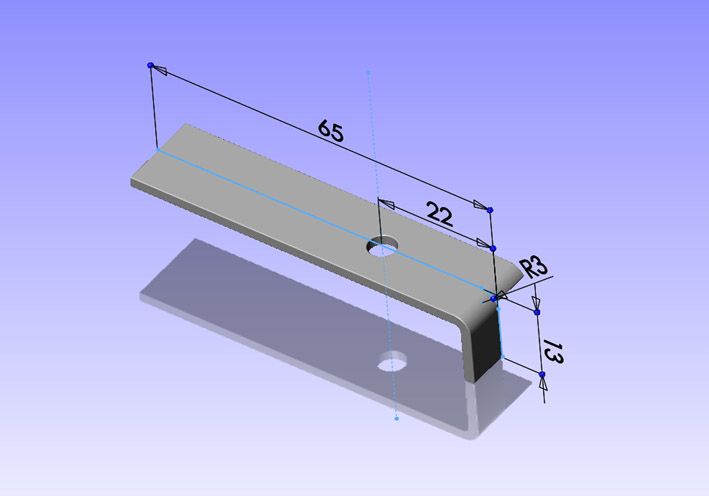 (02 Release Latch CAD.jpg) (02 Release Latch CAD.jpg)
 (03 Release Latch Alu-Profile.jpg) (03 Release Latch Alu-Profile.jpg)
 (04 Return Spring for Latch.jpg) (04 Return Spring for Latch.jpg)
 (05 Parts Ready for Assembling.jpg) (05 Parts Ready for Assembling.jpg)
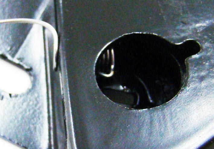 (06 Return Spring Inserted.jpg) (06 Return Spring Inserted.jpg)
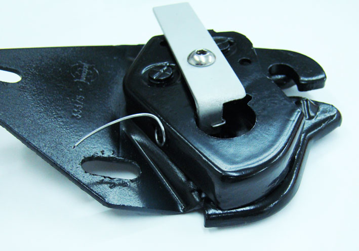 (07 Return Spring Mounted.jpg) (07 Return Spring Mounted.jpg)
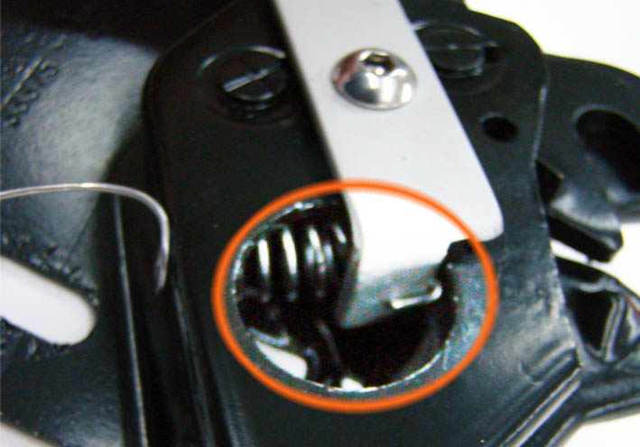 (08 Stretched Return Spring.jpg) (08 Stretched Return Spring.jpg)
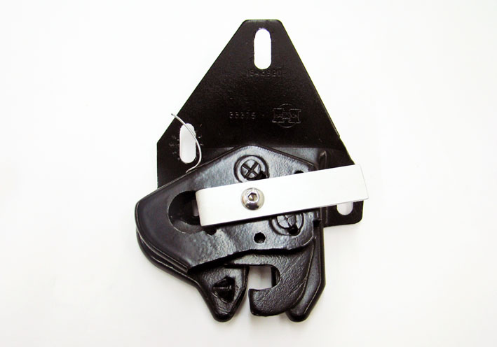 (09 Trunk Lock Ready for Remote.jpg) (09 Trunk Lock Ready for Remote.jpg)
Attachments
----------------
01 Trunk Lid with Lock Key.jpg (84KB - 682 downloads)
02 Release Latch CAD.jpg (56KB - 662 downloads)
03 Release Latch Alu-Profile.jpg (45KB - 675 downloads)
04 Return Spring for Latch.jpg (51KB - 658 downloads)
05 Parts Ready for Assembling.jpg (65KB - 655 downloads)
06 Return Spring Inserted.jpg (75KB - 680 downloads)
07 Return Spring Mounted.jpg (81KB - 650 downloads)
08 Stretched Return Spring.jpg (70KB - 653 downloads)
09 Trunk Lock Ready for Remote.jpg (53KB - 669 downloads)
|
|
| |
|
Expert
Posts: 1215
Location: SWITZERLAND | Remote Trunk Release 2 (mechanically): A mechanical trunk release can be activated at any time, as there is no need of a battery. The 1959 Dodge didn’t offered this option. Therefore it should be realized mostly invisible. It needs a release handle with return spring, for my car preferably in black, as found (01). Then a long control cable, as used for bikes (02). Tree of them (175cm) joined together using an alu-tube (5 x 4mm) glued with Cyanolit, over all a shrinking tube (03). The original core is replaced by a thinner, Nylon covered multistrand stainless wire, as already used for the remote mirror (04), for minimum return friction. If the wire cannot easy be pushed in through the length of 450cm, the friction is too high for the return spring mounted in the trunk lock. The wire ends are attached by a node, for the tensile force can reach up to 20kp. The front connection as illustrated in (05), and the rear connection by a crimped cable lug (06). The control cable starts from the release handle, fixed on the left side under the dashboard (07), leads under the sill plate (08) to the left hinge of the trunk lid (09). Here it is guided by a fixed rubber hose (10) for free movement. Then from inside the lid it ends through the lamp cavity to the trunk lock. The final length is adjusted by fixing the control cable with a latch, made with the same profile as used for the activation arm (11). For a horizontal position of this arm, preferably for the electric version (to come), the finger has been mirrored (12). Now the trunk can be manually opened as most actual cars, soft, comfortable and discreet (13). - SERGE - ;)
Edited by sermey 2016-06-12 3:08 AM
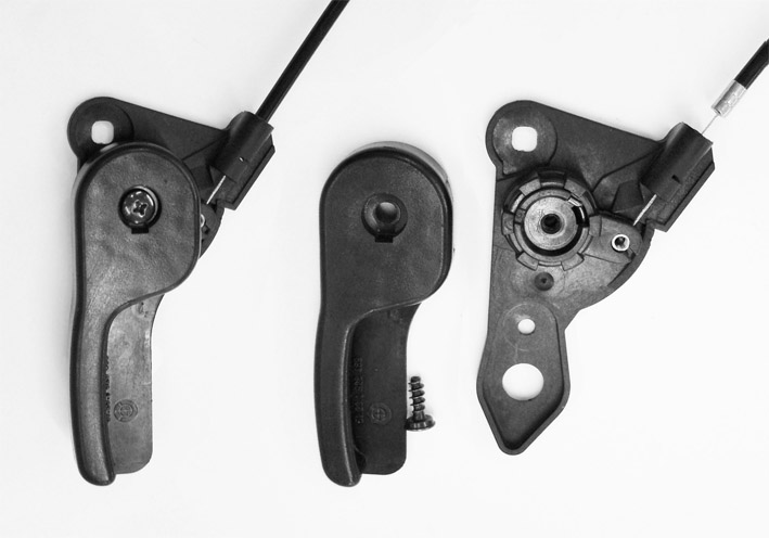 (01 Release Handle.jpg) (01 Release Handle.jpg)
 (02 Bike Shift Cable 175cm.jpg) (02 Bike Shift Cable 175cm.jpg)
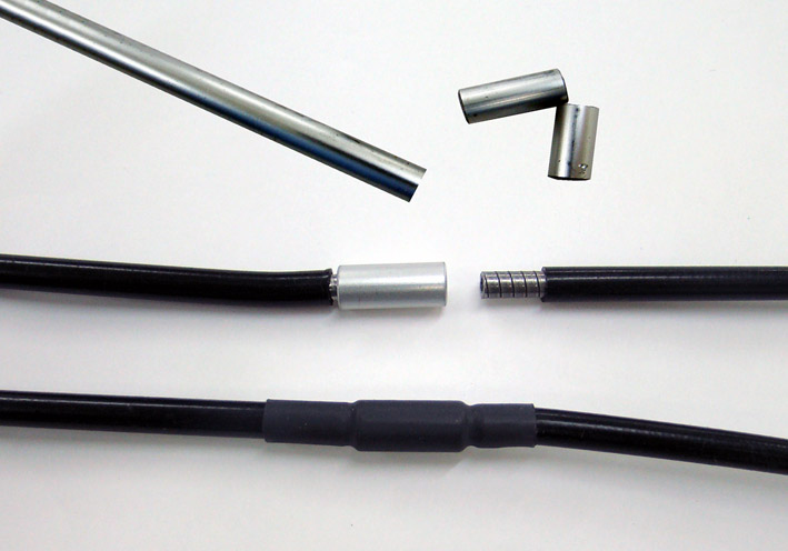 (03 Joined Cable.jpg) (03 Joined Cable.jpg)
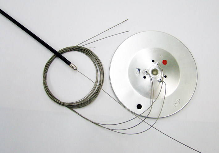 (04 Coated Multi Strand Stainless Wire.jpg) (04 Coated Multi Strand Stainless Wire.jpg)
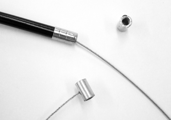 (05 Connection to Release Handle.jpg) (05 Connection to Release Handle.jpg)
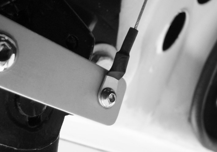 (06 Connection to Trunk Lock.jpg) (06 Connection to Trunk Lock.jpg)
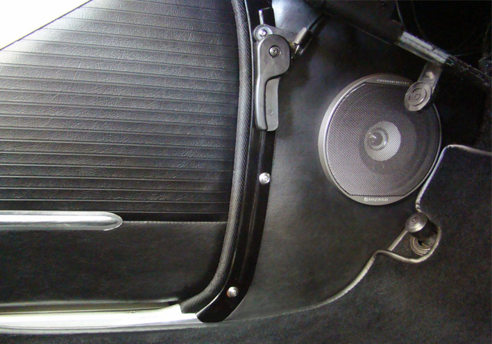 (07 Handle under the Dashboard.jpg) (07 Handle under the Dashboard.jpg)
 (08 Cable under the Sill Plate.jpg) (08 Cable under the Sill Plate.jpg)
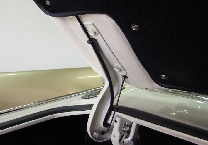 (09 Left Hinge of the Trunk Lid.jpg) (09 Left Hinge of the Trunk Lid.jpg)
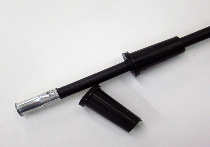 (10 Guide Rubber Hose.jpg) (10 Guide Rubber Hose.jpg)
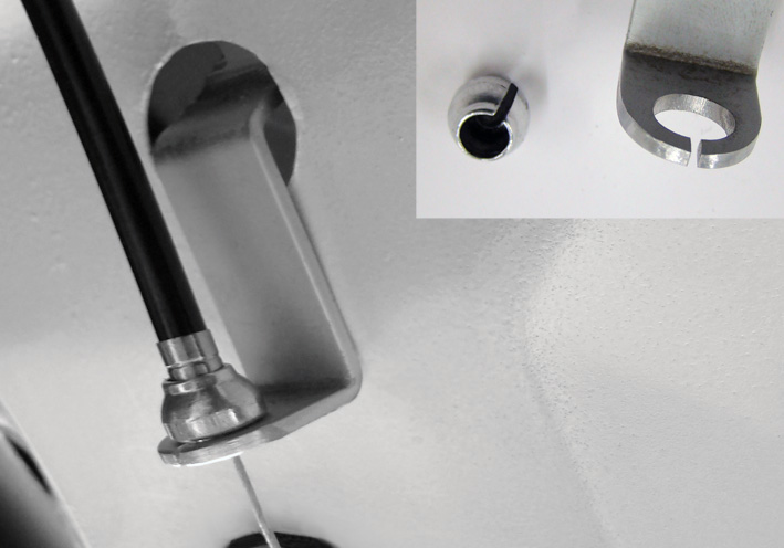 (11 Fixing the Operation Length.jpg) (11 Fixing the Operation Length.jpg)
 (12 Activation Arm Mirrored.jpg) (12 Activation Arm Mirrored.jpg)
 (13 Overview Lock Assembly.jpg) (13 Overview Lock Assembly.jpg)
Attachments
----------------
01 Release Handle.jpg (64KB - 607 downloads)
02 Bike Shift Cable 175cm.jpg (66KB - 608 downloads)
03 Joined Cable.jpg (72KB - 611 downloads)
04 Coated Multi Strand Stainless Wire.jpg (68KB - 585 downloads)
05 Connection to Release Handle.jpg (59KB - 570 downloads)
06 Connection to Trunk Lock.jpg (52KB - 589 downloads)
07 Handle under the Dashboard.jpg (105KB - 587 downloads)
08 Cable under the Sill Plate.jpg (74KB - 574 downloads)
09 Left Hinge of the Trunk Lid.jpg (85KB - 601 downloads)
10 Guide Rubber Hose.jpg (65KB - 582 downloads)
11 Fixing the Operation Length.jpg (88KB - 593 downloads)
12 Activation Arm Mirrored.jpg (39KB - 589 downloads)
13 Overview Lock Assembly.jpg (82KB - 599 downloads)
|
|
| |
|
Expert
Posts: 1215
Location: SWITZERLAND | Passenger Seat Molding: Recently I found themissing molding for the passenger seat, shown as offered (01). After cleaning, the black paint was applied, when pre-dried removed on the surface (02), as I did earlier with other items. The seat adjuster switch was mounted with a bracket, I got from Jan Fridberg with all the Power Seat Unit, years ago. This bracket fits exactly to the sloped seat frame, keeping the switch horizontal – as usual a nice job he did here! (03) For lack of another bracket an easy way to fix the passenger seat molding was needed. I used two bolts (M5) at fitted length. The one drilled on the correct position, for the other needing a standard bracket (04). This as well for the driver side in order to keep both moldings at the same distance. (05). The final position is given by the edge of the seat frame (06), furthermore both moldings should be parallel to the sill plate (07). Now these bezels protect the fragile plastic edge from being broken by careless rear passengers. Additional they express an optical upgrade (08). I have read that the 1959 Dodge is the car with most chrome at that time. From now I am near to believe it! - SERGE - :laugh:
Edited by sermey 2016-12-21 9:58 AM
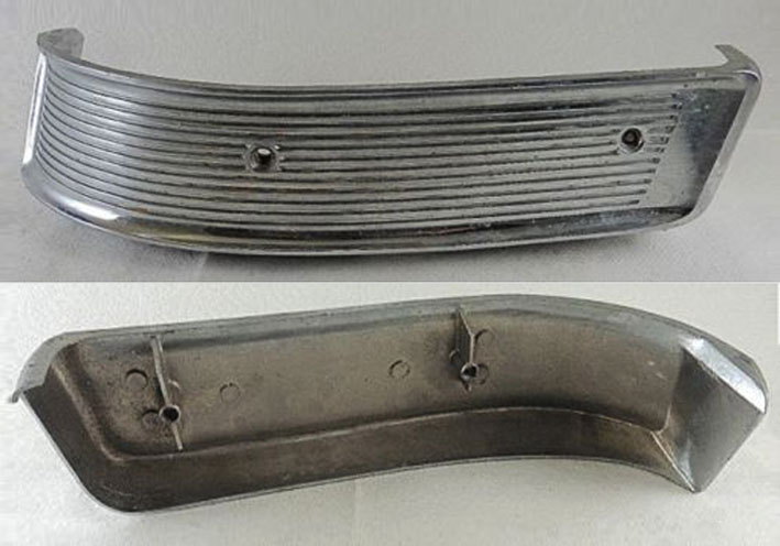 (01 Original As Offered.jpg) (01 Original As Offered.jpg)
 (02 Black Painted.jpg) (02 Black Painted.jpg)
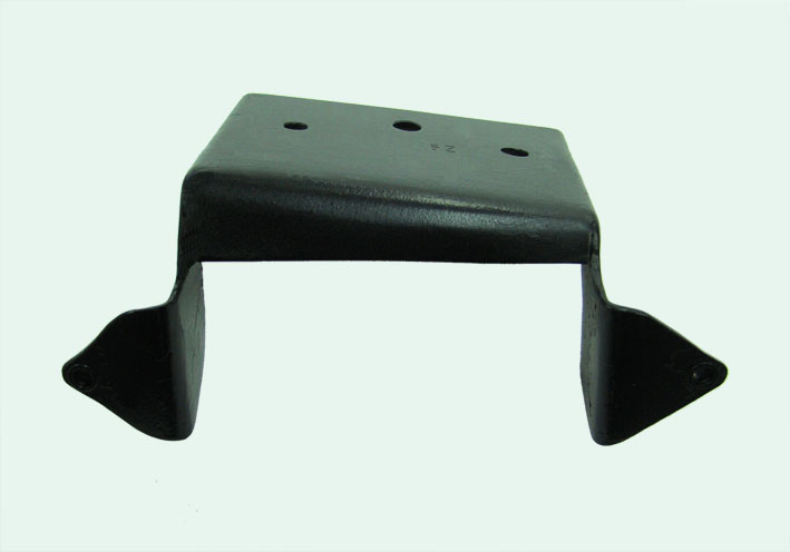 (03 Mounting Bracket.jpg) (03 Mounting Bracket.jpg)
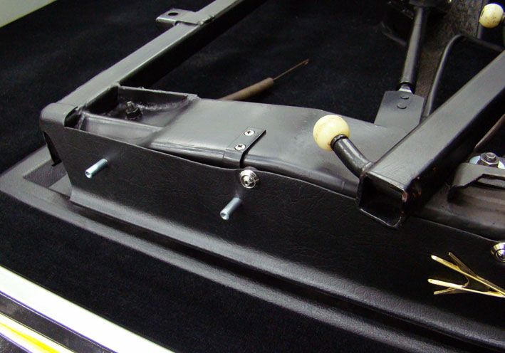 (04 Mounting Bolts.jpg) (04 Mounting Bolts.jpg)
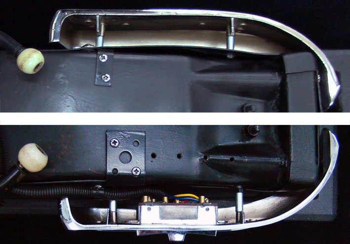 (05 Comparison.jpg) (05 Comparison.jpg)
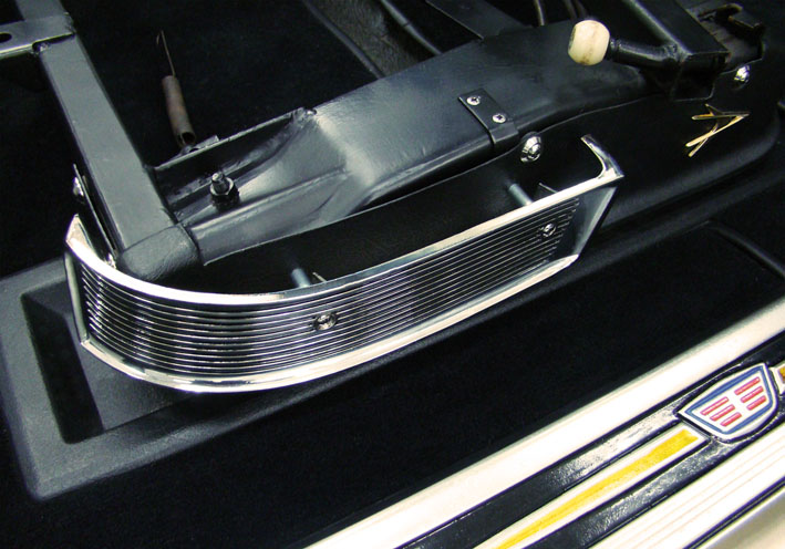 (06 Chrome Bezel Mounted.jpg) (06 Chrome Bezel Mounted.jpg)
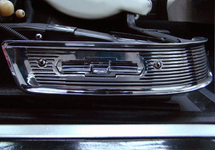 (07 Switch Bezel.jpg) (07 Switch Bezel.jpg)
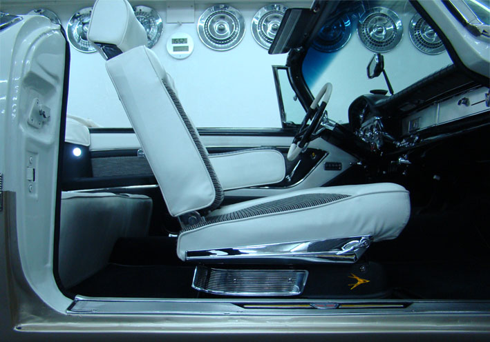 (08 Passenger Seat Side View.jpg) (08 Passenger Seat Side View.jpg)
Attachments
----------------
01 Original As Offered.jpg (70KB - 523 downloads)
02 Black Painted.jpg (80KB - 524 downloads)
03 Mounting Bracket.jpg (41KB - 528 downloads)
04 Mounting Bolts.jpg (100KB - 526 downloads)
05 Comparison.jpg (94KB - 519 downloads)
06 Chrome Bezel Mounted.jpg (111KB - 506 downloads)
07 Switch Bezel.jpg (87KB - 523 downloads)
08 Passenger Seat Side View.jpg (102KB - 511 downloads)
|
|
| |
|
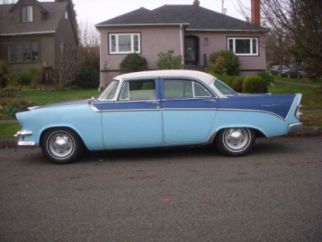
Exner Expert 10K+
Posts: 10042
Location: Lower Mainland BC | Just found this thread. Not sure if I should cheer or cry. The attention to detail is incredible. I will never be able achieve that on my car. But at least I have a (high) standard to strive for.
|
|
| |
|
Expert
Posts: 1215
Location: SWITZERLAND | (56D500boy) Just found this thread . . . . Thank you Dave for your kind comment. Doing things mostly at best, then everyone will get better results. But never think "I will never be able achieve . . ", then you stop yourself. All are better then they believe to be! What I show in this thread, not must be the best way to do, but it is HOW I did it . . . and it works. - SERGE - |
|
| |
|
Expert
Posts: 1215
Location: SWITZERLAND | Dash Pad 2: In the meantime I got the new dash pad from RD Autoline Sweden. It arrived in a very safe and solid packaging, well wrapped with soft protection air foil (01). First I put it on the hood, to make an initial acquaintance to the car (  ) to be equipped (02). A short look at the materials surface: impeccable (03). ) to be equipped (02). A short look at the materials surface: impeccable (03). All adjacent items around the dash have been removed: instruments unit, push buttons unit, rear view mirror, speaker insert and all the retaining moldings. As I didn’t removed the lower front panels (right-hand under the pad), the extension of the pad along this line was fold and stuck, and the other borders cut according the geometrical conditions (04). The new dash pad now could be pushed on, fully to its final position (05). No preliminary apertures or holes have been made until now, and no glue was used, as the dash pad fitted like a glove. To start fix the lower retainer moldings (06), final assemble the lamp with LED and lense (07). Then the right side molding (08), and on the left side the Push Buttons Unit (09). Now the dash pad is fixed cannot be moved forward anymore. The further proceeding will be reported in Dash Pad 3 to come. - SERGE -
Edited by sermey 2016-12-23 8:25 AM
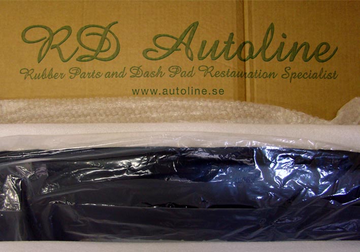 (01 Dash Pad Packaging 25.jpg) (01 Dash Pad Packaging 25.jpg)
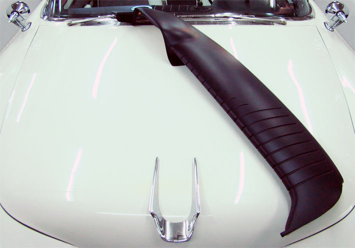 (02 Dash Pad on Hood 25.jpg) (02 Dash Pad on Hood 25.jpg)
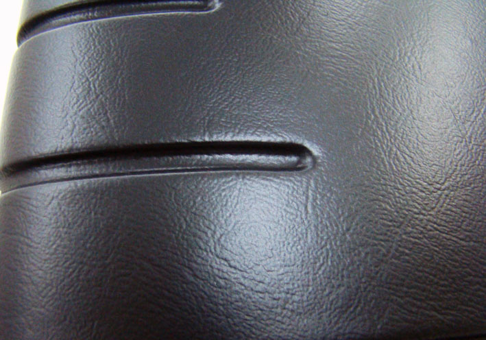 (03 Homogenous Material 25.jpg) (03 Homogenous Material 25.jpg)
 (04 Borders Modifications 25.jpg) (04 Borders Modifications 25.jpg)
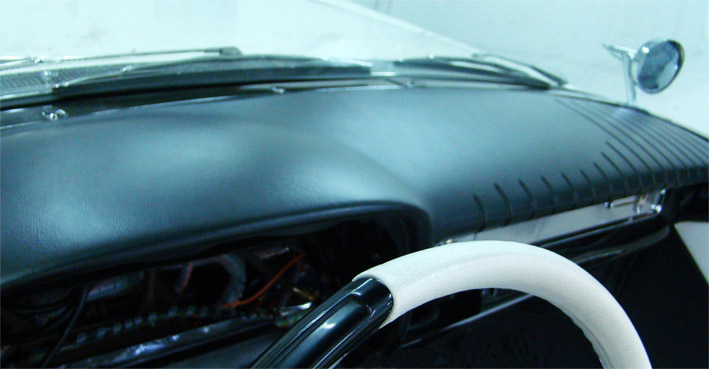 (05 Dash Pad pushed on 25.jpg) (05 Dash Pad pushed on 25.jpg)
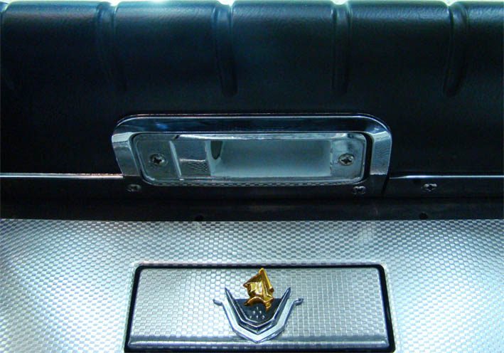 (06 Lower Moldings Mounted 25.jpg) (06 Lower Moldings Mounted 25.jpg)
 (07 Lamp with LED 25.jpg) (07 Lamp with LED 25.jpg)
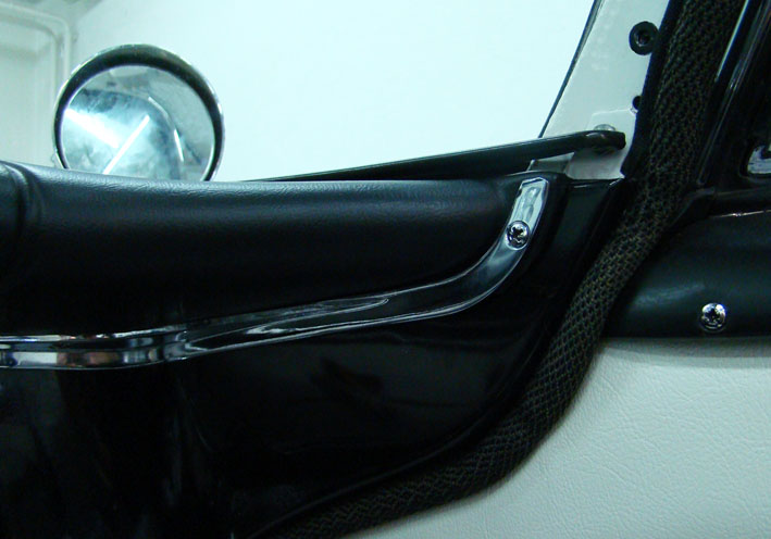 (08 Right Side Molding 25.jpg) (08 Right Side Molding 25.jpg)
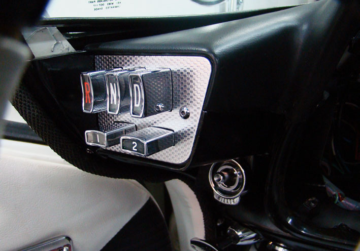 (09 Push Buttons Unit on Left Side 25.jpg) (09 Push Buttons Unit on Left Side 25.jpg)
Attachments
----------------
01 Dash Pad Packaging 25.jpg (78KB - 467 downloads)
02 Dash Pad on Hood 25.jpg (71KB - 471 downloads)
03 Homogenous Material 25.jpg (108KB - 475 downloads)
04 Borders Modifications 25.jpg (68KB - 462 downloads)
05 Dash Pad pushed on 25.jpg (84KB - 463 downloads)
06 Lower Moldings Mounted 25.jpg (90KB - 476 downloads)
07 Lamp with LED 25.jpg (91KB - 477 downloads)
08 Right Side Molding 25.jpg (72KB - 480 downloads)
09 Push Buttons Unit on Left Side 25.jpg (87KB - 463 downloads)
|
|
| |
|
Expert
Posts: 1215
Location: SWITZERLAND | Brake Switch: The brake pedal has to be depressed somewhat to activate the brake lights. In to-days car a small “touch” is sufficient. There are many interesting threads showing how to encounter this behavior by mounting a mechanical switch, in replacing the one on the master cylinder, solutions done in various and superior ways. Here I show a similar, but simpler way for the same target: I used an industrial switch with wheel (01), then added a distance bolt M5 x 40mm so as the switch assembly was ready for mount (02). Then drilled a hole at the right place, one screw and the switch was mounted (03). On the master cylinder I left all as it is, but added in parallel the supplemental cables (04). Now a small tip on the brake pedal, and the rear driver is alerted in better time. - SERGE -
Edited by sermey 2017-02-21 9:46 AM
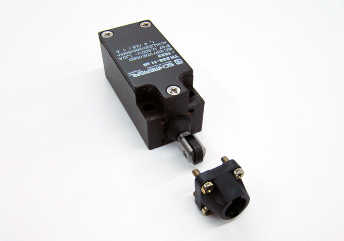 (01 Switch with Wheel.jpg) (01 Switch with Wheel.jpg)
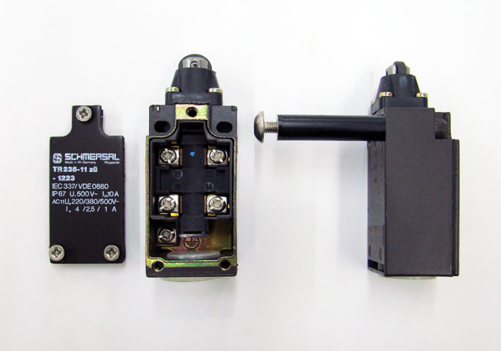 (02 New Switch Ready for Mount.jpg) (02 New Switch Ready for Mount.jpg)
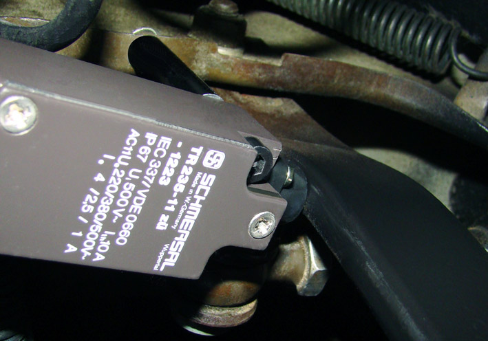 (03 New Brake Switch Mounted.jpg) (03 New Brake Switch Mounted.jpg)
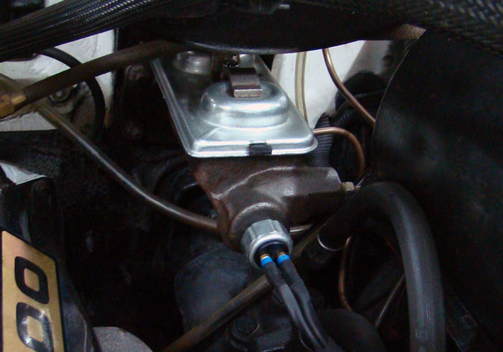 (04 Brake Switch of Master Cylinder.jpg) (04 Brake Switch of Master Cylinder.jpg)
Attachments
----------------
01 Switch with Wheel.jpg (56KB - 461 downloads)
02 New Switch Ready for Mount.jpg (63KB - 477 downloads)
03 New Brake Switch Mounted.jpg (101KB - 475 downloads)
04 Brake Switch of Master Cylinder.jpg (91KB - 471 downloads)
|
|
| |
|
Expert
Posts: 1215
Location: SWITZERLAND | Dash Pad 3: Now the items on the dash pad can be mounted and will hold it down, not any glue at all. The speaker cover includes the mounted loudspeaker and the ventilator hoses, to be assembled before fixing (01). The cover is used to create the template for cutting the aperture, then centered and fixed with nails (02). As the borders to the cover are narrow, a high cutting precision is required (03). For easy access inside the dash board this unit will be mounted later. To fix the interior rear view mirror, here the MirrorMatic, there are solid items disposable, and a special tool is needed (04). The stand is already designed to fit the thickness of the pad, so as it can be tighten strongly (06). Then the dash board is slightly pressed down, as it should be (07). The high flexible cable of the MirrorMatic, leaded through the stand, will be unvisible (08). Other for fix the Socket of the Automatic Beamer. Now it need longer screws, and to avoid squeezing the board additional distances (09). For fine tuning the direction of the sensor lens, I used finally wing nuts (10). Not forget to mount the front panel chrome bar. Instead of rusty clips as well stainless screws (11).
The further proceeding will be reported in Dash Pad 4 to come. - SERGE - :)
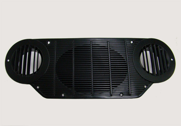 (01 Speaker Cover Black painted.jpg) (01 Speaker Cover Black painted.jpg)
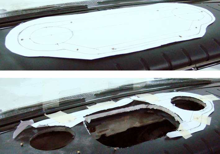 (02 Speaker Cover Template Fixed.jpg) (02 Speaker Cover Template Fixed.jpg)
 (03 Speaker Cover Dash Board Cut.jpg) (03 Speaker Cover Dash Board Cut.jpg)
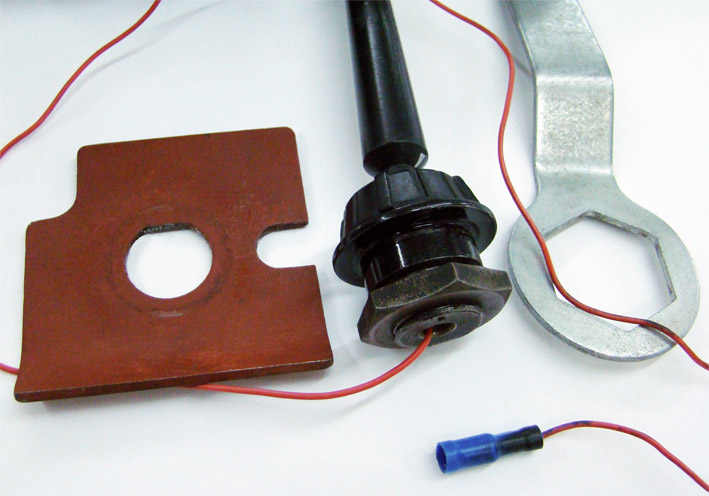 (04 Mirror Mounting items.jpg) (04 Mirror Mounting items.jpg)
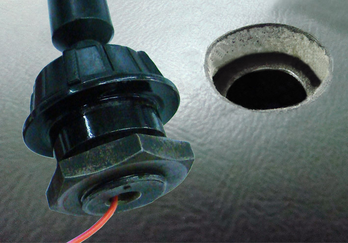 (05 Mirror Socket & Hole.jpg) (05 Mirror Socket & Hole.jpg)
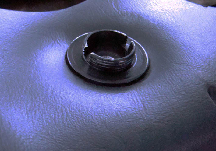 (06 Mirror Socket Mounted.jpg) (06 Mirror Socket Mounted.jpg)
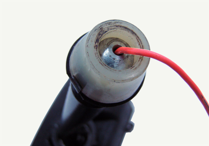 (07 Mirror Cable Outlet.jpg) (07 Mirror Cable Outlet.jpg)
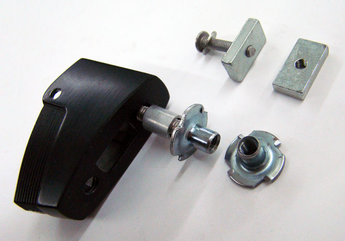 (08 Automatic Beamer Mounting Items.jpg) (08 Automatic Beamer Mounting Items.jpg)
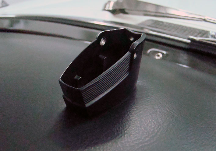 (09 Automatic Beamer Socket Mounted.jpg) (09 Automatic Beamer Socket Mounted.jpg)
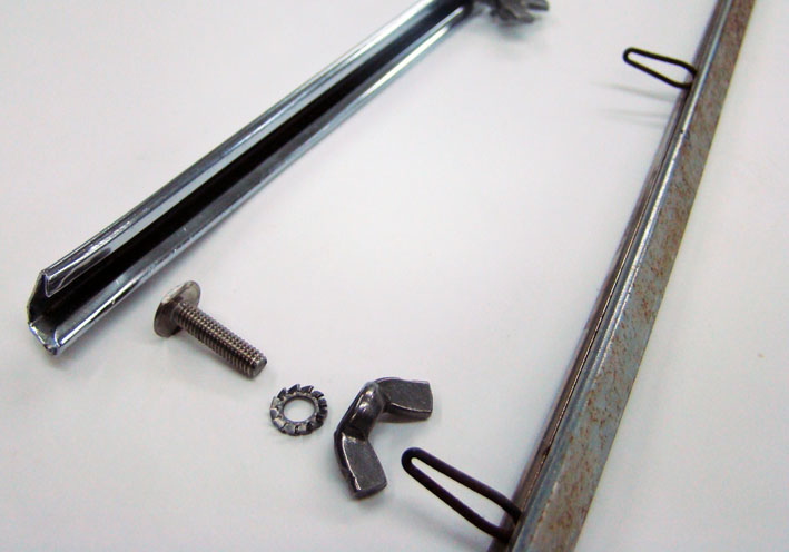 (10 Front Panel Chrome Bar.jpg) (10 Front Panel Chrome Bar.jpg)
Attachments
----------------
01 Speaker Cover Black painted.jpg (71KB - 460 downloads)
02 Speaker Cover Template Fixed.jpg (79KB - 453 downloads)
03 Speaker Cover Dash Board Cut.jpg (83KB - 463 downloads)
04 Mirror Mounting items.jpg (99KB - 482 downloads)
05 Mirror Socket & Hole.jpg (118KB - 474 downloads)
06 Mirror Socket Mounted.jpg (73KB - 460 downloads)
07 Mirror Cable Outlet.jpg (66KB - 473 downloads)
08 Automatic Beamer Mounting Items.jpg (66KB - 459 downloads)
09 Automatic Beamer Socket Mounted.jpg (75KB - 466 downloads)
10 Front Panel Chrome Bar.jpg (68KB - 467 downloads)
|
|
| |
|
Expert
Posts: 1215
Location: SWITZERLAND | Taillight Lenses: As NOS they are offered in various boxes (01) and labels (GLO-BRITE – SER-DO-TMC). When light ON they show visible differences in the red tone side on side (02), here OFF. Thus I have never bought a single one, but a complete set of four. Mounting NOS taillight lenses can be very critical. As their material has become brittle due to age, by inserting the first time the conical self-tapping screws, the lens may already brake. Further, as the original screws are shorter than the hole, when tighting the lenses threads may run out. Finally, the sealing rubber applies a constant pressure causing cold flow of the plastic material.Here how this can be prevented, shown for 1959 DODGE lenses: - Cut carefully a thread, preferably M4, for safety reasons using three screw taps (1-2-3), this to the full depth of the hole (03). - Insert a headless screw M4 and fix it with a glue without solvent (04). - Instead of standard rubbers (05) apply a permanent (never drying) flexible seal as used in sanitary (06).N Now the arranged lens is ready to be inserted in the housing (07). The screw will center the lens in the correct position, press in fully to the limit. The screw nuts slightly tightened, press in again till the stop is sensed, the seal is now fitted. For disassemble at removed nuts, wipe the lens softly, so as it can be pulled out. - SERGE - :)
Edited by sermey 2017-03-11 8:07 AM
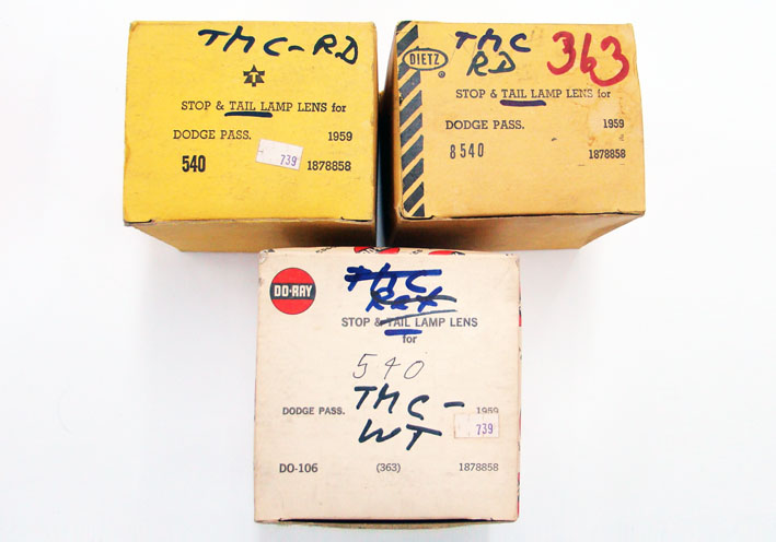 (01 Various Boxes.jpg) (01 Various Boxes.jpg)
 (02 Various Labels.jpg) (02 Various Labels.jpg)
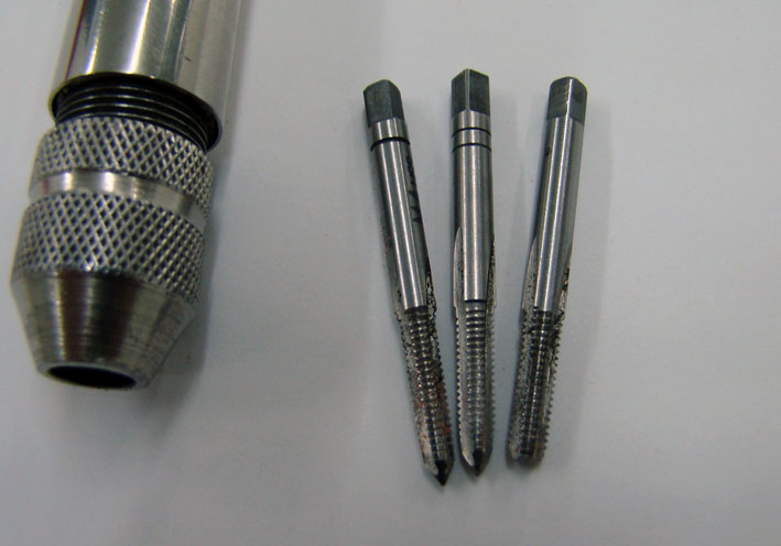 (03 Three Screw Taps.jpg) (03 Three Screw Taps.jpg)
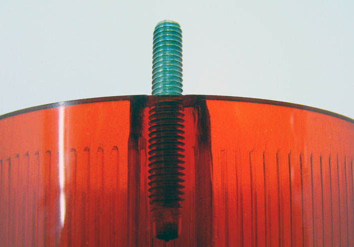 (04 Headless Screw Mounted.jpg) (04 Headless Screw Mounted.jpg)
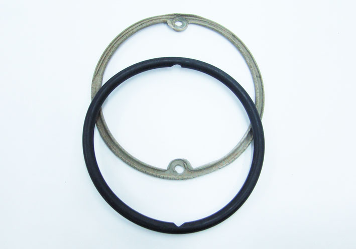 (05 Rubber Seals.jpg) (05 Rubber Seals.jpg)
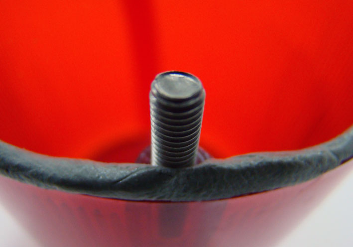 (06 Permanent Flexible Seal.jpg) (06 Permanent Flexible Seal.jpg)
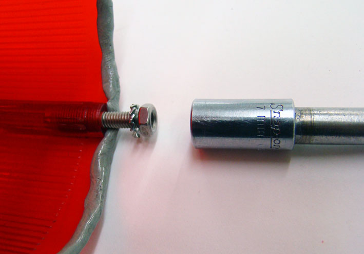 (07 Lens ready for mount.jpg) (07 Lens ready for mount.jpg)
Attachments
----------------
01 Various Boxes.jpg (71KB - 444 downloads)
02 Various Labels.jpg (75KB - 461 downloads)
03 Three Screw Taps.jpg (63KB - 461 downloads)
04 Headless Screw Mounted.jpg (62KB - 457 downloads)
05 Rubber Seals.jpg (43KB - 450 downloads)
06 Permanent Flexible Seal.jpg (51KB - 455 downloads)
07 Lens ready for mount.jpg (51KB - 450 downloads)
|
|
| |
|
Elite Veteran
Posts: 1168
Location: D-70199 Heslach | Found on Fazzebook.
Sankt Margarethen 1999
 (1999 US-Car Meeting in St. Margrethen (CH) 001.jpg) (1999 US-Car Meeting in St. Margrethen (CH) 001.jpg)
Attachments
----------------
1999 US-Car Meeting in St. Margrethen (CH) 001.jpg (139KB - 452 downloads)
|
|
| |
|
Expert
Posts: 1215
Location: SWITZERLAND | Yes, I did Dave, as described earlier in this thread. - SERGE - |
|
| |
|
Expert
Posts: 1215
Location: SWITZERLAND | LED Headlights: First they had pressed glass lamps (01), not efficient and a somewhat yellow light. Later appeared the halogen beam bulbs, H4, H7, with whiter light (02). The newest blue bulb should produce a cooler light.H4 is a dual beam with two connectors, H7 single a beam with one connector. Standard in FWL-cars there are two single H7 and two dual H4 bulbs. Earlier I modified all pressed glass lamps to halogen H4, enabling to turn ON all 4 beams by a separate switch, for show or redundancy only (03).
Now the time has come to have really white headlights using LED technology. There are various devices on the market, some with built-in ventilator, and some without. As I don’t like something additional moving and noising, I preferred the LED beam bulb with a conventional heat sink module. As best for my purpose I found: Philips 9003 CSP H4 HB2 LED Car Headlight Hi/Lo Beam Bulbs 180W 18000LM 6500K (04). It has the same 3-pole connector as needed for my DODGE (and other FWL-Cars), enabling a direct connection (05). As this modification needs some special approaches, some steps are presented more detailed.
First the entire headlight unit has to be pulled out, fixed by the 3 screws, and the back panel removed (06). As there is not enough space for the connectors behind the bulb, due to the cooling module, they have to be transferred outside the beamer housing. Fortunately the cable length of the LED unit just fits, as well the depth for the cooling module, straight correct (5mm!). The original sealing rubber cannot be mounted as is, must cut and grind (07). A permanent (never-drying) flexible seal can be applied instead. Then the LED beamer has to be opened by unfasten the side screw (08), and unsolder the three wires (09). Inverse the rubber seal for mount (10), re-solder the wires, and fix the items as it was (11). Inverse again the rubber seal and spread the retainer springs for free positioning (12), and when LED Beamer is inserted fix it by clipping in (13), done (14). The rear lamp panel can be linked in (15), the entire LED headlight unit is ready for install (16). Now re-mount this Unit by the 3 fixing screws, then connect the LED bulb, and the new beamer system is ready for operate. As the bulb has two single LED arrays, the light emission with the reflector is according to the halogen bulb. This is a reference check (17). The earlier pressed glass lamps looked yellow in comparison to the halogen lamps. Now the halogen lamps seemed as well to shine quite yellow in comparison to the full white LED light (18). The improved lightning is impressive, for security, on road, at night – and for show (road pictures will be posted later on). Another useful and outstanding feature, adaptable for most FWL-cars! - SERGE - ;)
Edited by sermey 2017-03-14 2:59 AM
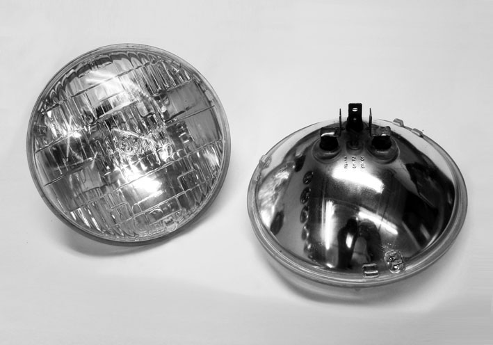 (01 Pressed Glass Lamp.jpg) (01 Pressed Glass Lamp.jpg)
 (02 Halogen Headlight Bulbs.jpg) (02 Halogen Headlight Bulbs.jpg)
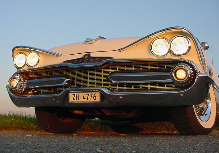 (03 All Halogen Headlights ON.jpg) (03 All Halogen Headlights ON.jpg)
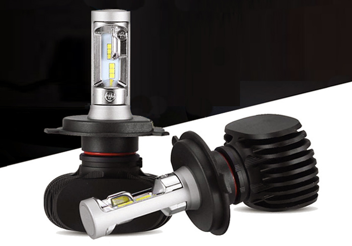 (04 LED Headlight H4 Philips CSP.jpg) (04 LED Headlight H4 Philips CSP.jpg)
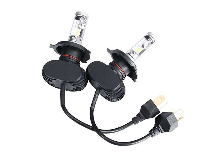 (05 H4 Headlights connectors.jpg) (05 H4 Headlights connectors.jpg)
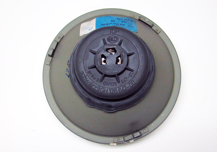 (06 Halogen Headlight Unit Rear View.jpg) (06 Halogen Headlight Unit Rear View.jpg)
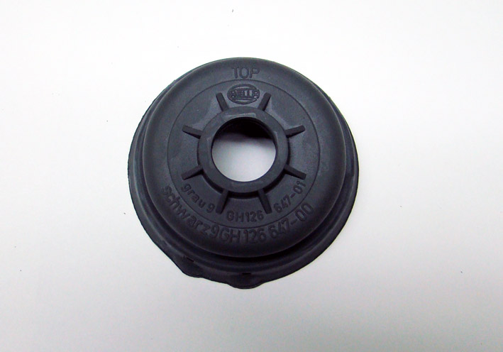 (07 Rubber Seal Diameter Cut and Grinded.jpg) (07 Rubber Seal Diameter Cut and Grinded.jpg)
 (08 Unfasten the Cooling Module.jpg) (08 Unfasten the Cooling Module.jpg)
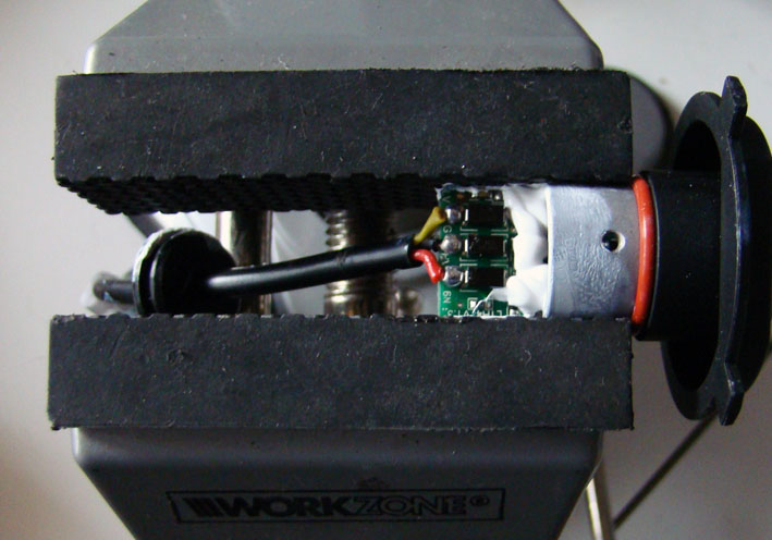 (09 Ready for unsolder.jpg) (09 Ready for unsolder.jpg)
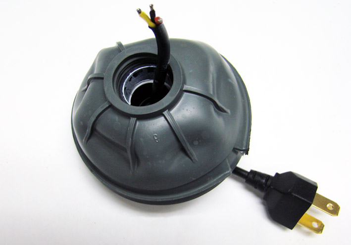 (10 Rubber inversed over Cooling Module.jpg) (10 Rubber inversed over Cooling Module.jpg)
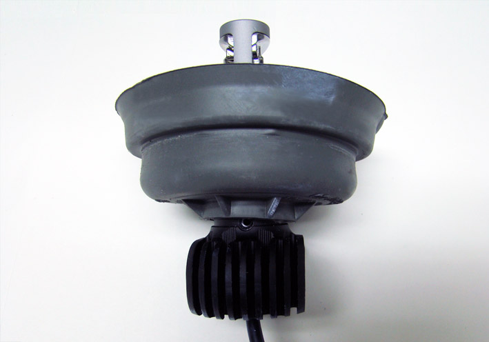 (11 Rubber back for fixing.jpg) (11 Rubber back for fixing.jpg)
 (12 Retainer Spring Spread.jpg) (12 Retainer Spring Spread.jpg)
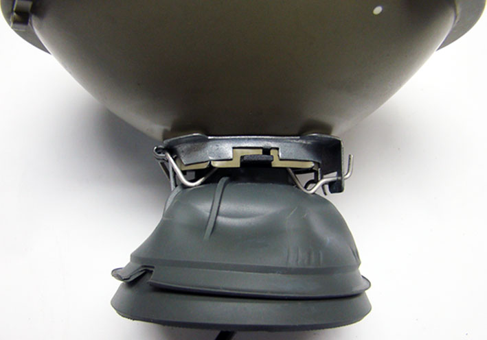 (13 LED Fixed with Retainer Spring.jpg) (13 LED Fixed with Retainer Spring.jpg)
 (14 LED Headlight Side View.jpg) (14 LED Headlight Side View.jpg)
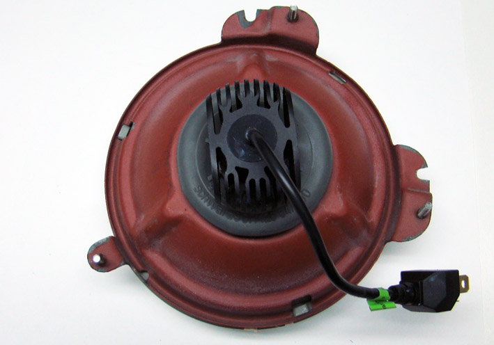 (15 LED Headlight Unit Ready for install.jpg) (15 LED Headlight Unit Ready for install.jpg)
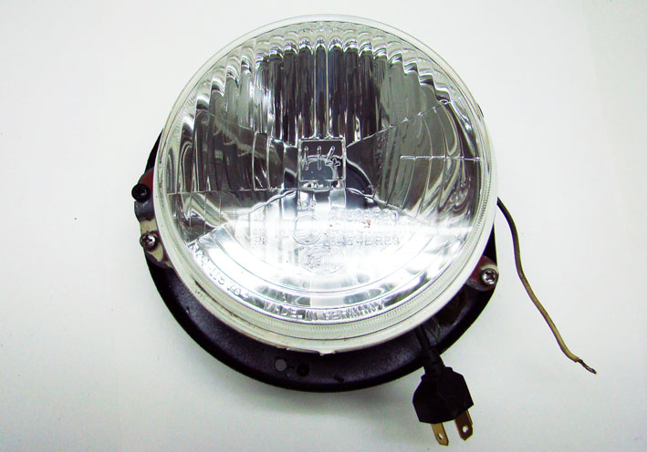 (16 LED Headlight Unit Front View.jpg) (16 LED Headlight Unit Front View.jpg)
 (17 LED Alignment Test.jpg) (17 LED Alignment Test.jpg)
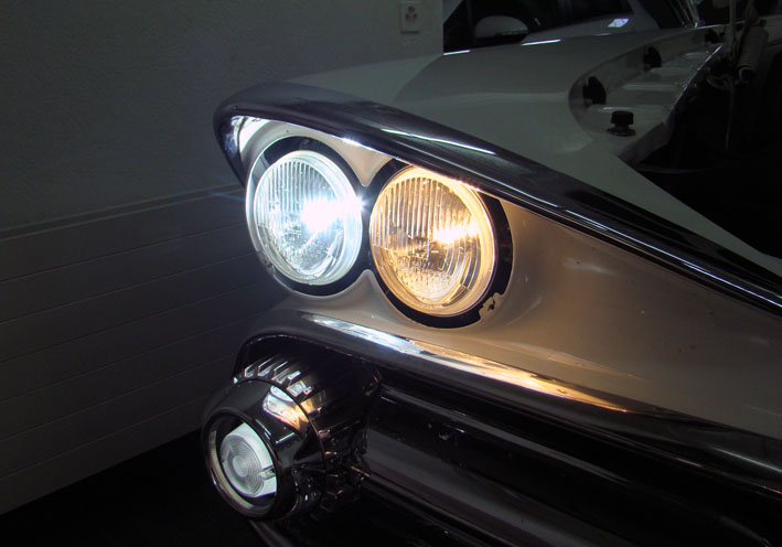 (18 Difference Halogen - LED Headlight.jpg) (18 Difference Halogen - LED Headlight.jpg)
Attachments
----------------
01 Pressed Glass Lamp.jpg (62KB - 524 downloads)
02 Halogen Headlight Bulbs.jpg (77KB - 544 downloads)
03 All Halogen Headlights ON.jpg (111KB - 523 downloads)
04 LED Headlight H4 Philips CSP.jpg (106KB - 526 downloads)
05 H4 Headlights connectors.jpg (68KB - 530 downloads)
06 Halogen Headlight Unit Rear View.jpg (80KB - 537 downloads)
07 Rubber Seal Diameter Cut and Grinded.jpg (70KB - 527 downloads)
08 Unfasten the Cooling Module.jpg (62KB - 521 downloads)
09 Ready for unsolder.jpg (89KB - 507 downloads)
10 Rubber inversed over Cooling Module.jpg (66KB - 537 downloads)
11 Rubber back for fixing.jpg (55KB - 553 downloads)
12 Retainer Spring Spread.jpg (81KB - 528 downloads)
13 LED Fixed with Retainer Spring.jpg (54KB - 538 downloads)
14 LED Headlight Side View.jpg (77KB - 534 downloads)
15 LED Headlight Unit Ready for install.jpg (81KB - 532 downloads)
16 LED Headlight Unit Front View.jpg (87KB - 527 downloads)
17 LED Alignment Test.jpg (51KB - 524 downloads)
18 Difference Halogen - LED Headlight.jpg (72KB - 511 downloads)
|
|
| |
|
Board Moderator & Exner Expert 10K+
Posts: 13062
Location: Southern Sweden - Sturkö island | Very nice "update" modification Serge. This is a safety and improved night driving option that anyone could install.
You have also chosen the correct quality LED's with the light elements in the same place as the filament in a bulb, which makes a perfect match and light beam alignment "as before".
Also, this is easy to remove if someone would like to go "hard-core purist" on a car!
Very nice background explanation and good photos - as usually |
|
| |
|
Expert
Posts: 1215
Location: SWITZERLAND | Circular LEDs: Replacing the standard bulbs of the taillights by LED lamps, the overall light has become significant brighter, but the difference in intensity between position light and stop/directional light got somewhat reduced. I found a circular red LED device (01), with a plastic carrier 60mm, fitted with a mini connector (02). Without the carrier it has an outer diameter of 59mm, fitting exactly in the inner groove of the taillight lens (03), being fixed with some glue. The cable is fed through the lamps housing (04), is connected separately, and can be disconnected at any time if needed, rear the lamp unit. When OFF, the LED is not noticeable from outside. This a view at reduced camera (05). (road pictures will be posted later on). Now the stop and directional light has become more accentuated - for the rear drivers highly spectacular (06)! - SERGE -
Edited by sermey 2017-03-15 12:51 PM
 (01 Circular Red LED.jpg) (01 Circular Red LED.jpg)
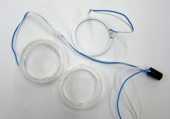 (02 LED with Carrier and Connector.jpg) (02 LED with Carrier and Connector.jpg)
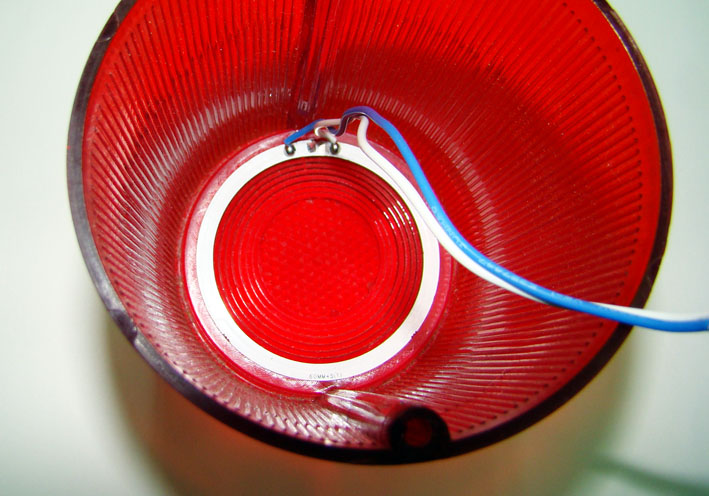 (03 Circular LED in Taillight Lens.jpg) (03 Circular LED in Taillight Lens.jpg)
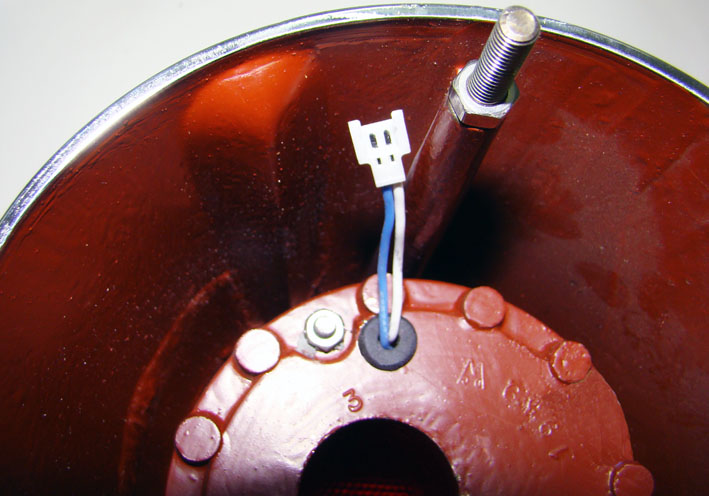 (04 DSC07835 Cable Feedthrough.jpg) (04 DSC07835 Cable Feedthrough.jpg)
 (05 Circular Red LED ON.jpg) (05 Circular Red LED ON.jpg)
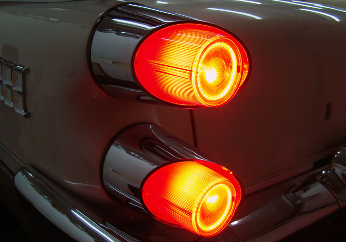 (06 Stop & Directional Light.jpg) (06 Stop & Directional Light.jpg)
Attachments
----------------
01 Circular Red LED.jpg (72KB - 533 downloads)
02 LED with Carrier and Connector.jpg (57KB - 516 downloads)
03 Circular LED in Taillight Lens.jpg (106KB - 546 downloads)
04 DSC07835 Cable Feedthrough.jpg (89KB - 534 downloads)
05 Circular Red LED ON.jpg (41KB - 531 downloads)
06 Stop & Directional Light.jpg (87KB - 553 downloads)
|
|
| |
|
Board Moderator & Exner Expert 10K+
Posts: 13062
Location: Southern Sweden - Sturkö island | As always, Serge is constantly looking and researching for to make improvements. This update will give a more aggressive look and for sure alert the cars behind. |
|
| |
|
Location: The Mile High City | Astounding! Excellent work, Serge. |
|
| |
|
Expert
Posts: 1215
Location: SWITZERLAND | LED Headlights (Supplement): By turningthe seal rubber to the top position I found out, that the strongly fixed centering collar can be removed by twisting (01). It is designed that it cannot be remounted in the wrong position (02). Thus there is no need to disassemble the cooling module and unsolder the cable for put up the rubber. Here a new reflector with convex glass as in older times, available as VALEO A082374 (03), including the seal rubber for H4/H7 bulbs (04). There is as well no need to cut out and grind the center as well, as for the one shown from the original sealed glass headlight. Together some less job for an upgrade to the assembled (05). The registration and licensing office commented: we highly appreciate the brighter LED headlight as equipped in new cars, for security reasons. They are approved with certificate by the car manufacturers. For LED headlight kits actually there are still no certificates available, as usual for rim and tire kits. - SERGE -
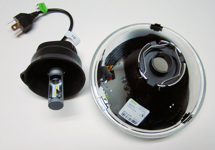 (01 Collar removed by twisting.jpg) (01 Collar removed by twisting.jpg)
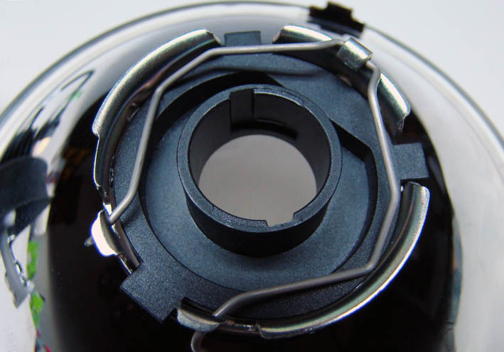 (02 Collar fixed in Reflector.jpg) (02 Collar fixed in Reflector.jpg)
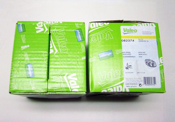 (03 Boxes VALEO 082374.jpg) (03 Boxes VALEO 082374.jpg)
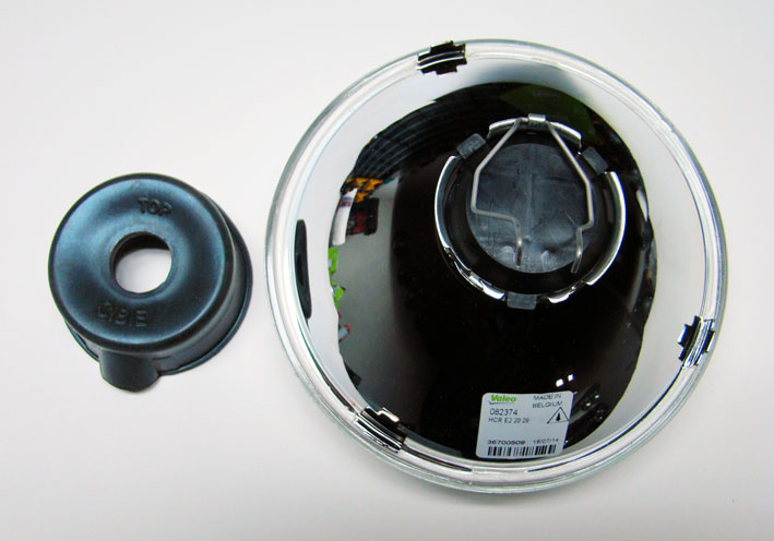 (04 Content with Seal Rubber.jpg) (04 Content with Seal Rubber.jpg)
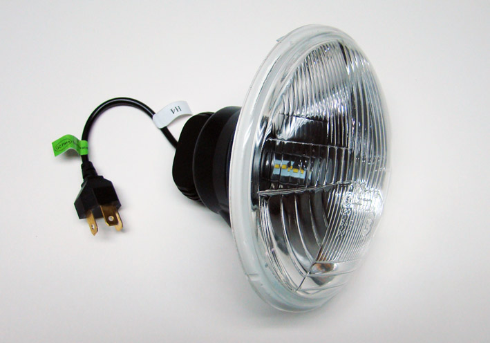 (05 LED Unit with Convex Glass.jpg) (05 LED Unit with Convex Glass.jpg)
Attachments
----------------
01 Collar removed by twisting.jpg (72KB - 730 downloads)
02 Collar fixed in Reflector.jpg (75KB - 741 downloads)
03 Boxes VALEO 082374.jpg (91KB - 734 downloads)
04 Content with Seal Rubber.jpg (78KB - 711 downloads)
05 LED Unit with Convex Glass.jpg (78KB - 693 downloads)
|
|
| |
|
Expert
Posts: 1215
Location: SWITZERLAND | 56D500boy - 2017-03-16 4:42 AM Any details on the source of those LED light rings, Serge? :) Various sizes and colors of LED rings are offered in eBay, mostly from China. Cannot post links, for they are timed-out shortly. - SERGE - |
|
| |
|
Board Moderator & Exner Expert 10K+
Posts: 13062
Location: Southern Sweden - Sturkö island | The convex glass is what I like the most and it keeps the retro look with much improved light.
It would be nice to see the convex one mounted on your car for comparison Serge. |
|
| |
|
Expert
Posts: 1215
Location: SWITZERLAND | wizard - 2017-03-16 12:52 PM The convex glass is what I like the most and it keeps the retro look with much improved light. It would be nice to see the convex one mounted on your car for comparison Serge. Headlight Glass: According the suggestion of Sven (wizard) I mounted a convex glass beside a flat glass (01). As the flat glass has a border of 14mm and angled diameter, at a first glance, it seems to be bigger (02). But the embossement of the flat glass in comparison to the original sealed glass is about identical (03). Convinced the suggestion of Sven, I switched all headlight reflectors from flat glass to convex glass (04) - and I like! Thanks to Sven. Now the inner border of the chrome bezel has become visible again, as it was original (05), and the headlights here, as can be seen, are equipped with LEDs. – SERGE - Technical information: The measured current consumption of the LED Headlight is 1.64A at 12.0 Volts, exact same value for both filaments, hi and lo, tested each single (06). Further values: 10.0Volts/1.00A, 11.0Volts/1.99A, 13Volts/1.47A, 14Volts/1.38A. At 10 Volts the intensity of the light start to reduce, under 9V unusable.
Edited by sermey 2017-03-18 12:19 PM
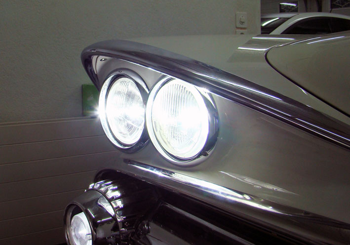 (01 Comparison Convex - Flat Glass ON.jpg) (01 Comparison Convex - Flat Glass ON.jpg)
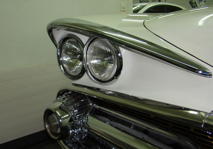 (02 Comparison Convex - Flat Glass OFF.jpg) (02 Comparison Convex - Flat Glass OFF.jpg)
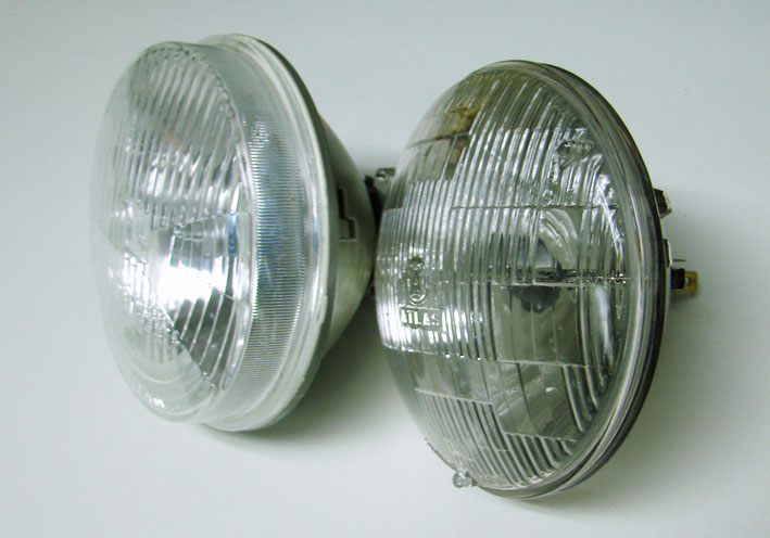 (03 Embossement of the Glasses.jpg) (03 Embossement of the Glasses.jpg)
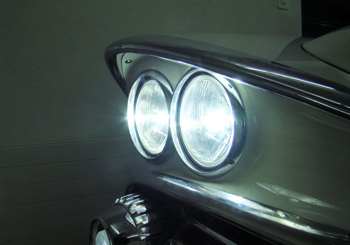 (04 Both Convex Glasses ON.jpg) (04 Both Convex Glasses ON.jpg)
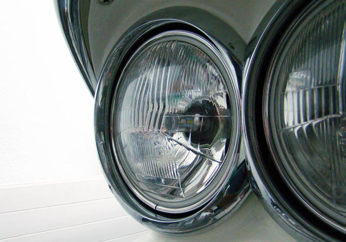 (05 Inner Border of Chrome Bezel.jpg) (05 Inner Border of Chrome Bezel.jpg)
 (06 LED Current Consumption.jpg) (06 LED Current Consumption.jpg)
Attachments
----------------
01 Comparison Convex - Flat Glass ON.jpg (84KB - 743 downloads)
02 Comparison Convex - Flat Glass OFF.jpg (92KB - 724 downloads)
03 Embossement of the Glasses.jpg (83KB - 759 downloads)
04 Both Convex Glasses ON.jpg (78KB - 718 downloads)
05 Inner Border of Chrome Bezel.jpg (86KB - 718 downloads)
06 LED Current Consumption.jpg (99KB - 745 downloads)
|
|
| |
|
Board Moderator & Exner Expert 10K+
Posts: 13062
Location: Southern Sweden - Sturkö island | That is very nice indeed Serge! The convex glasses make the car look period correct, but now with very much improved lights.
To know for the ones that dwells on this modification;
The sealed beam high beam are 50W/12 V = 4,16 Ampere x 4 "bulbs" = 16,64 Amperes total consumption
The sealed beam dipped beam are 37,5W/12V = 3,12 Ampere x 2 "bulbs" = 6,24 Amperes total consumption
This means that the power consumption will be 10 times less with those LED's on high beam !!!!
|
|
| |
|
Expert
Posts: 1530
Location: ZH, Switzerland | Hi Serge
Thanks a lot for sharing your improvements of the headlights. I think I could use H4 on my Beast, a H4/H7 system (like on your convertible) at my Letter and H7 head lights at my daily driver. Of course I would like to install fan free illumination moduls like you did. For my daily driver I assume I need a conversion module as well to prevent CAN bus errors (due to the dramatically reduced current consumption and cold wire supervision when headlight is off). Happy Restoring! Dieter |
|
| |
|
Expert
Posts: 1215
Location: SWITZERLAND | di_ch_NY56 - 2017-03-19 8:50 PM Thanks Dieter Additional explanation: A CAN BUS protection is not required for FWL-cars.Newer car models with a computer controlled unit CAN BUS, often there is an error code showing on the dash board, or the lights keep flickering and could not stay on. This is due to the fact that the LED kit is triggering a warning signal in the car's computer control unit, due to the wrong, say reduced current consumption. - SERGE -
|
|
| |
|
Board Moderator & Exner Expert 10K+
Posts: 13062
Location: Southern Sweden - Sturkö island | Check the Delta http://www.deltalights.com/
|
|
| |
|
Expert
Posts: 1215
Location: SWITZERLAND | LED Headlights (Instructions): Now I have got another set as spare parts from another supplier, this time with an instructions sheet (01). Could save some additional job getting this before! Added as well a PDF-File, ready for printing (02). - SERGE -
Edited by sermey 2017-03-24 5:25 AM
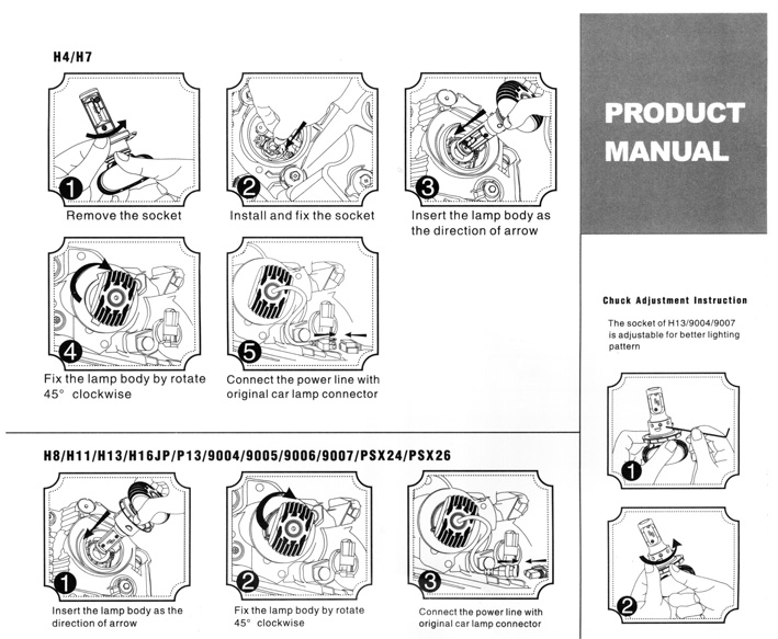 (01 LED Instructions.jpg) (01 LED Instructions.jpg)
Attachments
----------------
01 LED Instructions.jpg (149KB - 693 downloads)
02 LED Instructions 150dpi.pdf (200KB - 690 downloads)
|
|
| |
|
Expert
Posts: 1215
Location: SWITZERLAND | Rubber of Windshield Washer Foot Control: Years ago restoring my car I replaced all rubbers by new repro ones, as the one of the windshield washer control (01). Most of them dissolved, became soft and sticky as a chewing gum, and thus deformed, as well this one, never applied this washer pump (02). As for the Headlight Beamer Switch I found various sizes of similar rubbers from 3M (03). I cut and grinded one of the size 30mm to fit around the foot lever (04). Now mounted, this material will remain as it, not as original, but durable and fits optically to the neighbor switch. - SERGE -
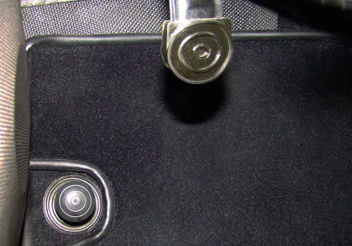 (01 Repro Rubber Mounted.jpg) (01 Repro Rubber Mounted.jpg)
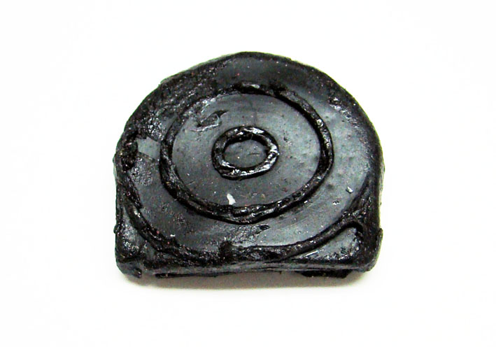 (02 Repro Rubber Dissolved.jpg) (02 Repro Rubber Dissolved.jpg)
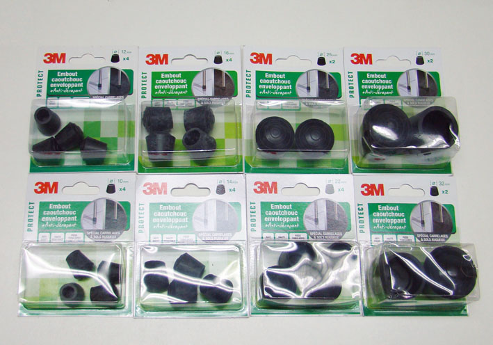 (03 3M Rubber Sizes.jpg) (03 3M Rubber Sizes.jpg)
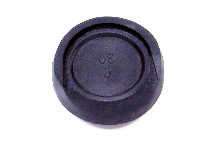 (04 New Rubber Cut as Collar.jpg) (04 New Rubber Cut as Collar.jpg)
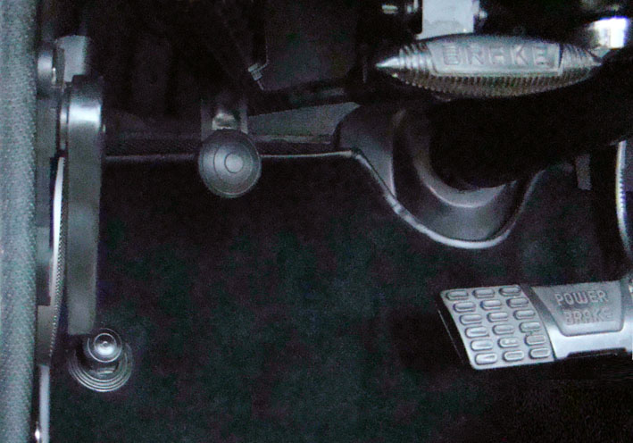 (05 New Rubber Mounted.jpg) (05 New Rubber Mounted.jpg)
Attachments
----------------
01 Repro Rubber Mounted.jpg (106KB - 699 downloads)
02 Repro Rubber Dissolved.jpg (70KB - 716 downloads)
03 3M Rubber Sizes.jpg (109KB - 683 downloads)
04 New Rubber Cut as Collar.jpg (57KB - 688 downloads)
05 New Rubber Mounted.jpg (95KB - 697 downloads)
|
|
| |
|
Expert
Posts: 1215
Location: SWITZERLAND | Unique Lancer Emblem: Recently I found a Lancer Emblem as on my glove box (01), but in bigger size, approx. 5 inches tall, never seen before (02). The first owner worked for Chrysler/Dodge in styling, back in the 1950's and 1960'. This emblem was a prototype designated for the rear fender of the 1959 Dodge to come, a previous version of the later D-500 Emblem. In fact, in comparison the knight has exact the same size as the D-500 Emblem, just other sided (03). On the back it had some clay, was hand-crafted and has 3 threaded holes for studs, not shelled as production emblems, correspondingly more heavy (04). Just the spear behind is missing, the clearance was already provided. After restoring, adding mounting screws and painting, this Unique Lancer Emblem got a new look and ready for mount (05). I found a nice place, in the center between the rear seats, by replacing the Round Knight Emblem, a spinner hubcap insert (06). To get this Knight Emblem somewhat steeped in the upholstery, I had added an electric cover behind, as shown (07). Due to the sharp edges of the Unique Lancer Emblem I cut a protecting rubber with 4mm offset to prevent damages on the upholstery (08), then fixed it with stranded steel wires (09). Final Front View (10). Now, this 1959 Dodge Custom Royal Lancer Convertible is fitted with a unique Original Lancer Emblem, another exclusive eye-catcher (11). - SERGE - :laugh:
Edited by sermey 2017-05-06 5:12 PM
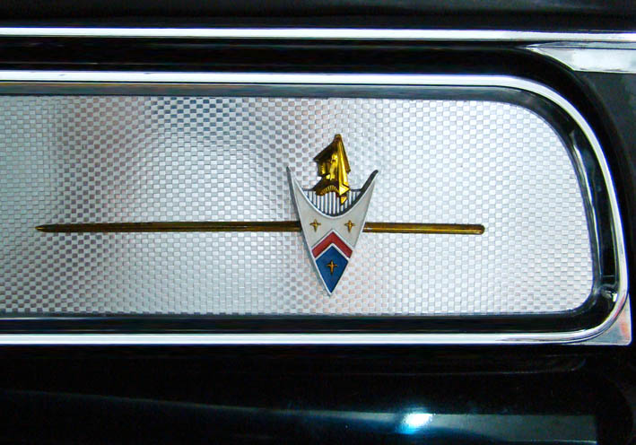 (01 Emblem Glovebox.jpg) (01 Emblem Glovebox.jpg)
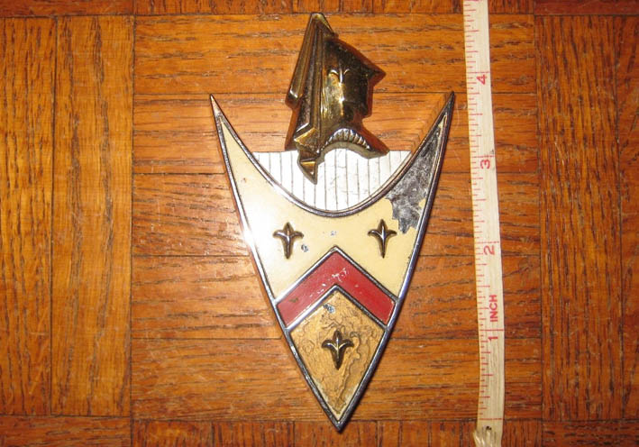 (02 Big Lancer Emblem.jpg) (02 Big Lancer Emblem.jpg)
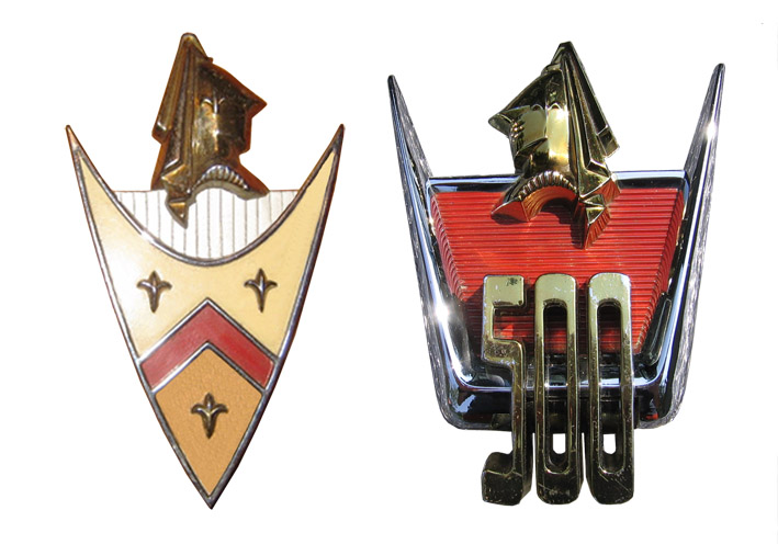 (03 Comparison Lancer to D-500 Emblem.jpg) (03 Comparison Lancer to D-500 Emblem.jpg)
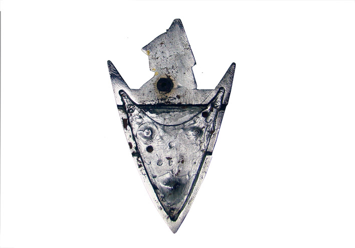 (04 Lancer Emblem Rear View.jpg) (04 Lancer Emblem Rear View.jpg)
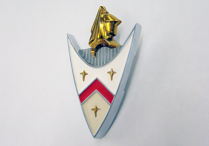 (05 Restored Unique Lancer Emblem.jpg) (05 Restored Unique Lancer Emblem.jpg)
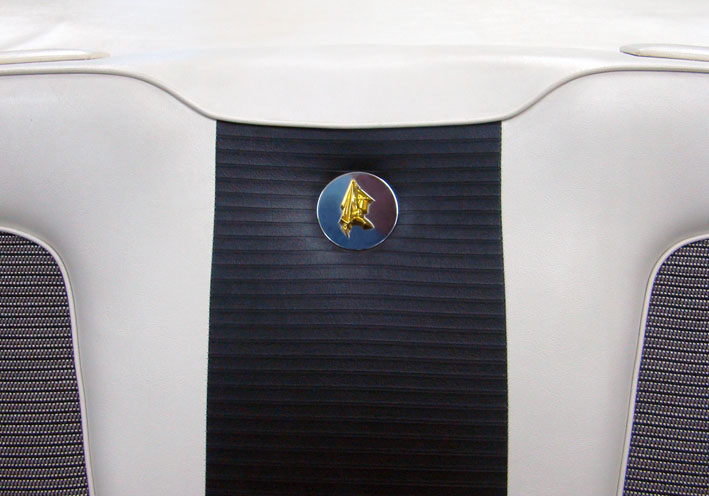 (06 Round Knight Emblem.jpg) (06 Round Knight Emblem.jpg)
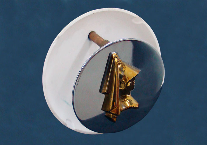 (07 Mounting Assembly.jpg) (07 Mounting Assembly.jpg)
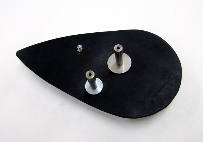 (08 Rear Protecting Rubber.jpg) (08 Rear Protecting Rubber.jpg)
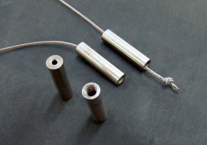 (09 Fixing with stranded Steel Wires.jpg) (09 Fixing with stranded Steel Wires.jpg)
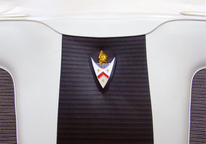 (10 Mounted Lancer Emblem.jpg) (10 Mounted Lancer Emblem.jpg)
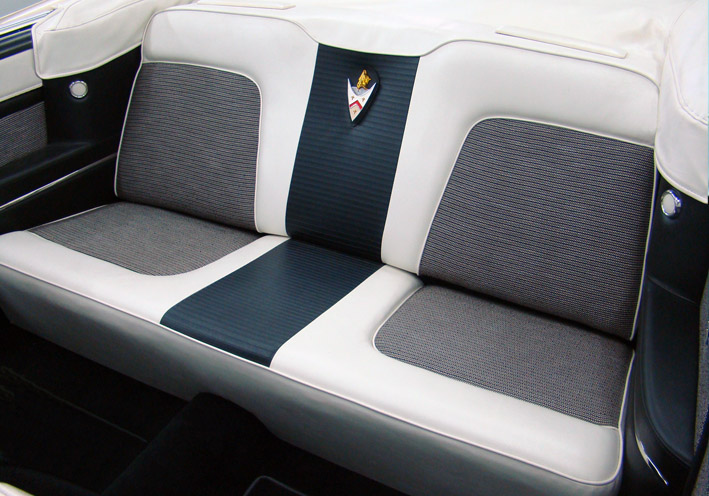 (11 Final Panoramic View.jpg) (11 Final Panoramic View.jpg)
Attachments
----------------
01 Emblem Glovebox.jpg (95KB - 717 downloads)
02 Big Lancer Emblem.jpg (105KB - 695 downloads)
03 Comparison Lancer to D-500 Emblem.jpg (100KB - 701 downloads)
04 Lancer Emblem Rear View.jpg (70KB - 685 downloads)
05 Restored Unique Lancer Emblem.jpg (63KB - 697 downloads)
06 Round Knight Emblem.jpg (82KB - 693 downloads)
07 Mounting Assembly.jpg (60KB - 701 downloads)
08 Rear Protecting Rubber.jpg (64KB - 708 downloads)
09 Fixing with stranded Steel Wires.jpg (62KB - 676 downloads)
10 Mounted Lancer Emblem.jpg (102KB - 695 downloads)
11 Final Panoramic View.jpg (118KB - 679 downloads)
|
|
| |
|
Expert
Posts: 1215
Location: SWITZERLAND | Rear Center Armrest: Looking at the rear seats, now with the Unique Lancer Emblem, I feel something is missing: a Rear Center Armrest. In the floor I found a Rear Center Armrest from a 560SEC Black, as once I had the idea to build all the sophisticated interior into the Dodge. Then I abandoned this project and sold all, except this part (01). I designed a bracket to fix it free of the two seat bodies, and removable at any time without tools (02), then bent it accordingly (03). Later the Armrest will be covered black and white with the original material as the front Center Armrest (04). The bracket is partly black coated to be invisible, can see how the back seat fits in (05). Now the rear seats looks more comfortable, not so impressive as the 300F ones, but as well full equipped and complete (06). - SERGE -
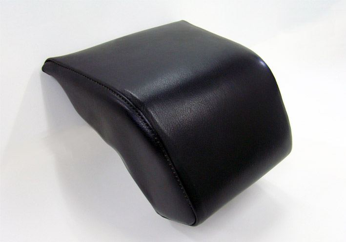 (01 Rear Center Armrest MB560 Black.jpg) (01 Rear Center Armrest MB560 Black.jpg)
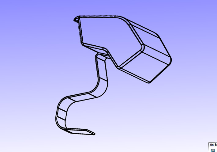 (02 CAD Design Alu Profile.jpg) (02 CAD Design Alu Profile.jpg)
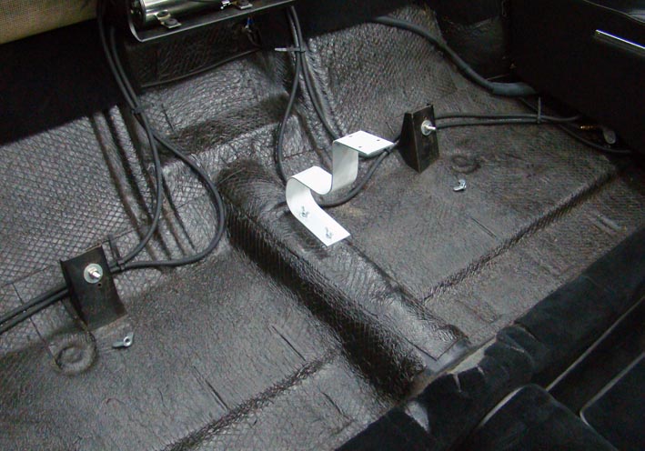 (03 Bracket Check before Black coated.jpg) (03 Bracket Check before Black coated.jpg)
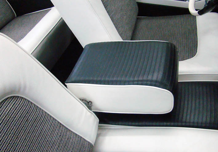 (04 Front Center Armrest.jpg) (04 Front Center Armrest.jpg)
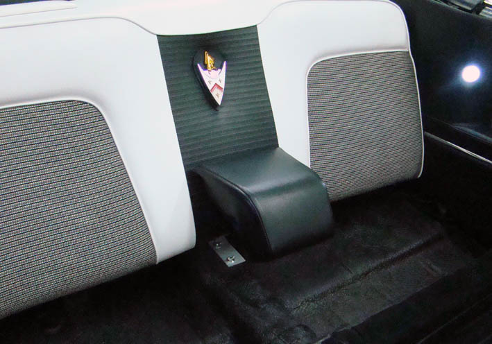 (05 Back Seat Mounted.jpg) (05 Back Seat Mounted.jpg)
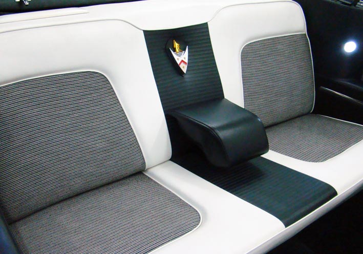 (06 Assembled Rear Seats.jpg) (06 Assembled Rear Seats.jpg)
Attachments
----------------
01 Rear Center Armrest MB560 Black.jpg (68KB - 682 downloads)
02 CAD Design Alu Profile.jpg (65KB - 716 downloads)
03 Bracket Check before Black coated.jpg (93KB - 666 downloads)
04 Front Center Armrest.jpg (88KB - 681 downloads)
05 Back Seat Mounted.jpg (88KB - 683 downloads)
06 Assembled Rear Seats.jpg (97KB - 670 downloads)
|
|
| |
|
Board Moderator & Exner Expert 10K+
Posts: 13062
Location: Southern Sweden - Sturkö island | That's our Serge, always innovative and open minded. Perhaps a cover in the same material as the seat center will add to the overall look.
I like as well that it's easy to change back to the oem if wanted. |
|
| |
|
Location: The Mile High City | I couldn't think of a better car for that unique lancer emblem to grace - especially in the way you have done it. The armrest upholds your own very high standards - well done, Serge! |
|
| |
|
Expert
Posts: 1215
Location: SWITZERLAND | Rear Center Armrest 2: I felt the complain of many of you about missing Originality. Now I corrected it according the Front Center Armrest, first virtually by CAD and PS, later will become real (01). - SERGE -
Edited by sermey 2017-05-20 11:42 AM
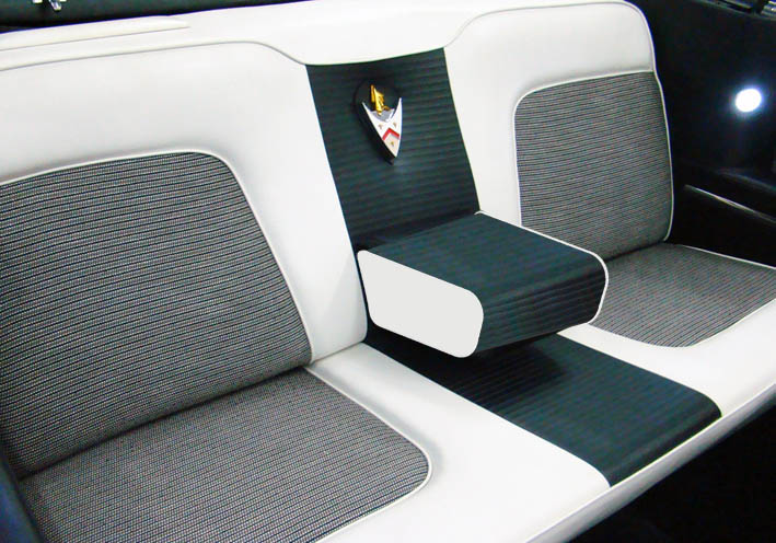 (07 Assembled Rear Seats OR.jpg) (07 Assembled Rear Seats OR.jpg)
Attachments
----------------
07 Assembled Rear Seats OR.jpg (101KB - 673 downloads)
|
|
| |
|
Exner Expert 10K+
Posts: 10042
Location: Lower Mainland BC | sermey - 2017-05-20 11:32 AM Now I corrected it according the Front Center Armrest, first virtually by CAD and PS, later will become real ( SERGE -
Very nice. I was going to suggest that the first version was nice but it didn't match the front armrest. Now you've fixed that (or will).
|
|
| |
|
Expert
Posts: 1215
Location: SWITZERLAND | Armrest Stainless Trim: The door panel armrests of the 1956 Dodge Custom Royal are fitted with a surrounding stainless trim (01) (02), pictures courtesy of Dave (56D500boy). As I like this “Make-up” I was looking for original, used stainless trims (03). I found as well new, but shorter ones, not surrounding the armrest (04). For my 1959 DODGE Custom Royal I preferred these trims, feeling they look more decent. The two pieces design of the armrest enable dual colors (05). Shape the new trim to fit the curve and simply fix it (06). This stainless trim can easy be removed. In direct comparison the effect is apparent (07). A visible de-luxe aspect (08) (09), and an additional touch of extravagance for an extraordinary car (10). – SERGE – :)
Edited by sermey 2017-12-18 7:24 AM
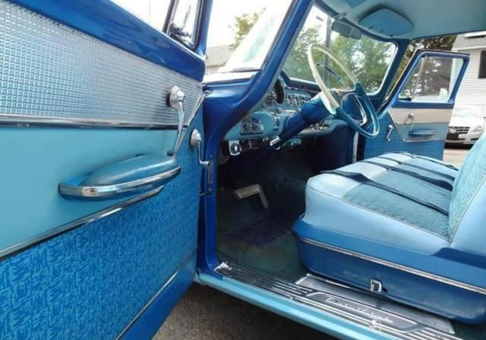 (01 1956 Dodge Custom Royal Armrest.jpg) (01 1956 Dodge Custom Royal Armrest.jpg)
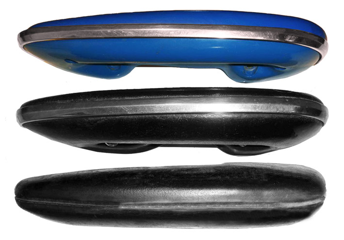 (02 Added Stainless Trim.jpg) (02 Added Stainless Trim.jpg)
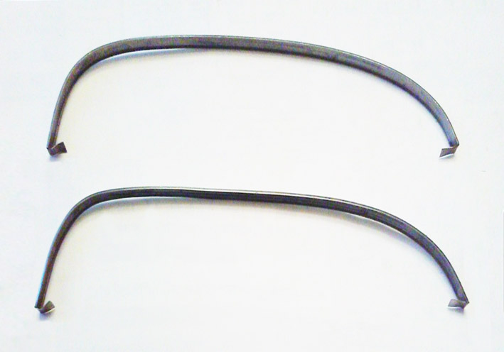 (03 Used Stainless Trim.jpg) (03 Used Stainless Trim.jpg)
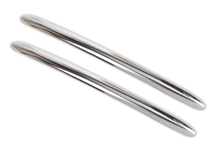 (04 New Stainless Trim Short.jpg) (04 New Stainless Trim Short.jpg)
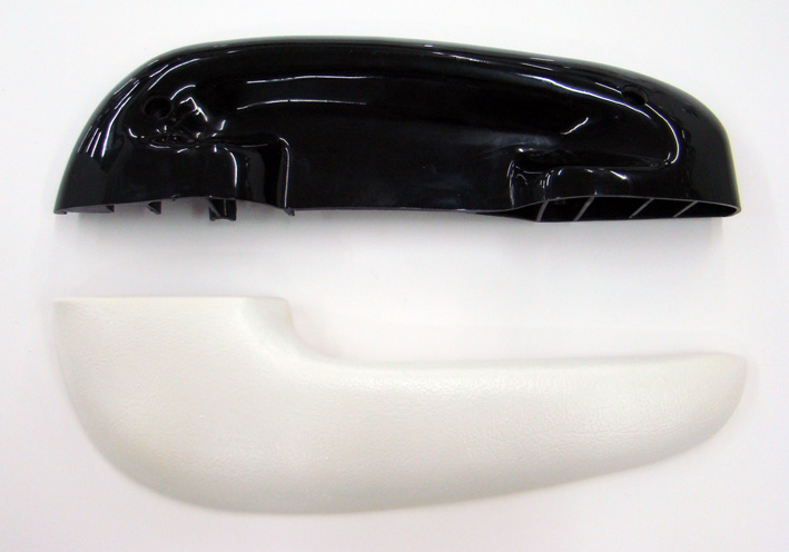 (05 Armrest Disassembled.jpg) (05 Armrest Disassembled.jpg)
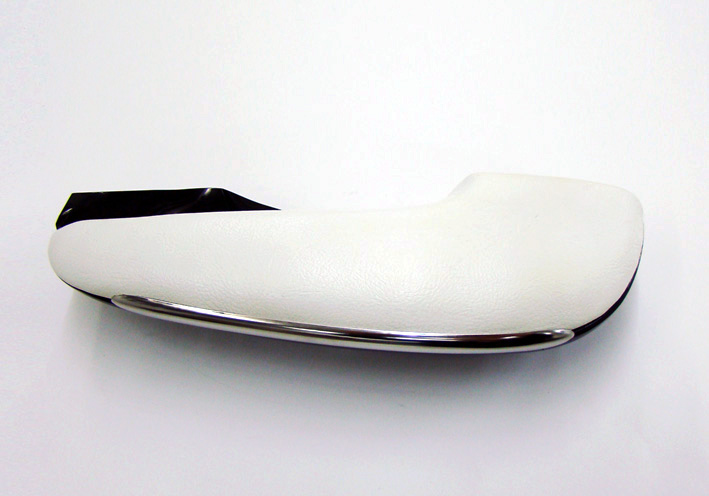 (06 New Stainless Trim Fixed.jpg) (06 New Stainless Trim Fixed.jpg)
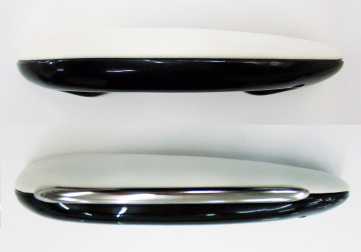 (07 Comparison.jpg) (07 Comparison.jpg)
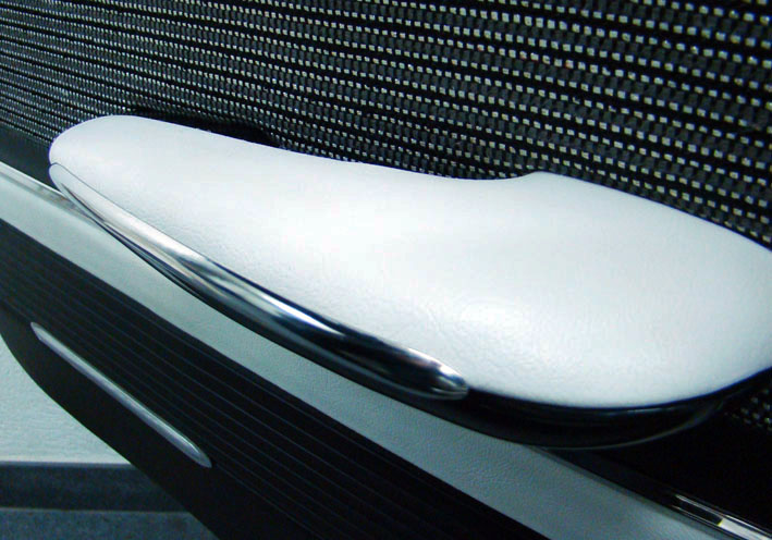 (08 Assembly Mounted.jpg) (08 Assembly Mounted.jpg)
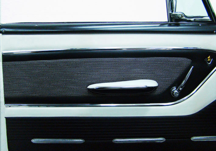 (09 Assembly Front View.jpg) (09 Assembly Front View.jpg)
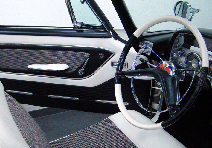 (10 Door Panel Final View.jpg) (10 Door Panel Final View.jpg)
Attachments
----------------
01 1956 Dodge Custom Royal Armrest.jpg (101KB - 632 downloads)
02 Added Stainless Trim.jpg (87KB - 656 downloads)
03 Used Stainless Trim.jpg (53KB - 624 downloads)
04 New Stainless Trim Short.jpg (74KB - 635 downloads)
05 Armrest Disassembled.jpg (91KB - 635 downloads)
06 New Stainless Trim Fixed.jpg (80KB - 609 downloads)
07 Comparison.jpg (69KB - 608 downloads)
08 Assembly Mounted.jpg (110KB - 606 downloads)
09 Assembly Front View.jpg (108KB - 618 downloads)
10 Door Panel Final View.jpg (162KB - 605 downloads)
|
|
| |
|
Expert 5K+
Posts: 5037
| I like the armrest treatment a lot. |
|
| |
|
Expert
Posts: 1215
Location: SWITZERLAND | Your latest version looks white(r). Depend on light: artificial light in room, neon day-light in garage, flash light, setting brightness, foto filter . . . and always same camera! Then: armrest cleaned . . . a whiter shade of pale?
Edited by sermey 2017-12-18 10:46 PM
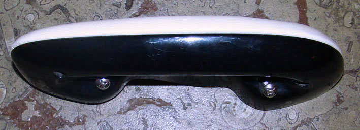 (DSC01945Lcorr.jpg) (DSC01945Lcorr.jpg)
Attachments
----------------
DSC01945Lcorr.jpg (63KB - 610 downloads)
|
|
| |
|
Expert
Posts: 1215
Location: SWITZERLAND | Single Oval Exhaust Tips: As always shown in an earlier article in this thread, I presented my Dual Oval Exhaust Tips: http://www.forwardlook.net/forums/forums/thread-view.asp?tid=23691&start=138 Here is shown how the same stainless Exhaust Tip can easy be mounted in the single version, animated with CAD (2012/13). It needs two holes and two screws, preferably M6 (01). The exhaust tip is fixed on the lower part of the tube at direct accessibility (02), is best when positioned till the end of the tip (03). Then paint black inside the outlet. If the space requires it can as well be mounted on the other side, or adjusted with distances. No cutting is needed. Now the heat cannot affect the visible upper part of the Exhaust Tip, protected by the gap. it will always remain nice and shiny (04). Many FWL.owner may like this simple solution. – SERGE – :) N.B. Additional an eDrawing-file is added (2013) Today I found another supplier, but exact the same device and at lowered price: Endrohre Edelstahl AMG Style 350x85x58 oval http://www.ebay.de/itm/JOM-Mercedes-Look-Sport-Auspuff-Endrohr-schrag-oval-85x58-mm-Edelstahl-gerade/
Edited by sermey 2018-01-14 6:36 AM
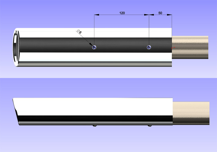 (01 Oval Exhaust Tip Dimensions.jpg) (01 Oval Exhaust Tip Dimensions.jpg)
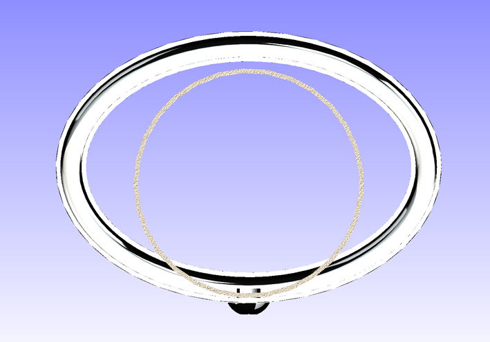 (02 Oval Exhaust Tip RearView.jpg) (02 Oval Exhaust Tip RearView.jpg)
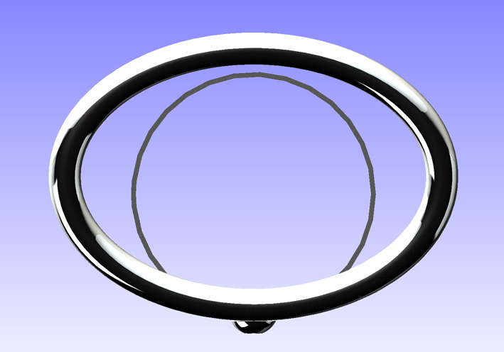 (03 Oval Exhaust Tip FrontView.jpg) (03 Oval Exhaust Tip FrontView.jpg)
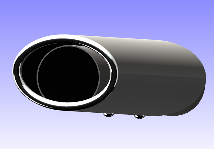 (04 Oval Exhaust Tip Outlet.jpg) (04 Oval Exhaust Tip Outlet.jpg)
Attachments
----------------
01 Oval Exhaust Tip Dimensions.jpg (68KB - 601 downloads)
02 Oval Exhaust Tip RearView.jpg (86KB - 587 downloads)
03 Oval Exhaust Tip FrontView.jpg (80KB - 602 downloads)
04 Oval Exhaust Tip Outlet.jpg (61KB - 582 downloads)
2018 SW13 2012-10-11 Oval Exhaust Tip.eprt (182KB - 610 downloads)
|
|
| |
|
Expert
Posts: 1215
Location: SWITZERLAND | Jumbo Oval Exhaust Tip: As time goes, one’s view may change, progressing to other, new trends. First I started with two slanted stainless tubes pushed over the exhaust pipe. Then came the dual round tips, and latest the dual oval exhaust tips, both presented in this thread. The oval AMG style looks very sporty, but in dual somewhat too modern for an oldtimer. Now I found what would better fit on my 1959 DODGE (except the original Exhaust Deflectors): Because it is big I call it Jumbo Oval Exhaust Tip, in stainless steel, measured size 150x80x265mm, double layer, feather edge 16mm (01). It looks compact, solid, traditional and is optically best suitable to big cars (02). The fixing is provided by welding, offering diameters 60 – 50mm selected by cutting. The small diameter is exact the same as the exhaust tube (51mm) to be mounted. (03). As I want all options for an easy positioning, turning, adjusting or removing I had to modify. The inlet diameter was manually cut around the upper part of the connection, then spreading (04). Upper, for the exhaust will move rather downwards the bumper. Adding a stainless bracket, the unit becomes ready for push over the uncut tube (05) and to be fixed (06). Here adjusted in final position (07). While the Dual Oval Exhaust Tips demonstrated speed and power, the new type represents rather a discrete grandness as in older times (08). - SERGE - :)
 (01 Jumbo Exhaust Tip Front View.jpg) (01 Jumbo Exhaust Tip Front View.jpg)
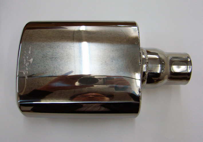 (02 Jumbo Exhaust Tip Top View.jpg) (02 Jumbo Exhaust Tip Top View.jpg)
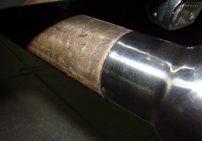 (03 Tubes same Diameter 51mm.jpg) (03 Tubes same Diameter 51mm.jpg)
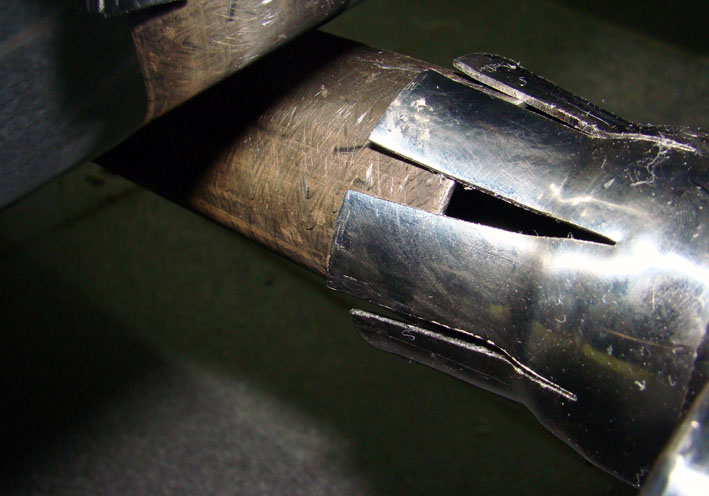 (04 Connection Cut and Spread.jpg) (04 Connection Cut and Spread.jpg)
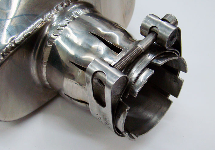 (05 Ready for Mount.jpg) (05 Ready for Mount.jpg)
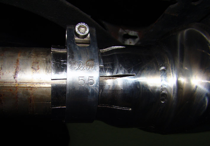 (06 Exhaust Tip Fixed.jpg) (06 Exhaust Tip Fixed.jpg)
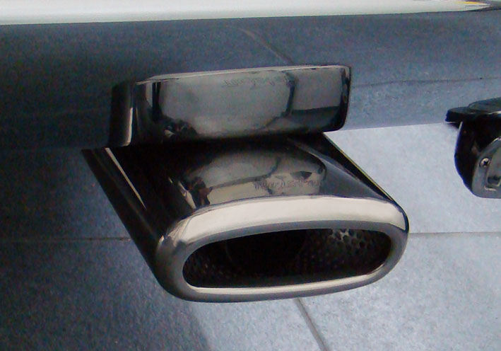 (07 Exhaust Tip Mounted.jpg) (07 Exhaust Tip Mounted.jpg)
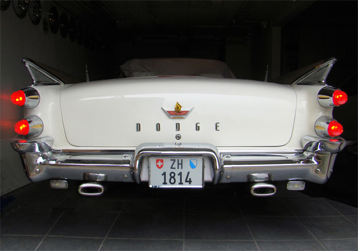 (08 Jumbo Exhaust Tips Overall Rear View ZH.jpg) (08 Jumbo Exhaust Tips Overall Rear View ZH.jpg)
Attachments
----------------
01 Jumbo Exhaust Tip Front View.jpg (70KB - 607 downloads)
02 Jumbo Exhaust Tip Top View.jpg (84KB - 601 downloads)
03 Tubes same Diameter 51mm.jpg (68KB - 599 downloads)
04 Connection Cut and Spread.jpg (82KB - 591 downloads)
05 Ready for Mount.jpg (85KB - 589 downloads)
06 Exhaust Tip Fixed.jpg (82KB - 588 downloads)
07 Exhaust Tip Mounted.jpg (79KB - 600 downloads)
08 Jumbo Exhaust Tips Overall Rear View ZH.jpg (119KB - 578 downloads)
|
|
| |
|
Expert
Posts: 1215
Location: SWITZERLAND | On special request: here the link of the supplier for the JUMBO Oval Exhaust Tips: https://www.quality-tuning.eu/us/universal-stainless-steel-exhaust-tip-oval-155x75-l265-in60-50-double-layer Note: no need to cut the exhaust tube. - SERGE - :) |
|
| |
|
Expert
Posts: 1215
Location: SWITZERLAND | sermey - 2017-05-20 5:32 PM . . . first virtually by CAD and PS, now becoming real . . . Rear Center Armrest 3: The final armrest has been optimized according the front armrest, and built using the original material for the upholstery (01) The mounting bracket has got dual for higher stability, a hinge to swivel up the armrest when needed, and then also coated with the original center material (02). To better absorb the lateral forces and for an easier alignment, an additional T-bracket was used, fixed on the left and right side. (03). Now the armrest can be mounted, the position aligned to center (04). To avoid rattle and keep the armrest steady in any position, the hinge got some strong Loctite (05). Finally the rear seats appear as an integral unit, as could be original – another unique feature (06). - SERGE - ;)
N.B. The seat and the seatback can be removed with mounted Armrest! Edited by sermey 2018-01-29 8:14 AM
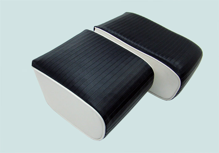 (01 Center Armrests Front - Rear.jpg) (01 Center Armrests Front - Rear.jpg)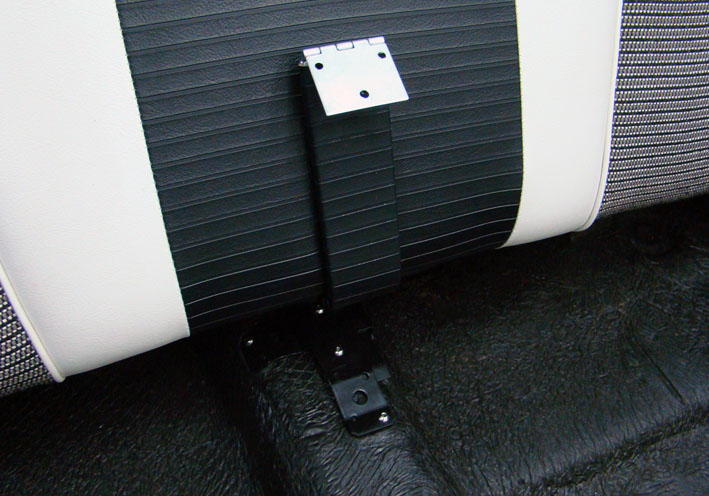 (02 Coated Dualbracket with Hinge.jpg) (02 Coated Dualbracket with Hinge.jpg)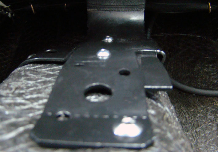 (03 Additional T-Bracket.jpg) (03 Additional T-Bracket.jpg)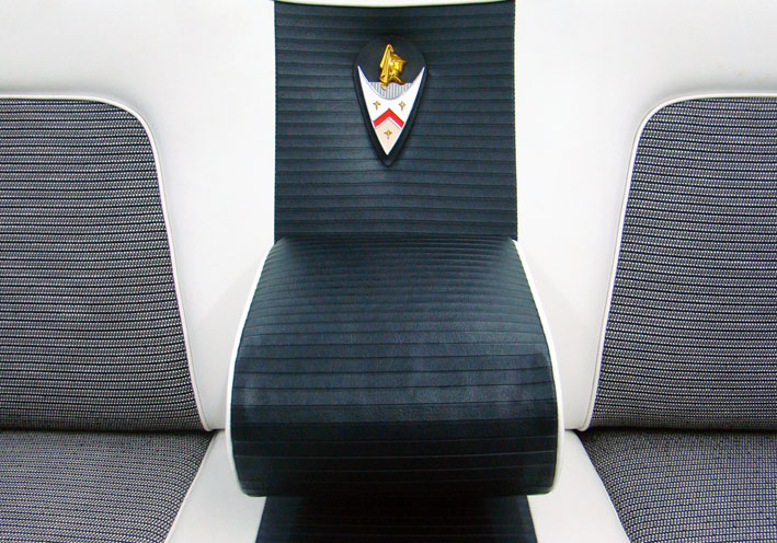 (04 Alignment Check.jpg) (04 Alignment Check.jpg)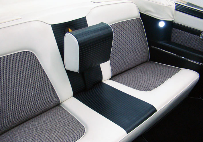 (05 Rear Center Armrest up.jpg) (05 Rear Center Armrest up.jpg)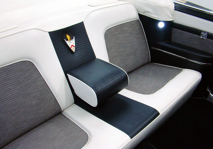 (06 Rear Center Armrest Final View.jpg) (06 Rear Center Armrest Final View.jpg)Attachments ---------------- 01 Center Armrests Front - Rear.jpg (66KB - 604 downloads) 02 Coated Dualbracket with Hinge.jpg (101KB - 606 downloads) 03 Additional T-Bracket.jpg (75KB - 588 downloads) 04 Alignment Check.jpg (142KB - 642 downloads) 05 Rear Center Armrest up.jpg (115KB - 593 downloads) 06 Rear Center Armrest Final View.jpg (106KB - 598 downloads) |
|
| |
|
Expert
Posts: 1215
Location: SWITZERLAND | Front Center Armrest: I remember when I got my Dodge many years ago: around the pivot axes the upholstery was broken due to friction with the angled bracket. This should never happen with the newly upholstered armrest. Here I present how I did. I used two screws (M8) as axis fitted with a nylon bearing, and two nylon shims each side as distance (01) to preserve a minimum gap between bracket and armrest (02), avoiding any mechanical friction (03). To spread the strong bracket up to 2mm needs a heavy wrench tool (04). Since then till today, the armrest moves smoothly up and down as on ball bearing, without risk of any damage (05). – SERGE -
Edited by sermey 2018-01-31 12:33 PM
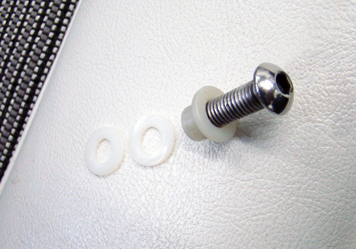 (01 Fixing Items.jpg) (01 Fixing Items.jpg)
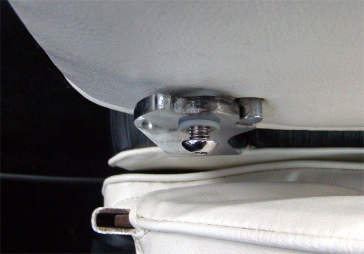 (02 Assembling.jpg) (02 Assembling.jpg)
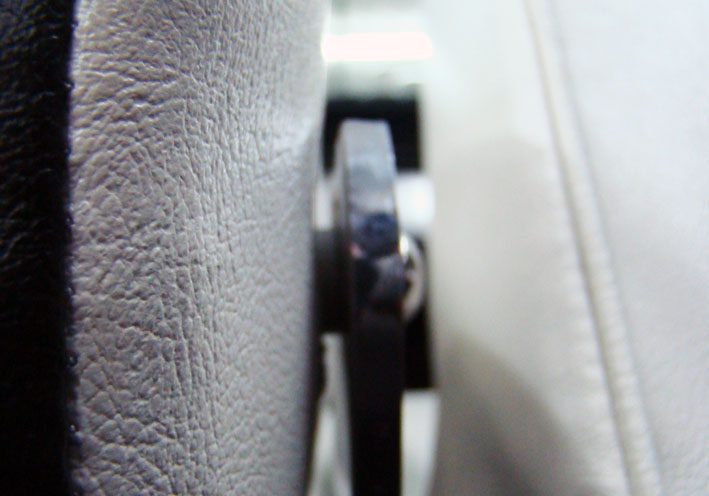 (03 Gap to Armrest.jpg) (03 Gap to Armrest.jpg)
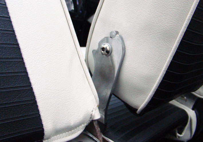 (04 Mounted Pivot.jpg) (04 Mounted Pivot.jpg)
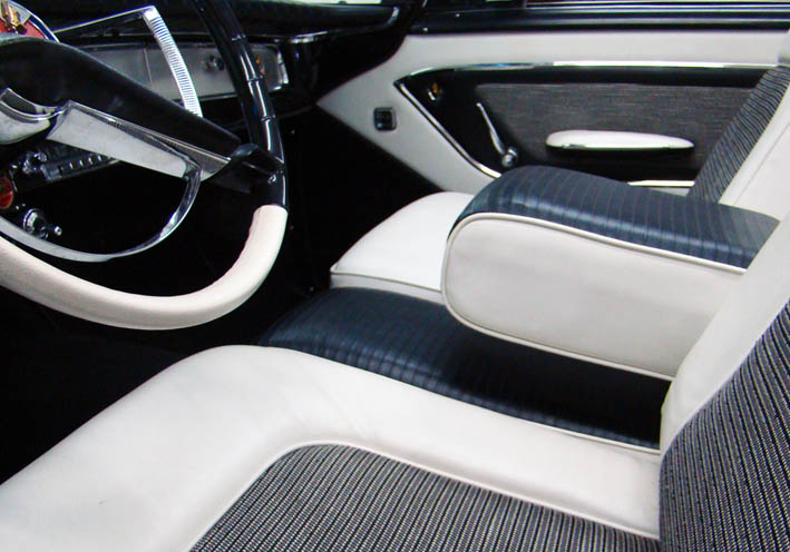 (05 Front Center Armrest Positioned.jpg) (05 Front Center Armrest Positioned.jpg)
Attachments
----------------
01 Fixing Items.jpg (96KB - 676 downloads)
02 Assembling.jpg (77KB - 607 downloads)
03 Gap to Armrest.jpg (72KB - 593 downloads)
04 Mounted Pivot.jpg (87KB - 584 downloads)
05 Front Center Armrest Positioned.jpg (85KB - 607 downloads)
|
|
| |
|
Expert
Posts: 1215
Location: SWITZERLAND | Horn Ring Pad 2: The padless horn ring is found mostly in non Custom Royal Dodges. As they look heavy “chromy” I was thinking, how it could be optically upgraded. I designed in 3D-CAD two identical custom made pads without the center part (02), assembled them pinky colored to the horn ring picture (03). A flattened dual template was generated (04), as well a separate printable 1 : 1 PDF-File is added (14). Print-out and stick on an aluminium panel of 0.5mm, cut around with a metal-scissor (05), then manually pre-bend on an edge, aligned to the white center line. The reference length is 117.5mm. Fine grind and bend the two metal channels manually to fit on the horn ring (06), to be ready for coating (07). Any material can be used for coating. I used the same vinyl as for the door panels, matching to the interior (08). The vinyl contour can be cut “in the air” with a standard scissor (09). Instead of using the Alu-Pads, carpet tape is applied to the vinyl pad for direct fixing (10). Starting to join to the horn ring on the outer side (11). Now the naked horn ring has got a bikini. With some additional paint in the center (red and golden), the make-up of the horn ring may be accentuated (12). A reversible upgrade for non CR-Owners, as it would be original,. For comparison here presented just on one side (13). – SERGE -
Edited by sermey 2018-02-11 11:28 AM
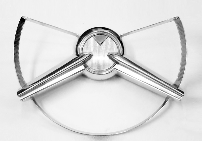 (01 Horn Ring Padless.jpg) (01 Horn Ring Padless.jpg)
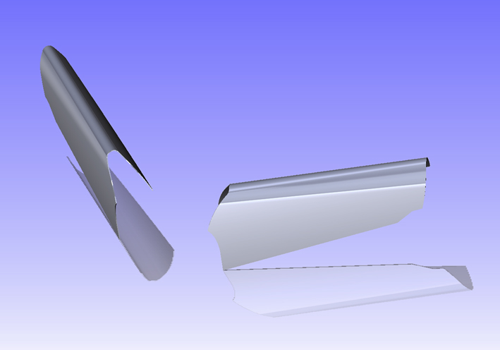 (02 Dual Horn Pad 3D-CAD.jpg) (02 Dual Horn Pad 3D-CAD.jpg)
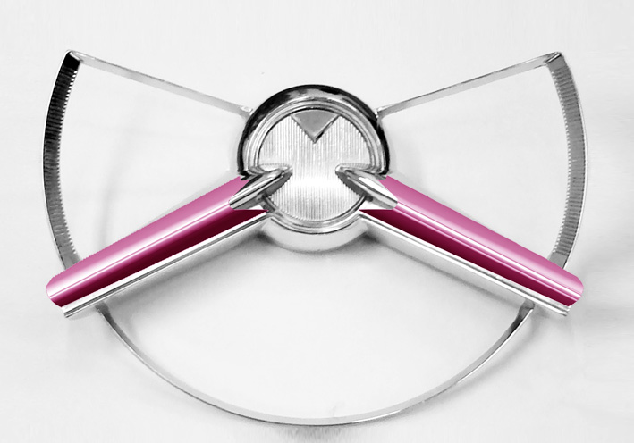 (03 Horn Pads CAD in Pinky Virtual Mounted.jpg) (03 Horn Pads CAD in Pinky Virtual Mounted.jpg)
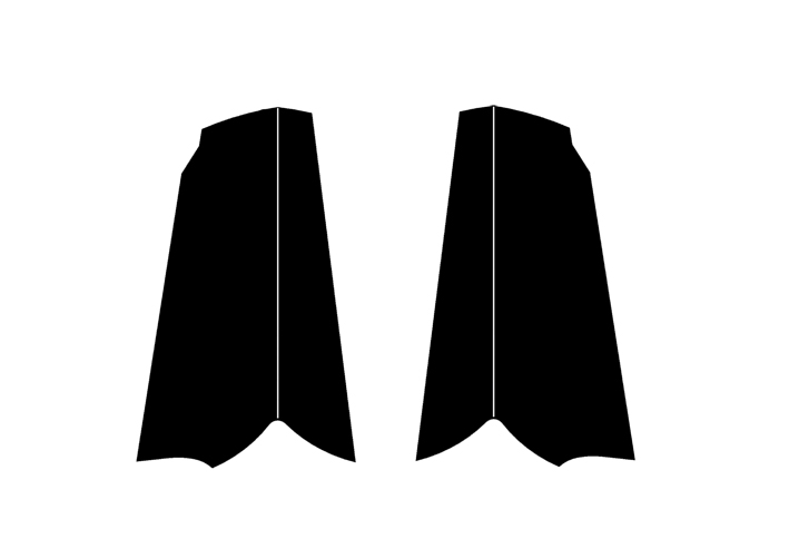 (04 Dual Template for cut Horn Pad.jpg) (04 Dual Template for cut Horn Pad.jpg)
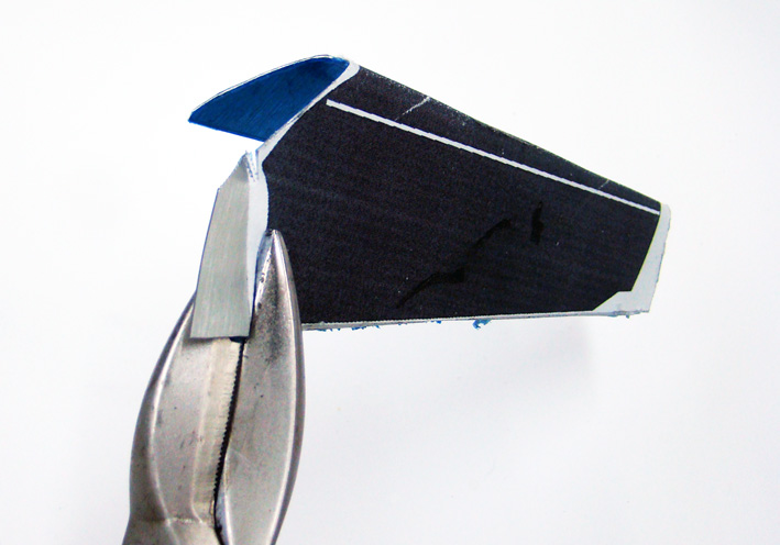 (05 Cutting Alu-Pad.jpg) (05 Cutting Alu-Pad.jpg)
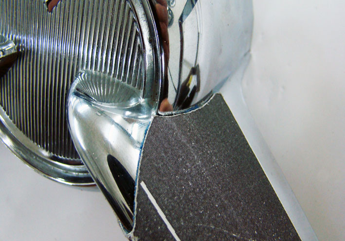 (06 First Check.jpg) (06 First Check.jpg)
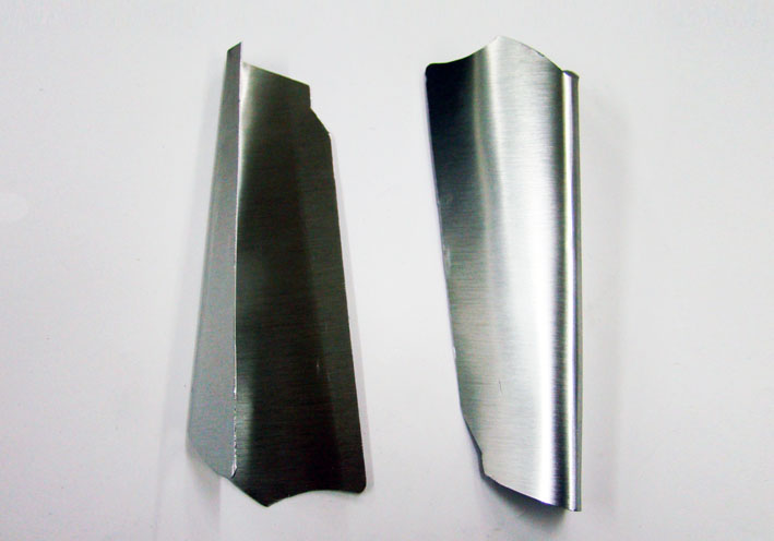 (07 Cut and Bent Alu-Pads Ready for Coating.jpg) (07 Cut and Bent Alu-Pads Ready for Coating.jpg)
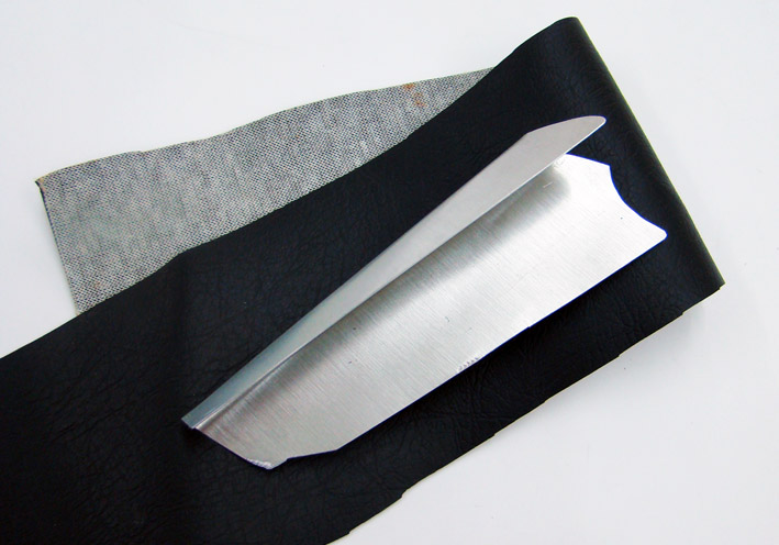 (08 Black Vinyl for Coating.jpg) (08 Black Vinyl for Coating.jpg)
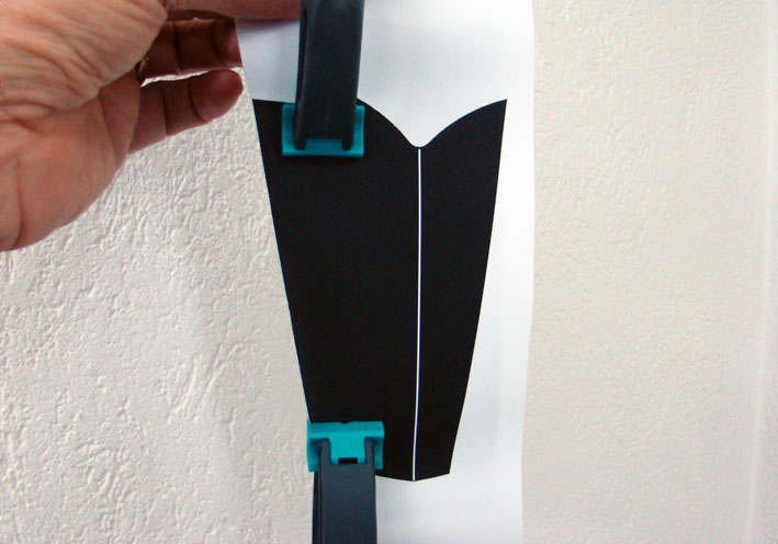 (09 Cut the Vinyl Contour in the Air.jpg) (09 Cut the Vinyl Contour in the Air.jpg)
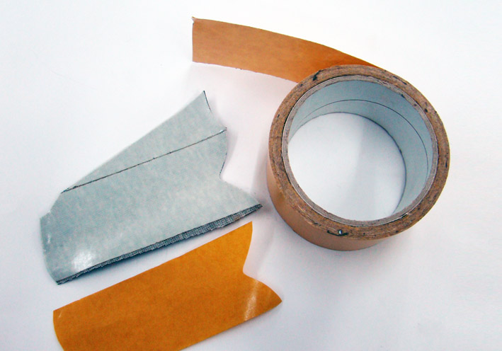 (10 Applying Carpet Tape.jpg) (10 Applying Carpet Tape.jpg)
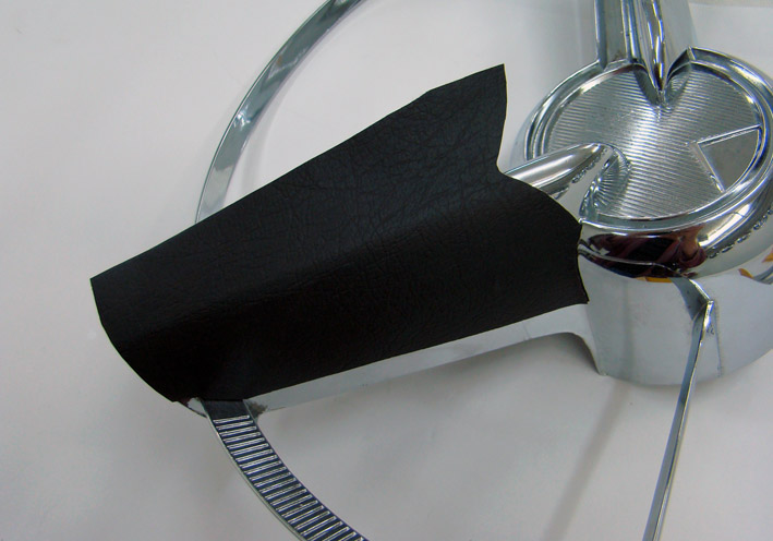 (11 Join to the Horn Ring.jpg) (11 Join to the Horn Ring.jpg)
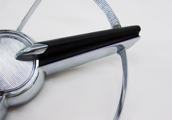 (12 One Side Lateral View.jpg) (12 One Side Lateral View.jpg)
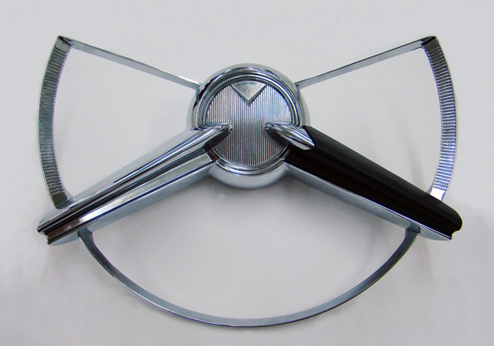 (13 One Side Top View.jpg) (13 One Side Top View.jpg)
Attachments
----------------
01 Horn Ring Padless.jpg (86KB - 607 downloads)
02 Dual Horn Pad 3D-CAD.jpg (110KB - 577 downloads)
03 Horn Pads CAD in Pinky Virtual Mounted.jpg (91KB - 591 downloads)
04 Dual Template for cut Horn Pad.jpg (59KB - 674 downloads)
05 Cutting Alu-Pad.jpg (93KB - 583 downloads)
06 First Check.jpg (111KB - 576 downloads)
07 Cut and Bent Alu-Pads Ready for Coating.jpg (52KB - 580 downloads)
08 Black Vinyl for Coating.jpg (92KB - 577 downloads)
09 Cut the Vinyl Contour in the Air.jpg (73KB - 569 downloads)
10 Applying Carpet Tape.jpg (83KB - 609 downloads)
11 Join to the Horn Ring.jpg (87KB - 600 downloads)
12 One Side Lateral View.jpg (81KB - 584 downloads)
13 One Side Top View.jpg (83KB - 584 downloads)
14 Dual Template Horn Pad L117.5 A4 300dpi.pdf (178KB - 582 downloads)
|
|
| |
|
Expert
Posts: 1215
Location: SWITZERLAND | On Street: In WideView, from Original 1000mm/600dpi reduced to 500mm/72dpi, for it fits here. - SERGE -
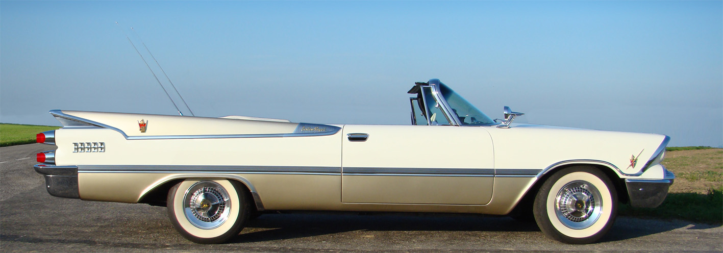 (01 1959 DODGE Custom Royal Convertible 500-72dpi.jpg) (01 1959 DODGE Custom Royal Convertible 500-72dpi.jpg)
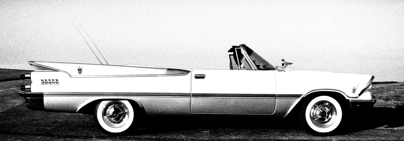 (02 1959 DODGE Custom Royal Convertible styled 500-72dpi.jpg) (02 1959 DODGE Custom Royal Convertible styled 500-72dpi.jpg)
Attachments
----------------
01 1959 DODGE Custom Royal Convertible 500-72dpi.jpg (174KB - 579 downloads)
02 1959 DODGE Custom Royal Convertible styled 500-72dpi.jpg (196KB - 574 downloads)
|
|
| |
|
Expert
Posts: 1215
Location: SWITZERLAND | Push Button Labels 1: In an earlier thread Ishowed how to restore damaged buttons by grinding the front part down to a flat surface, as needed 1 – 2 mm, all the buttons same amount and put on stickers. http://www.forwardlook.net/forums/forums/thread-view.asp?tid=23691&start=206 Unfortunately the applied letters look different as original, for the same font could not be found. In the first part I present here in 3D-RealView how this fault can easy be corrected. Most is self-explaining by pictures. The second part will show the practical implementation including a printable template. Original push buttons assembly (01), original buttons (02), grinded front (R40) to become flat (03), modeled letters R N D 1 2 with the appropriate color (04), applied on transparency (05), labels print and cut out (06). Exploded assembly with the labels (07), put the labels on the buttons without any glue (08) or in front of the metal cap, and the new push buttons assembly looks as original, ready to mount (09). No tools, no dirty hands - just a fine coffee along the way. – SERGE - :)
Edited by sermey 2018-03-04 7:10 AM
 (01 Original Push Buttons Assembly.jpg) (01 Original Push Buttons Assembly.jpg)
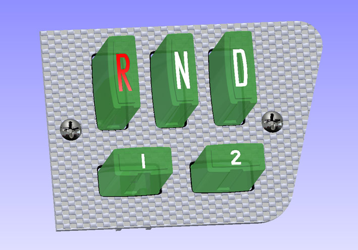 (02 Original Push Buttons.jpg) (02 Original Push Buttons.jpg)
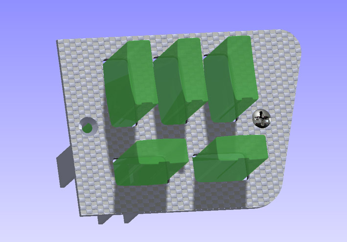 (03 Grinded Push Buttons.jpg) (03 Grinded Push Buttons.jpg)
 (04 All Letters Modeled.jpg) (04 All Letters Modeled.jpg)
 (05 Letters Applied on Transpareny.jpg) (05 Letters Applied on Transpareny.jpg)
 (06 All Labels Cut Out Solo.jpg) (06 All Labels Cut Out Solo.jpg)
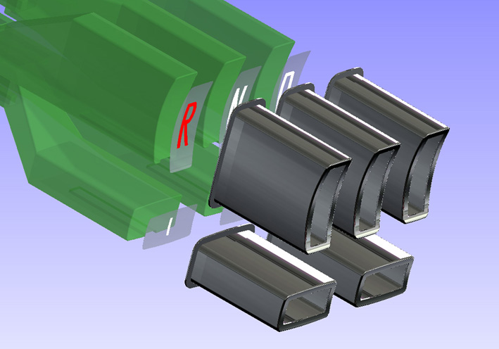 (07 Push Buttons with Label Exploded View.jpg) (07 Push Buttons with Label Exploded View.jpg)
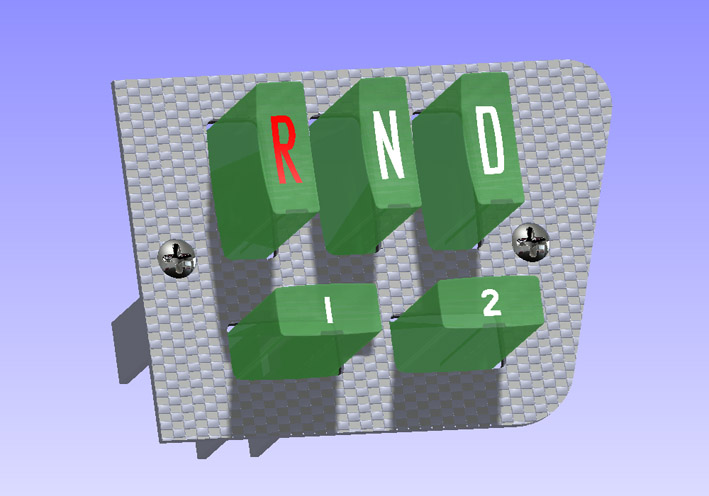 (08 Labeled Push Buttons.jpg) (08 Labeled Push Buttons.jpg)
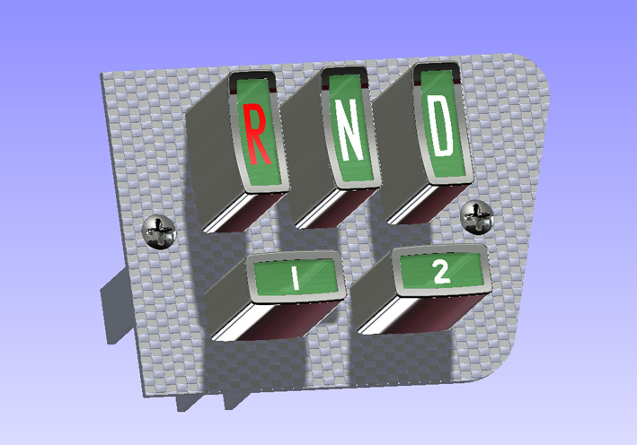 (09 Labeled Push Buttons Assembly .jpg) (09 Labeled Push Buttons Assembly .jpg)
Attachments
----------------
01 Original Push Buttons Assembly.jpg (116KB - 575 downloads)
02 Original Push Buttons.jpg (108KB - 591 downloads)
03 Grinded Push Buttons.jpg (79KB - 587 downloads)
04 All Letters Modeled.jpg (38KB - 576 downloads)
05 Letters Applied on Transpareny.jpg (60KB - 588 downloads)
06 All Labels Cut Out Solo.jpg (43KB - 594 downloads)
07 Push Buttons with Label Exploded View.jpg (93KB - 586 downloads)
08 Labeled Push Buttons.jpg (84KB - 573 downloads)
09 Labeled Push Buttons Assembly .jpg (115KB - 578 downloads)
|
|
| |
|
Expert
Posts: 1215
Location: SWITZERLAND | Armrest Stainless Trim 2: When I had coated the upper part of my black armrests to interior white vinyl, I found later a pair of earlier armrests in black, same shape but all in one piece, as spare parts to turn back to original if one day demanded (01). I grinded in water (P600) to remove signs of (lady) nails, and threated them to get the surface as new (02). Meanwhile the purchased Mopar Stainless Trims (early Imperial) arrived and got polished (03). To mount straight and gapless was tricky, as the length was very tight: First bent both ends to fit in the armrest, grind the armrest 6 x 0.3 mm to fix the center position (04). When clipped in on both sides imposed to the body to get well centered (05). In comparison I found these Mopar trims better performing to my car (06) and replaced the recent shorter ones (07). Now the armrests appear Mopar like, not just a nice add-on as before, but with an original option (08). - SERGE - :)
N.B. On the earlier one-piece armrest these trims may have been used to hide the separation border on the partially coated, dual color versions.
Edited by sermey 2018-03-04 10:26 AM
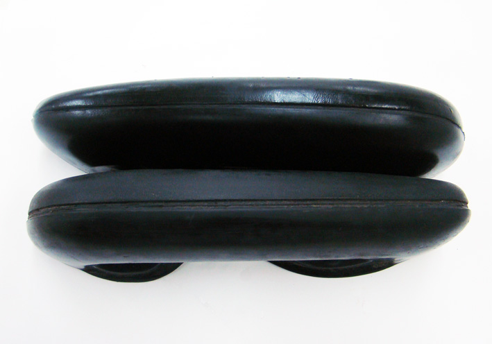 (01 Pair of one-piece Black Armrest.jpg) (01 Pair of one-piece Black Armrest.jpg)
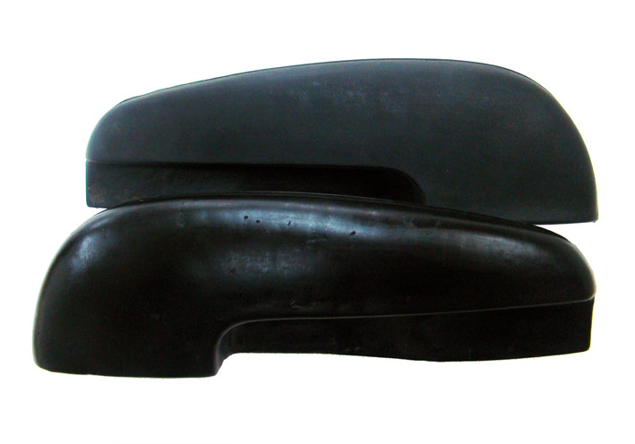 (02 Difference grinded in Water.jpg) (02 Difference grinded in Water.jpg)
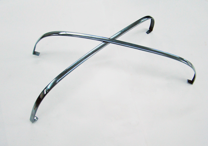 (03 Polished Trims.jpg) (03 Polished Trims.jpg)
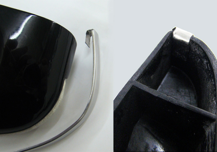 (04 Ends Pre-Bent to fit.jpg) (04 Ends Pre-Bent to fit.jpg)
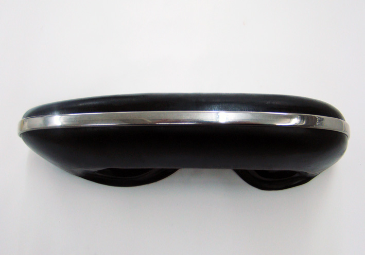 (05 Trim Centered.jpg) (05 Trim Centered.jpg)
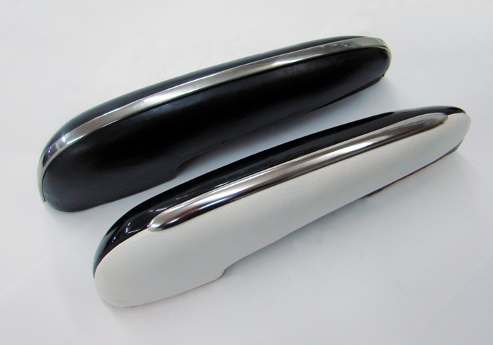 (06 Comparison Black-White Armrest.jpg) (06 Comparison Black-White Armrest.jpg)
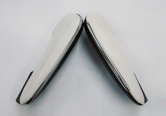 (07 Comparison on White Armrests.jpg) (07 Comparison on White Armrests.jpg)
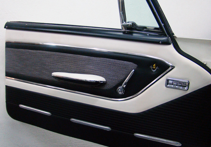 (08 Trim Assembled Final View.jpg) (08 Trim Assembled Final View.jpg)
Attachments
----------------
01 Pair of one-piece Black Armrest.jpg (81KB - 575 downloads)
02 Difference grinded in Water.jpg (70KB - 585 downloads)
03 Polished Trims.jpg (76KB - 580 downloads)
04 Ends Pre-Bent to fit.jpg (99KB - 566 downloads)
05 Trim Centered.jpg (72KB - 606 downloads)
06 Comparison Black-White Armrest.jpg (93KB - 570 downloads)
07 Comparison on White Armrests.jpg (68KB - 602 downloads)
08 Trim Assembled Final View.jpg (161KB - 569 downloads)
|
|
| |
|
Board Moderator & Exner Expert 10K+
Posts: 13062
Location: Southern Sweden - Sturkö island | Very nice Serge, your the master of detailing!!!! |
|
| |
|
Expert
Posts: 1215
Location: SWITZERLAND | STRETCHED 1959 DODGE Custom Royal Convertible: Not for thinking, just for look at! - SERGE - . . . . . . . . . . . . . . . . . . . . . . . . . . Total length: Original 553cm, Strechted 658cm
According the suggestion of Sven (Wizard) the rear door handle have been replaced and moved.
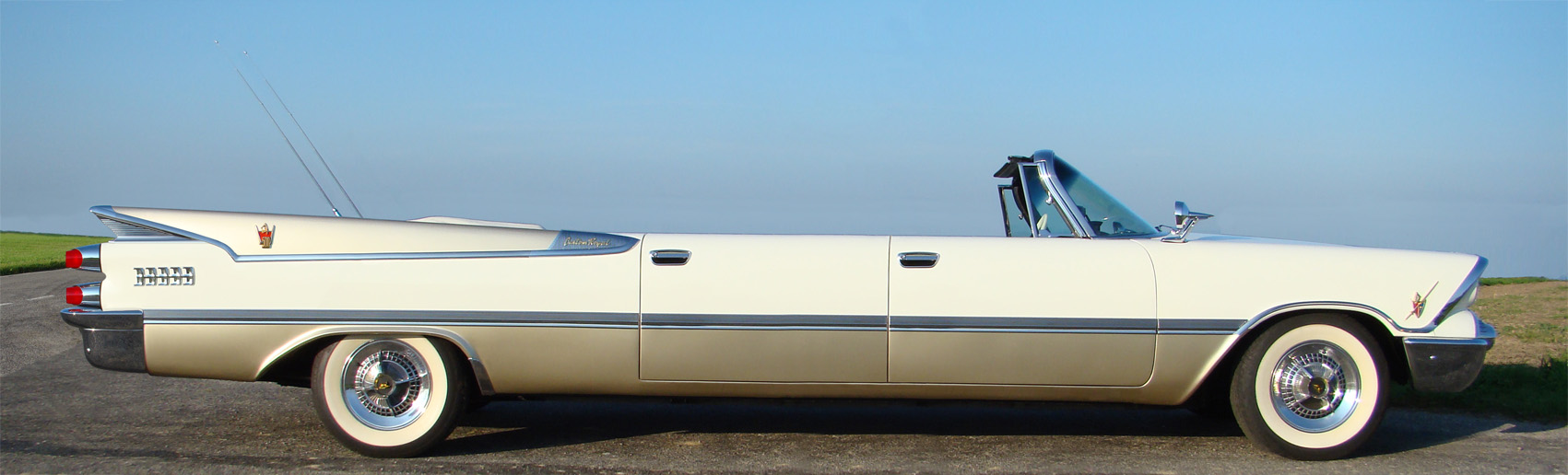 (01 STRETCHED 1959 DODGE Custom Royal Convertible 600-72dpi.jpg) (01 STRETCHED 1959 DODGE Custom Royal Convertible 600-72dpi.jpg)
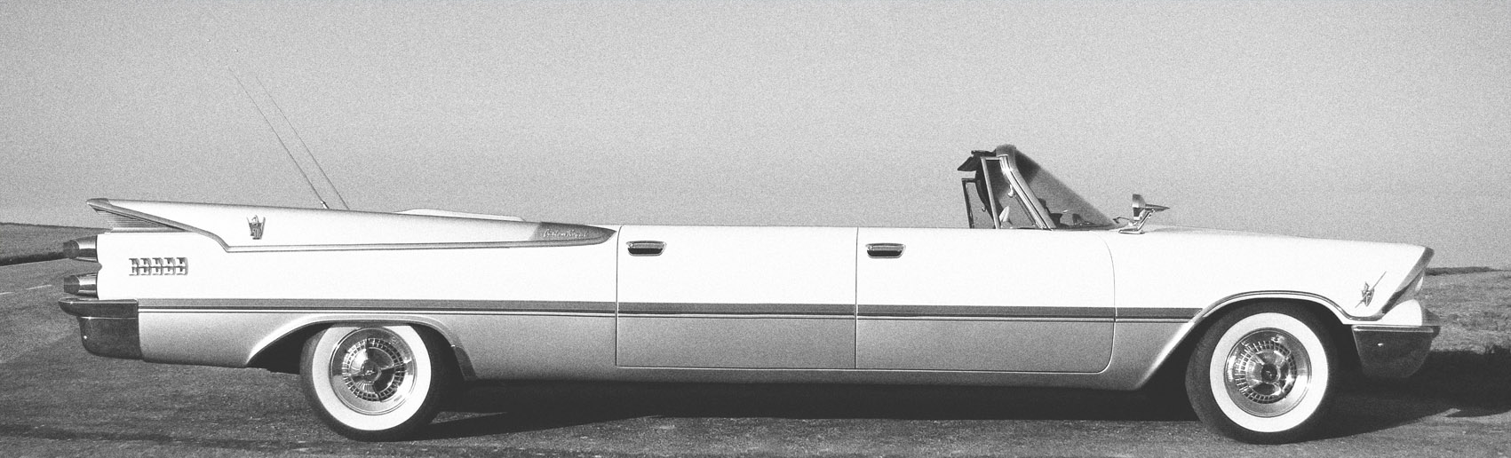 (02 STRETCHED 1959 DODGE Custom Royal Convertible styled 600-72dpi.jpg) (02 STRETCHED 1959 DODGE Custom Royal Convertible styled 600-72dpi.jpg)
 (03 STRETCHED 1959 DODGE Custom Royal Convertible RH Handle 600-72dpi.jpg) (03 STRETCHED 1959 DODGE Custom Royal Convertible RH Handle 600-72dpi.jpg)
Attachments
----------------
01 STRETCHED 1959 DODGE Custom Royal Convertible 600-72dpi.jpg (203KB - 587 downloads)
02 STRETCHED 1959 DODGE Custom Royal Convertible styled 600-72dpi.jpg (230KB - 567 downloads)
03 STRETCHED 1959 DODGE Custom Royal Convertible RH Handle 600-72dpi.jpg (204KB - 589 downloads)
|
|
| |
|
Expert
Posts: 1215
Location: SWITZERLAND | SHORTENED 1959 DODGE Custom Royal Convertible: Why not the other way down: a Roadster? - SERGE - :cool: Total length: Original 553cm, Shortened 488cm
Edited by sermey 2018-03-17 3:16 AM
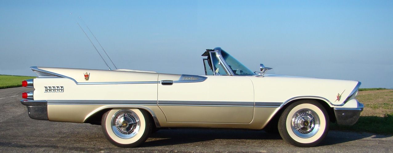 (SHORTENED 1959 DODGE Custom Royal Convertible 450-72dpi.jpg) (SHORTENED 1959 DODGE Custom Royal Convertible 450-72dpi.jpg)
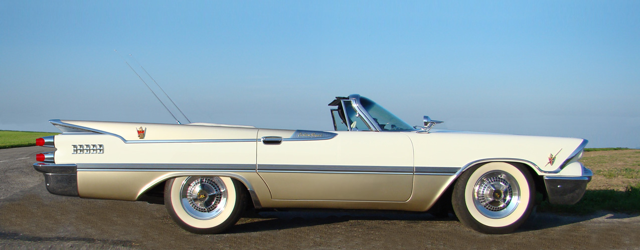 (SHORTENED FLAT 1959 DODGE Custom Royal Convertible 450-72dpi.jpg) (SHORTENED FLAT 1959 DODGE Custom Royal Convertible 450-72dpi.jpg)
Attachments
----------------
SHORTENED 1959 DODGE Custom Royal Convertible 450-72dpi.jpg (202KB - 570 downloads)
SHORTENED FLAT 1959 DODGE Custom Royal Convertible 450-72dpi.jpg (189KB - 589 downloads)
|
|
| |
|
Veteran
Posts: 241
Location: Southern CA | sermey - 2009-02-01 4:44 AM
15” Wheels and Tires: I always found, 14” Wheels on my Car are relatively too small and look poor in Proportion to the Body and its Wheelhouse. Must say, this was the Style at this time. The other Point, bigger and wider Tires have much better Adhesion on the Street, the 235/70/15 Radial Tires about +25% in Comparison to the Original 14” Diagonal ones. This improvement is necessarily needed for a full Advantage of Disk Brakes. Thus, I decided in favor of 15” Wheels and the corresponding WWW Tires, still keeping the Original 14” Wheel Set including the Spinner Hubcaps. In order to keep the Original Appearance, the Original HubCaps should fit to the 15” Rims. I bought 15” decorative stainless Rings, cut out the Border around, and soldered it inside the Wheel Cover. For a stronger Fixing on the rechromed Wheels I increased the Clamp Pression by putting a soft round PVC Profile under the Clamps. Now, the Hubcaps fit perfectly to the 15” Rims, their Edges are even protected from Curbstones due to the inner Position, and the Air Valve is perfectly centered as well. According my personal feeling, this Wheel Size gives the Car its settled Proportions. Another improvement of the Outfit, for the Drivers Security, and as an additional Benefit the Wheel Cover Edge Protection. (can see, my HubCaps are not perfect, but polished and with the sticked Black they look as)
Hey Serge, I have 15” wheels on my car also and I’m making a set of 15” hubcaps with my original 14” caps using the same method you used. Did you use a propane torch for the soldering or a different method? What type of solder and flux did you use? I’m also concerned about overheating the thin stainless and warping it. Thanks. |
|
| |
|
Expert
Posts: 1215
Location: SWITZERLAND | "What type of solder and flux did you use?" Sorrys Steve, I used the wrong expression: Not solder, but electro-weld. My friend did this on various point spots around, caring to keep the ring always centered. Fine tune by bending the fixing edges. Good luck - SERGE - |
|
| |
|
Expert
Posts: 1215
Location: SWITZERLAND | 1959 DODGE Paint Chip Set Ditzler: (as this seems to be forgotten, here again) This sheet shows the original color references on the various paint probes, individually stuck on a page. Today the exact definition of colors is described by the additive RGB (Red-Green-Blue) or the complementary subtractive CMYK (Cyan-Magenta-Yellow-Key Black) codes, mostly used in the graphics industry and generated most programs with color options by entering the corresponding codes. Using homogenous white light, a scanner delivers very accurate and reproductive results on a file. These can be used to verify or compare the color of a new paint with the original color. Just scan the new probe and compare the resulting color codes. The Original Paint Chip Set for 1959 DODGE has been scanned at high definition and cleaned without affecting the colors. For homogenous results, the color codes then have been picked (50x50px) and the values insert in the attached Paint Chip, here at limited size (144dpi, 250k) in JPG (01) and PDF (02). - SERGE -
Edited by sermey 2020-04-13 9:03 PM
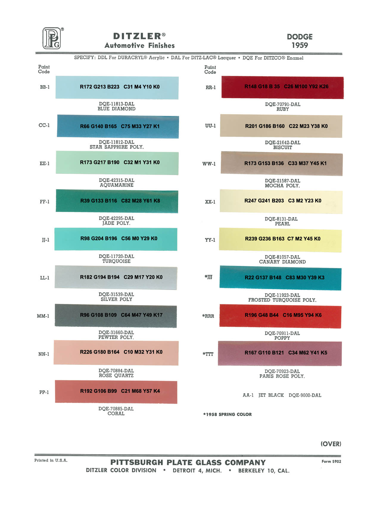 (1959 DODGE Color Ditzler 144dpi.jpg) (1959 DODGE Color Ditzler 144dpi.jpg)
Attachments
----------------
1959 DODGE Color Ditzler 144dpi.jpg (214KB - 515 downloads)
1959 DODGE Color Ditzler 130dpi.pdf (237KB - 563 downloads)
|
|
| |
|
Board Moderator & Exner Expert 10K+
Posts: 13062
Location: Southern Sweden - Sturkö island | As Always, our Serge goes Deep into the issue at hand and delivers very accurate results.
This would work best on solid paints, but metallic is more difficult;
I have several paint chip charts for ’60 Chrysler, both in paper form and digital ones – if you take my color, Bluegrass Poly (Metallic), none of the paint chip charts resemble even the slightest to the actual original color.
The only “dead ringer” I have is a hopelessly warped original paint sample in my ’60 dealers album. All the colors is fantastic clear, but unfortunately, all warped and stuck together after years of storage under wrong conditions.
I had the original and the new body paint scanned and managed to get a 98% match after some extra manual blending and I have the formula for this paint now. As you all know, 98% isn’t 100%, so one can see the difference.
For to try to match the duller magnesium metallic used at that time (nowadays aluminum (too shiny)), there’s actually no metal flakes at all, but instead pearl which gives a softer tone.
I have an acquaintance in Västerås that works as a special paint technician, he informs me that there’s a method to get next to exact match, but it’s very costly (around 10000 SEK) and they need a piece of metal with the original paint. Then they use a spectrometer for to detect every color, tone, shade and hue and for the classic cars they use a special clear coat with flattening agent (less shiny).
With this method, they painted a ’60 Pontiac blue metallic after a front end crash, to a resemblance that the owner couldn’t tell which paint was the old or the new.
There’s supposed to be a company in Holland that can blend colors with modern components after the original receipt, rumor tells me cost about 5000 SEK.
|
|
| |
|

Expert
Posts: 1223
Location: Ramona, CA | sermey - 2018-03-16 3:18 PM
SHORTENED 1959 DODGE Custom Royal Convertible: Why not the other way down: a Roadster? - SERGE - :cool: Total length: Original 553cm, Shortened 488cm
The problem with these shorties that people actually build is that they don't move the rear wheels back to maintain proper proportions. They look tail heavy. Sorry for my lacking photo modifying skills but you can see what I mean.
 (59dodgeshorty1.jpg) (59dodgeshorty1.jpg)
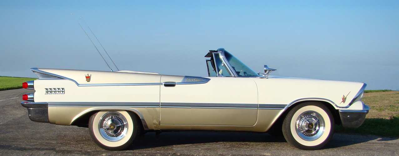 (59dodgeshorty.jpg) (59dodgeshorty.jpg)
Attachments
----------------
59dodgeshorty1.jpg (202KB - 501 downloads)
59dodgeshorty.jpg (178KB - 480 downloads)
|
|
| |
|
Expert
Posts: 1215
Location: SWITZERLAND | NicksGarage - 2020-04-14 6:04 PM sermey - 2018-03-16 3:18 PM SHORTENED 1959 DODGE Custom Royal Convertible: Why not the other way down: a Roadster? - SERGE - :cool: Total length: Original 553cm, Shortened 488cm The problem with these shorties that people actually build is that they don't move the rear wheels back to maintain proper proportions. They look tail heavy. Sorry for my lacking photo modifying skills but you can see what I mean. You are right, Nick! Not correct proportion. Now I corrected it with the flat version based on your sample, the car length still remaining the same (488cm). Thanks for your creative input. - SERGE - BTW: Now this file with the many layers has a size of 3.9Giga!
Edited by sermey 2020-04-14 4:14 PM
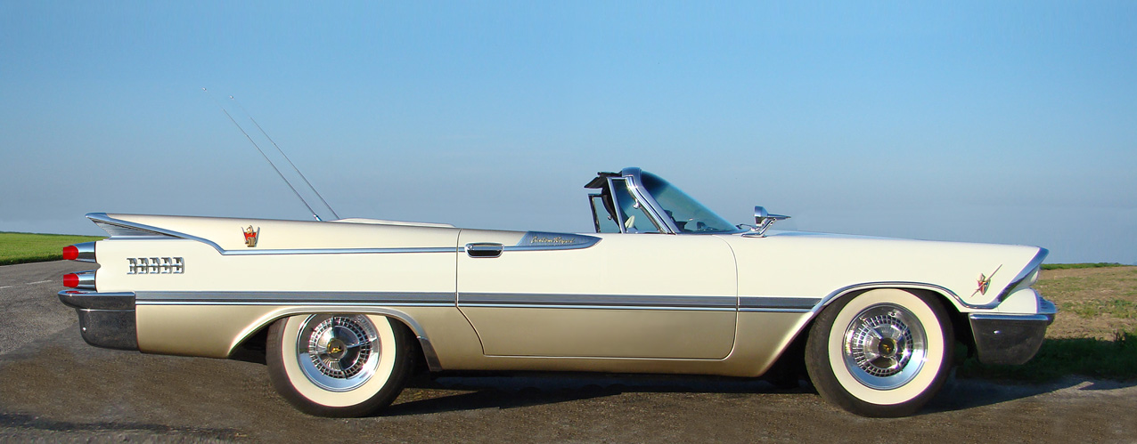 (SHORTENFlat 1959 DODGE Custom Royal Convertible 450-72 moved rear axle.jpg) (SHORTENFlat 1959 DODGE Custom Royal Convertible 450-72 moved rear axle.jpg)
Attachments
----------------
SHORTENFlat 1959 DODGE Custom Royal Convertible 450-72 moved rear axle.jpg (193KB - 460 downloads)
|
|
| |
|
Expert
Posts: 1215
Location: SWITZERLAND | 1959 DODGE CUSTOM ROYAL ORIGINAL GOLDEN KNIGHT EMBLEM – KING SIZE: Now it is realized, here presented for the first time, and available in limited quantities, electric plated in glossy gold and some in glossy chrome. 3D-designed to fit on the 1959 DODGE front grille, thus very simple and fast to mount - without any tools. It can be added and removed at anytime, anywhere and without leaving any marks. This typical emblem, an absolute eye-catcher, a visible upgrade, a jewel on your 1959 DODGE! (01) (02) (03). A product featuring SWISS Engineering and International Technology. Some details of the high technical standard are shown in (04) (05) (06). The emblem will be shipped in a safe and secure box (07) (08). Send me a PM for actual availability and price. The Mounting Instructions A5 are added. All parts of the set are listed (09), and the proceeding is illustrated (10). What a nice job! It looks as it was always there. When done: Your Golden Knight Emblem - now is ready to enjoy! -SERGE -
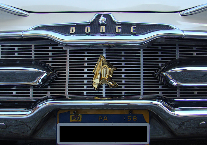 (01 Gold on Original Front.jpg) (01 Gold on Original Front.jpg)
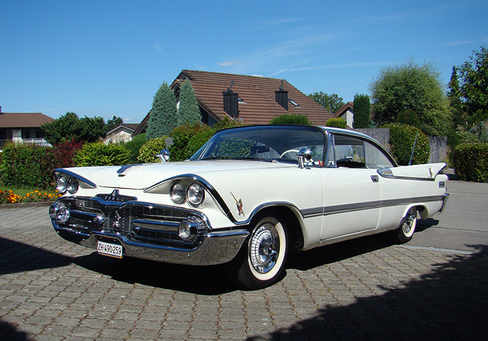 (02 Chrome on Original Front.jpg) (02 Chrome on Original Front.jpg)
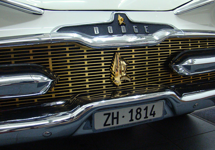 (03 Gold on SM Front.jpg) (03 Gold on SM Front.jpg)
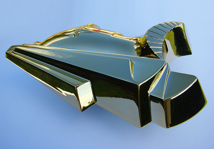 (04 Check Glossy Surface.jpg) (04 Check Glossy Surface.jpg)
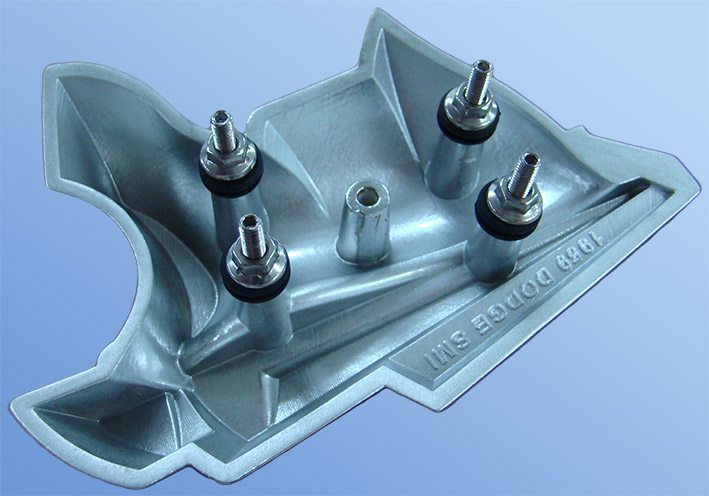 (05 Silver Rear View Solo.jpg) (05 Silver Rear View Solo.jpg)
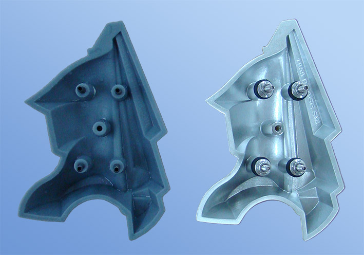 (06 Dual Rear 3D-Print - Chrome.jpg) (06 Dual Rear 3D-Print - Chrome.jpg)
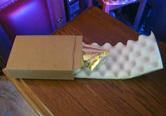 (07 Shipment Box.JPG) (07 Shipment Box.JPG)
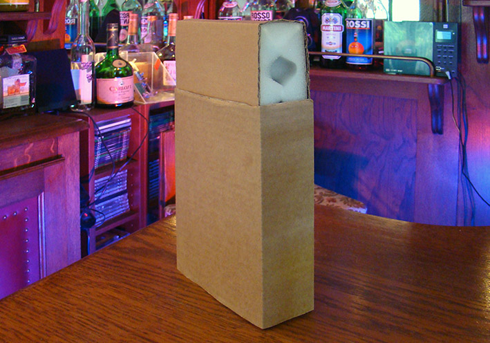 (08 Fold and push in.JPG) (08 Fold and push in.JPG)
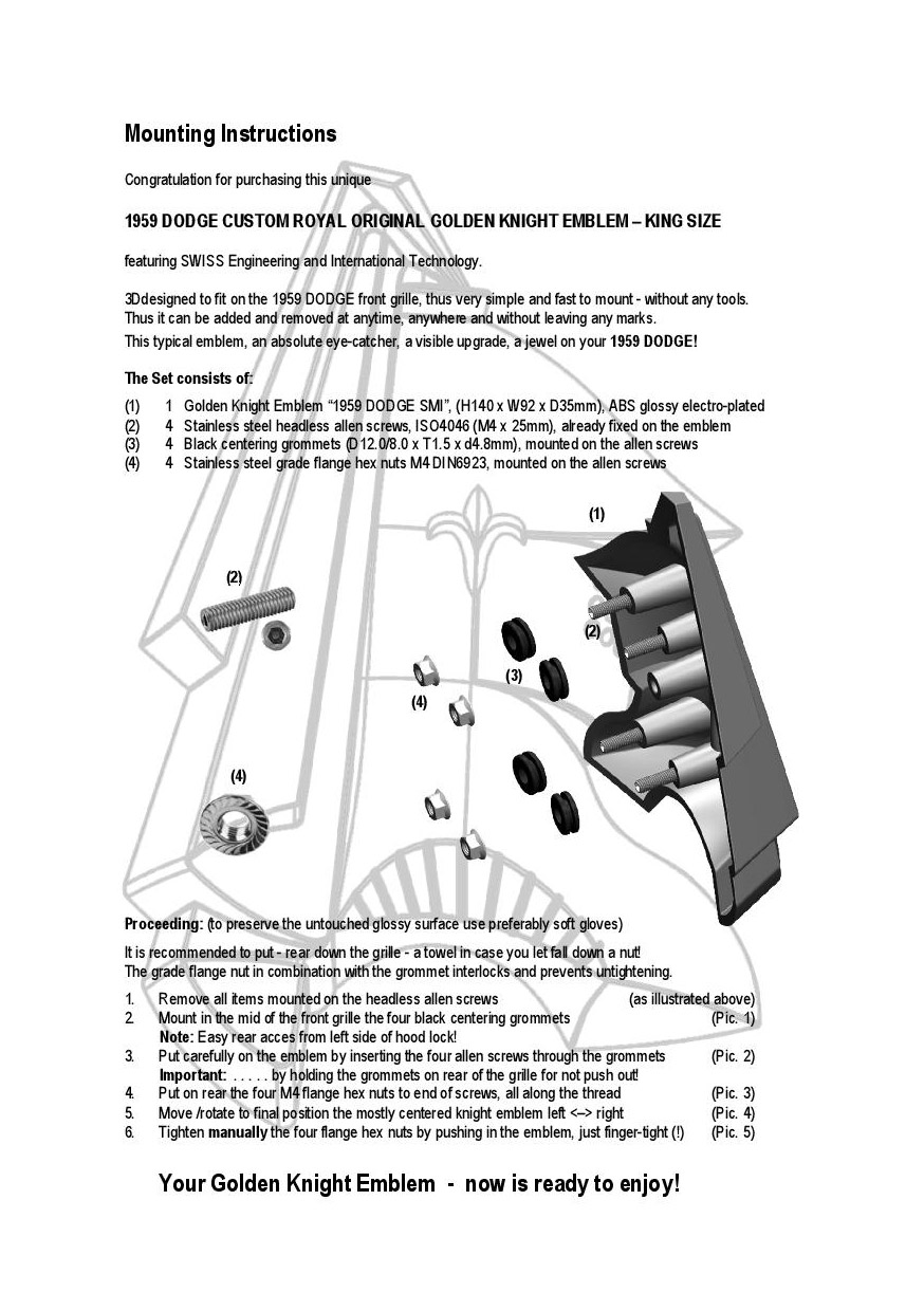 (09 Instructions 1959 DODGE CUSTOM ROYAL GOLDEN KNIGHT EMBLEM 01.jpg) (09 Instructions 1959 DODGE CUSTOM ROYAL GOLDEN KNIGHT EMBLEM 01.jpg)
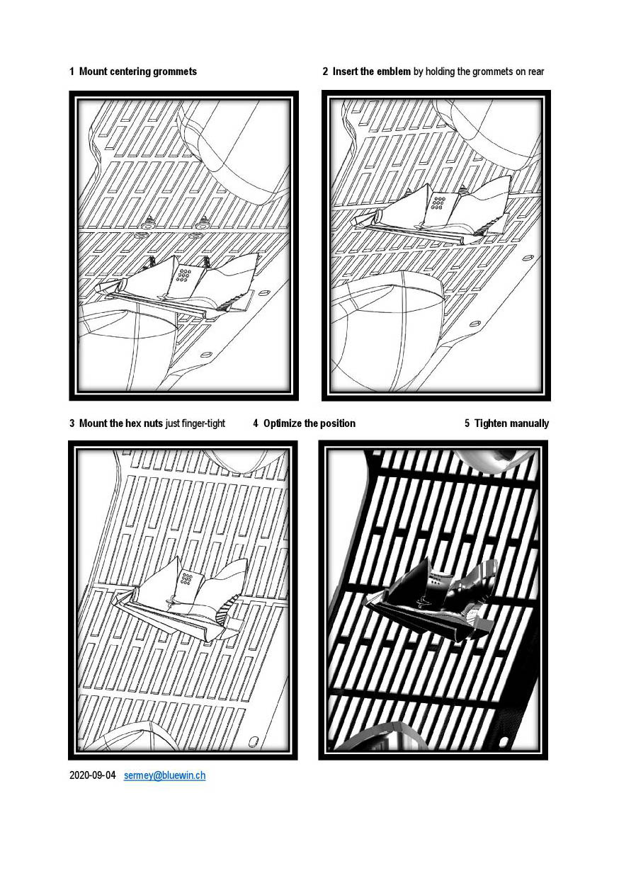 (10 Instructions 1959 DODGE CUSTOM ROYAL GOLDEN KNIGHT EMBLEM 02.jpg) (10 Instructions 1959 DODGE CUSTOM ROYAL GOLDEN KNIGHT EMBLEM 02.jpg)
Attachments
----------------
01 Gold on Original Front.jpg (197KB - 384 downloads)
02 Chrome on Original Front.jpg (160KB - 418 downloads)
03 Gold on SM Front.jpg (171KB - 395 downloads)
04 Check Glossy Surface.jpg (104KB - 398 downloads)
05 Silver Rear View Solo.jpg (106KB - 402 downloads)
06 Dual Rear 3D-Print - Chrome.jpg (90KB - 396 downloads)
07 Shipment Box.JPG (186KB - 396 downloads)
08 Fold and push in.JPG (146KB - 399 downloads)
09 Instructions 1959 DODGE CUSTOM ROYAL GOLDEN KNIGHT EMBLEM 01.jpg (215KB - 395 downloads)
10 Instructions 1959 DODGE CUSTOM ROYAL GOLDEN KNIGHT EMBLEM 02.jpg (221KB - 389 downloads)
|
|
| |
|
Elite Veteran
Posts: 682
Location: Finland | Hello Serge , this item makes me full of admiration! |
|
| |
|
Expert
Posts: 1215
Location: SWITZERLAND | Golden Coating: On a 1959 Dodge Custom Royal, Scripts and some knights are original already golden: the Lancer Fender Emblem NOS (1), the knight on the steering wheel NOS (2), the script Custom Royal (03). It is obvious that many owners as me, liked to have as well gold on all other knights. I purchased worldwide up to 20 various sprays, all promising real gold effect – all a disappointment! I had to do it by myself, many years ago. In addition to the new Golden Knight Emblem on front grille (glossy electro plated), previously presented, all other knights on the car should uniformly as well be golden. Here some golden coated samples on my car (4) to (13). Even the screws of the carburetors are golden (14). The aspect may vary according light and camera. What you see is mostly over 10 years old! Many times I have been asked for. Now, on special order, a set can be shipped combined in the same box as the Golden Knight Emblem (15). The quantity is limited. All details are summarized in the attached application (16). - SERGE - Another exclusivity for your outstanding 1959 Dodge!
Edited by sermey 2020-09-06 9:14 AM
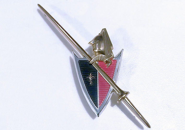 (01 Lancer Fender Emblem NOS.jpg) (01 Lancer Fender Emblem NOS.jpg)
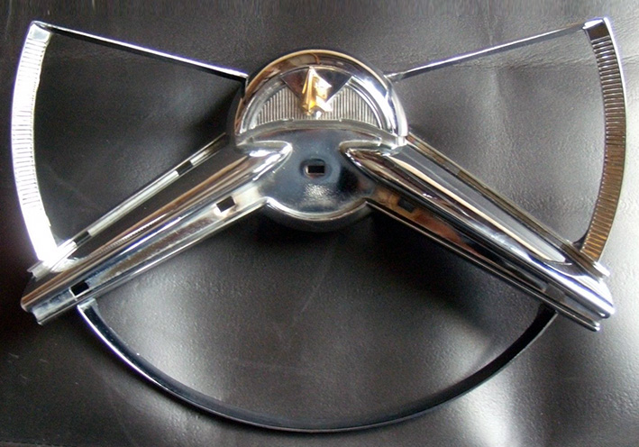 (02 Steering Wheel NOS.jpg) (02 Steering Wheel NOS.jpg)
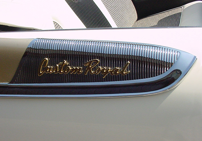 (03 Script Custom Royal.jpg) (03 Script Custom Royal.jpg)
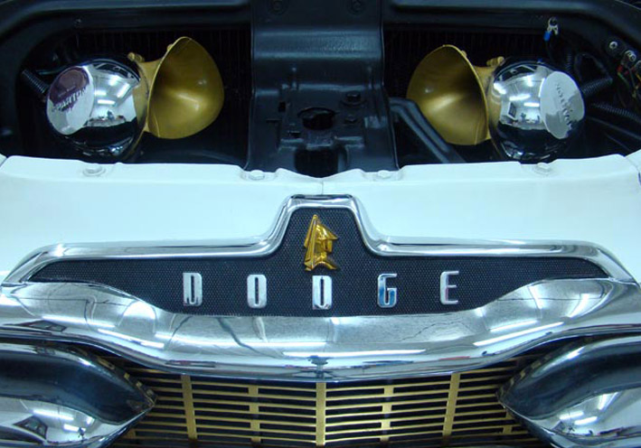 (04 Knight on Front Medaillon.jpg) (04 Knight on Front Medaillon.jpg)
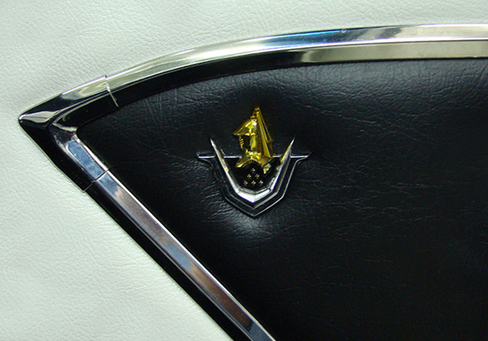 (05 Emblem on Door Panel.jpg) (05 Emblem on Door Panel.jpg)
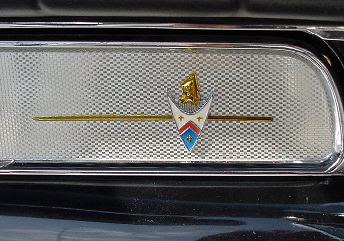 (06 Emblem on Glovebox.jpg) (06 Emblem on Glovebox.jpg)
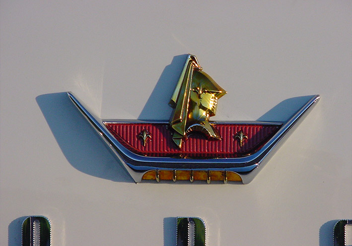 (07 Rear Trunk Emblem.jpg) (07 Rear Trunk Emblem.jpg)
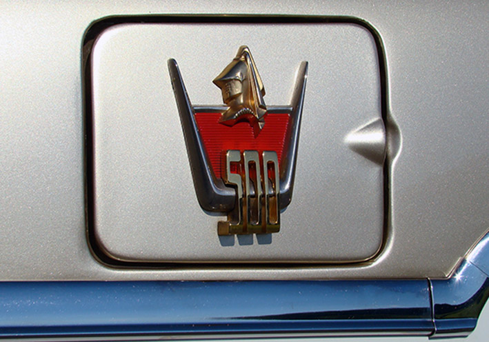 (08 D500 Emblem.jpg) (08 D500 Emblem.jpg)
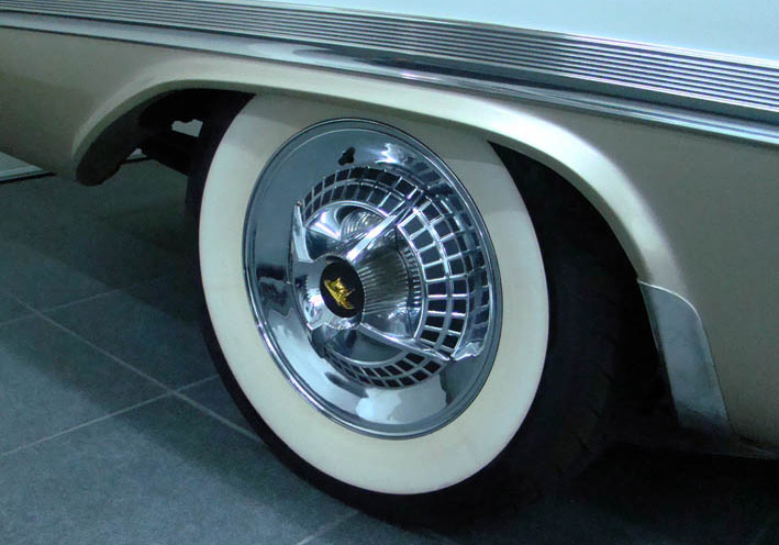 (09 Knight on Wheel Cover.jpg) (09 Knight on Wheel Cover.jpg)
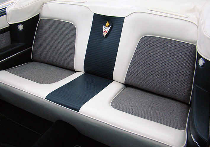 (10 Unique Emblem.jpg) (10 Unique Emblem.jpg)
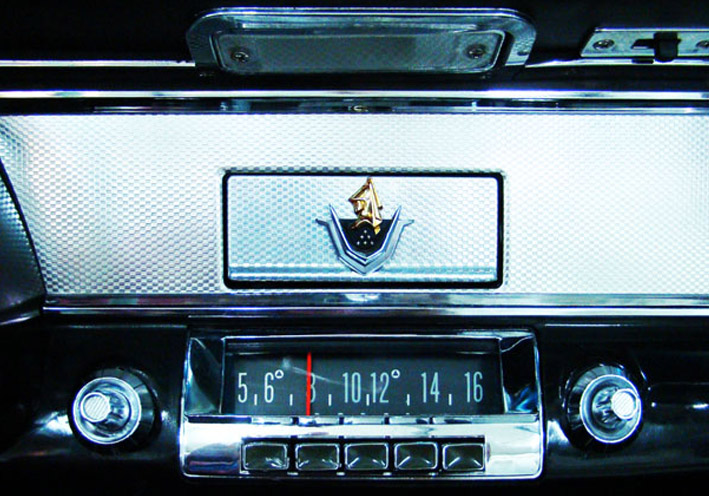 (11 Emblem on Ash Tray.jpg) (11 Emblem on Ash Tray.jpg)
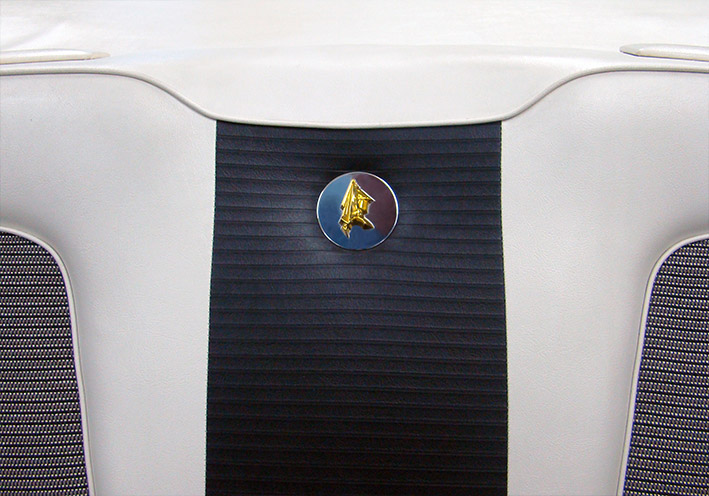 (12 Round Center Emblem.jpg) (12 Round Center Emblem.jpg)
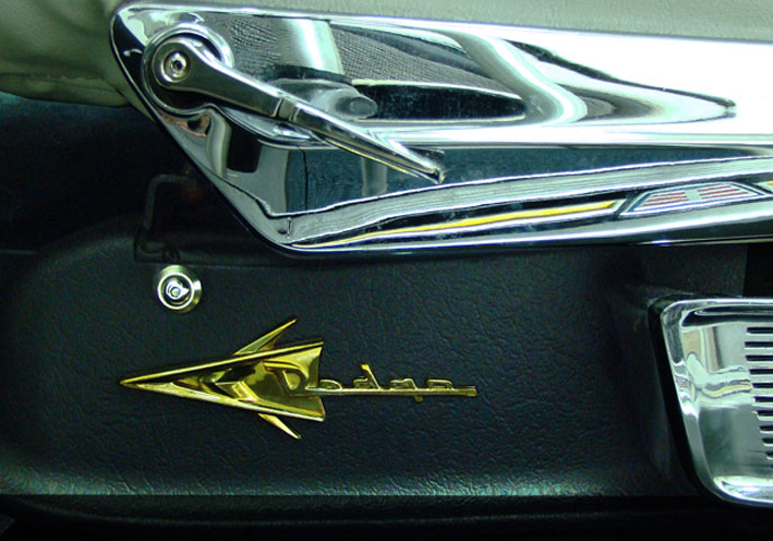 (13 Dodge FWL Emblem.jpg) (13 Dodge FWL Emblem.jpg)
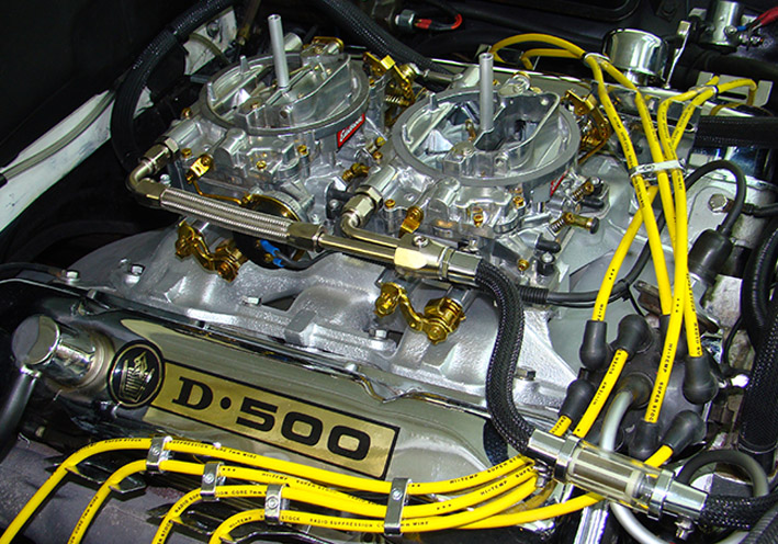 (14 Screws on Carburetors.jpg) (14 Screws on Carburetors.jpg)
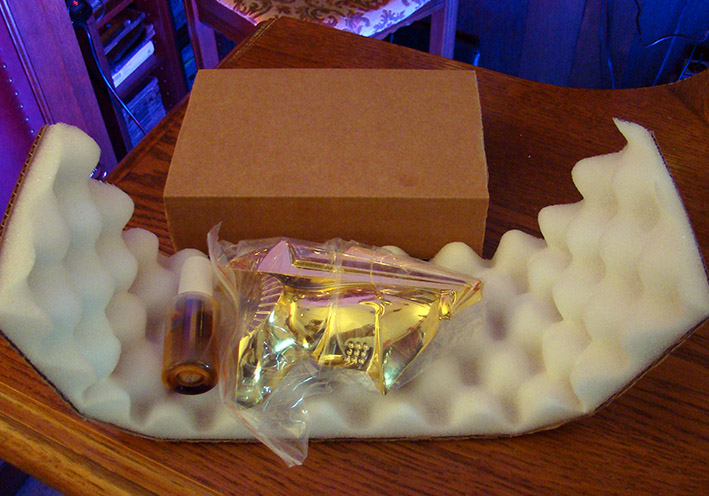 (15 Combined Shipment.jpg) (15 Combined Shipment.jpg)
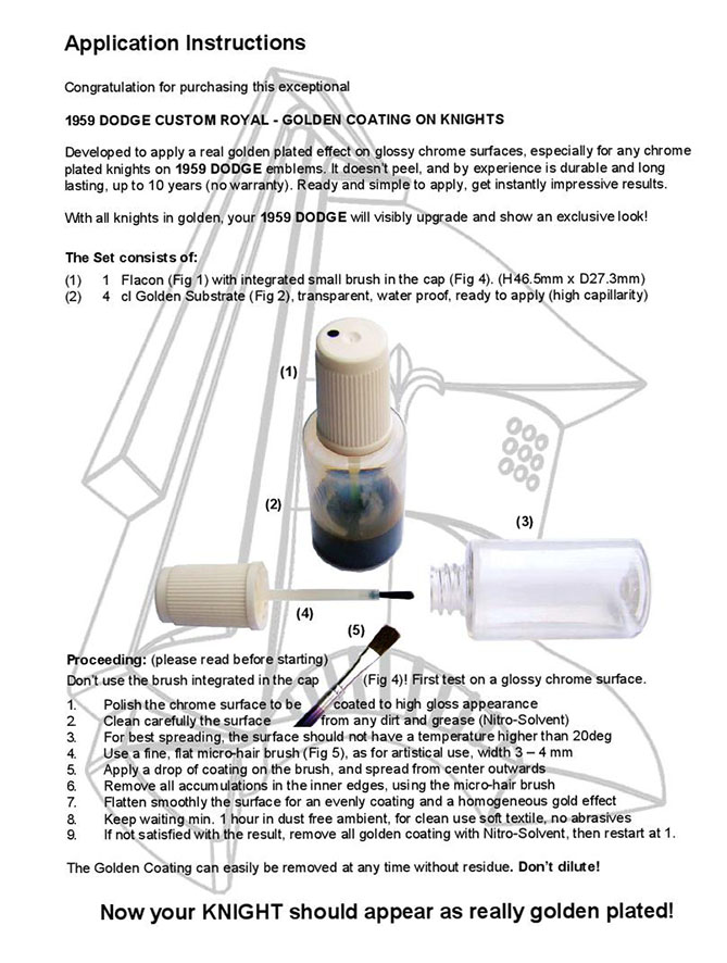 (16 Application Golden Coating.jpg) (16 Application Golden Coating.jpg)
Attachments
----------------
01 Lancer Fender Emblem NOS.jpg (113KB - 400 downloads)
02 Steering Wheel NOS.jpg (167KB - 386 downloads)
03 Script Custom Royal.jpg (123KB - 409 downloads)
04 Knight on Front Medaillon.jpg (128KB - 393 downloads)
05 Emblem on Door Panel.jpg (120KB - 397 downloads)
06 Emblem on Glovebox.jpg (161KB - 396 downloads)
07 Rear Trunk Emblem.jpg (95KB - 402 downloads)
08 D500 Emblem.jpg (130KB - 388 downloads)
09 Knight on Wheel Cover.jpg (111KB - 409 downloads)
10 Unique Emblem.jpg (126KB - 391 downloads)
11 Emblem on Ash Tray.jpg (153KB - 395 downloads)
12 Round Center Emblem.jpg (128KB - 391 downloads)
13 Dodge FWL Emblem.jpg (134KB - 404 downloads)
14 Screws on Carburetors.jpg (214KB - 387 downloads)
15 Combined Shipment.jpg (140KB - 401 downloads)
16 Application Golden Coating.jpg (157KB - 393 downloads)
|
|
| |
|
Expert
Posts: 1215
Location: SWITZERLAND | Bullets for Rear View Mirror2: Bullets in metal have been presented earlier in this thread. http://forwardlook.net/forums/forums/thread-view.asp?tid=23691&start=128 They are not only very nice when mounted (01), but the metal point is rated as dangerous in a case of collision. The logic conclusion is to replace them by rubber bullets: - Take small rubber bumpers, L15mm x D15mm x M4, they fit exatly to the mirrors diameter (02) - Grind them down to your preferred shape using a portable drilling machine (03) - Remove the metal bullets and mount the rubber bullets - done! (04) As the two bullet types are interchangeable (05), one set is kept in the glove box for replace at any time. Of course, the mirror can as well instantly be restored to original (06).
Another "HighTech" solution? - SERGE - ;)
Edited by sermey 2020-09-17 6:17 AM
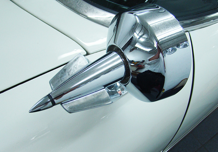 (01 Metal Bullet Mounted.JPG) (01 Metal Bullet Mounted.JPG)
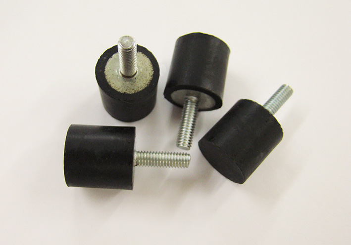 (02 Small Rubber Bumpers.JPG) (02 Small Rubber Bumpers.JPG)
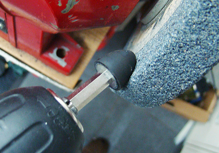 (03 Grinding the Rubber Bumper.JPG) (03 Grinding the Rubber Bumper.JPG)
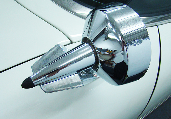 (04 Rubber Bullet Mounted.JPG) (04 Rubber Bullet Mounted.JPG)
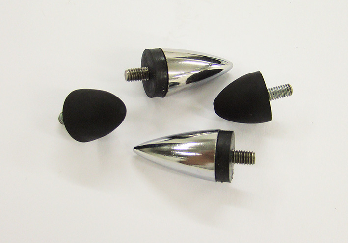 (05 Comparison Metal - Rubber.JPG) (05 Comparison Metal - Rubber.JPG)
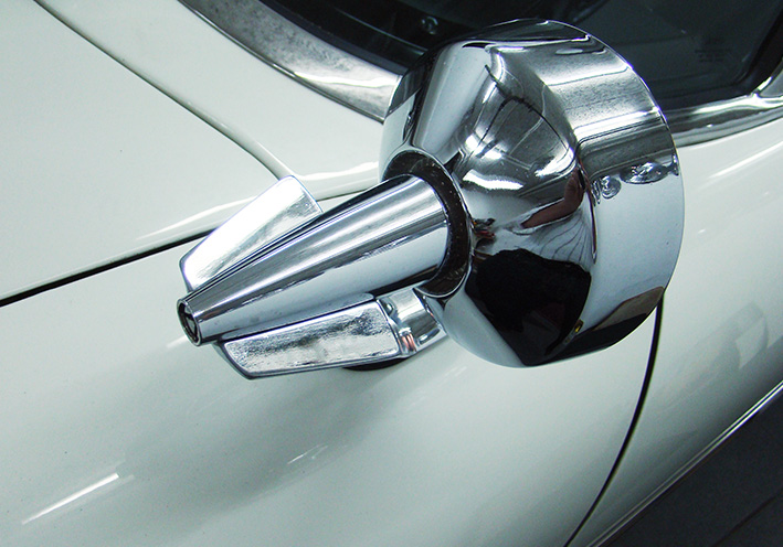 (06 Original Rear View Mirror.JPG) (06 Original Rear View Mirror.JPG)
Attachments
----------------
01 Metal Bullet Mounted.JPG (147KB - 442 downloads)
02 Small Rubber Bumpers.JPG (87KB - 427 downloads)
03 Grinding the Rubber Bumper.JPG (200KB - 421 downloads)
04 Rubber Bullet Mounted.JPG (154KB - 425 downloads)
05 Comparison Metal - Rubber.JPG (87KB - 440 downloads)
06 Original Rear View Mirror.JPG (154KB - 443 downloads)
|
|
| |
|
Expert
Posts: 1215
Location: SWITZERLAND | Danis Golden Knights: Today Dani (Daniel 1959) visited me with his recently acquired 1959 Dodge Custom Royal to pickup the ordered Golden Knight and a Set of Golden Coating. At place we mounted the Golden Knight, and to demonstrate how easy is to apply the Golden Coating the knight on the medaillon was instantly goldened (01). What a new feeling for the owner, now to drive with this visible upgraded car (02). At home he will as well golden coat all the other knights (emblems, wheel cover, . . .). Another applied "Make-up" of an outstanding 1959 Dodge Custom Royal. - SERGE -
Edited by sermey 2020-09-22 6:21 AM
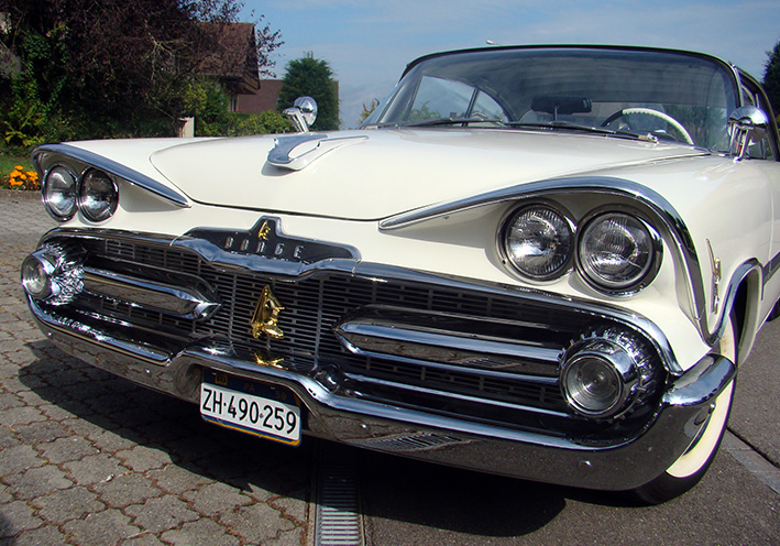 (01 Danis Golden Knights.JPG) (01 Danis Golden Knights.JPG)
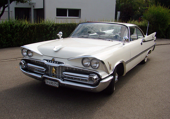 (02 Danis Golden Knights.JPG) (02 Danis Golden Knights.JPG)
Attachments
----------------
01 Danis Golden Knights.JPG (216KB - 441 downloads)
02 Danis Golden Knights.JPG (194KB - 438 downloads)
|
|
| |
|
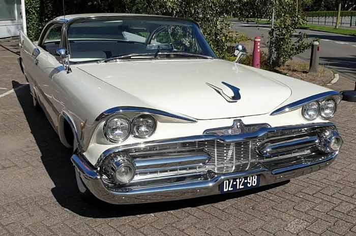
Regular
Posts: 57
Location: Switzerland | Thanks Serge, for your unique genius and outstanding work you have done by modelling this great upgrade "Golden Knight" for us Dodge enthusiasts now being available.
It's made of the highest quality automotive manufacturer standard ! What a great upgrade !
IMHO as if it was factory designed, ment to be there by the Dodge engineers. For me it fits perfectly to the car and surely increases the value.
Head turns are guaranteed !
Grateful
Dani |
|
| |
|
Expert
Posts: 1215
Location: SWITZERLAND | sermey - 2020-09-06 2:33 PM Golden Coating: . . . Many times I have been asked for. Now, on special order, a set can be shipped combined in the same box as the Golden Knight Emblem. . . I got multiple requests for stand-alone orders, for other cars or other purposes. I was thinking about have come to the decision to sell it ONLY together with a Big Knight: - Send alone is too risky because of the international restrictions (chemical items) - The reasonable amount doesn't comply to the extra effort for packing in a separate box, labeling, registering and bringing to post - I have about twenty of them, anyway not enough to satify the demand. Just enough for forward looking 1959 DODGE owners - Shipping together with the Golden Knight (on demand) is the same, the special box is safe, item can be declared as "repair kit" This special colloidal solutiion I mixed about 20 years ago for my own purpose, by adding various pigments, again and again . . . still to get the most authentic gold tone. Finally it accumulated up to 500cl. It doesn't peal, it doesn' crack, still looks golden after many years. - SERGE - :)
Edited by sermey 2020-09-23 12:47 PM
|
|
| |
|
Expert
Posts: 1215
Location: SWITZERLAND | Speedometer 4: The characteristic of the coil-spring determines the sensitivity of the instrument. The more weak the spring, the higher is the displayed value. The more strong, the lower will be the displayed value. The adjustment is shown on a speedometer of a 1959 Dodge. After remove the unit, the coil-spring is easily accessible from the side (01). Can state as well: The longer the active coil-spring, the softer it will be, the shorter then the stronger. By removing the splint-pin, the end of the coil-spring can be moved in for shortening, or out for extending the active lenght. To start, a difference of 2mm is recommended to estimate the final position. Mostly the speedometer shows rather a higher value, the length of the active coil-spring then should be shortened by pushing in the end (02 zoomed left). Don’t cut! Before testing, the zero position must be adjusted, as now this may have changed somewhat. Turn the entire spring unit using a needle as illustrated (02 zoomed right, and 03). The spring-coil should be kept absolute centered as shown! Now the speedometer is ready for a check. Zero correct setting for Dodge 1959 is shown in (04). It will need 2 – 3 attempts to find out the exact displayed value.
Notice: the diameter of the tires influences the speedometer and the odometer simultaneously. The odometer should prior shoukld be right and can only be adapted by changing the gear.
Another useful instruction. – SERGE –
Edited by sermey 2020-12-25 1:50 PM
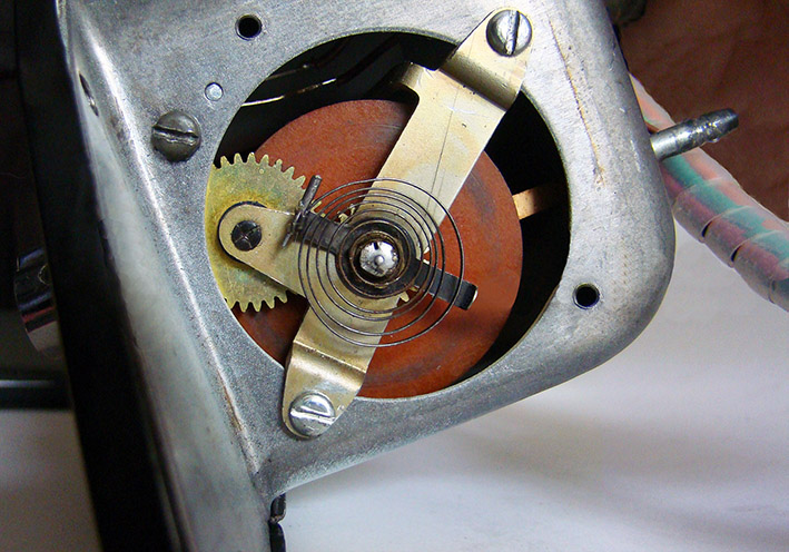 (01 Spring Assembly.jpg) (01 Spring Assembly.jpg)
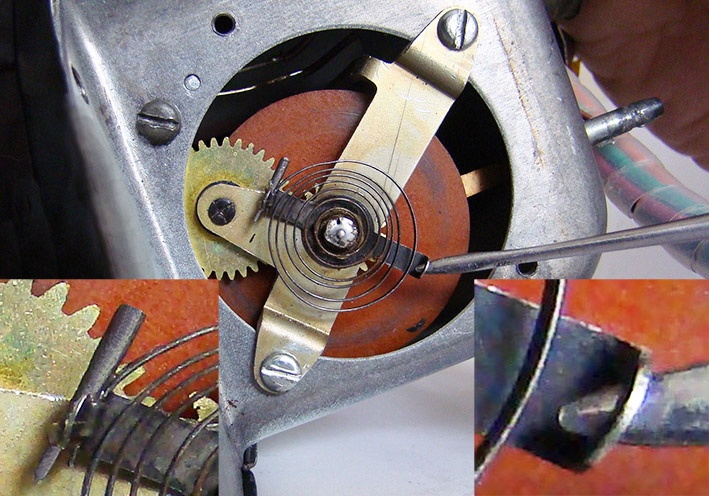 (02 Adjustments.jpg) (02 Adjustments.jpg)
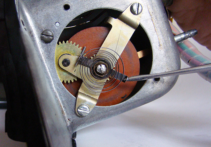 (03 Set Zero Position.jpg) (03 Set Zero Position.jpg)
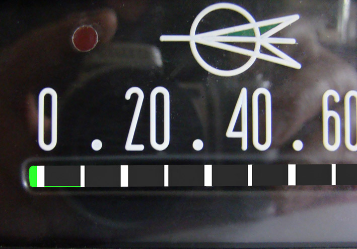 (04 1959 Dodge - Zero Correct Setting.jpg) (04 1959 Dodge - Zero Correct Setting.jpg)
Attachments
----------------
01 Spring Assembly.jpg (151KB - 386 downloads)
02 Adjustments.jpg (164KB - 411 downloads)
03 Set Zero Position.jpg (148KB - 398 downloads)
04 1959 Dodge - Zero Correct Setting.jpg (98KB - 386 downloads)
|
|
| |
|
Extreme Veteran
Posts: 446
Location: Beaumont TX | Hi Sid, It is a 1955 Plymouth Savoy.
Thanks for the instructions and pictures Serge. I have a much better understanding now. Will pull the speedometer when the weather warms up and see what is going on.
Thanks for everyone's help. |
|
| |
|
Expert
Posts: 1215
Location: SWITZERLAND | DAB+ Radio: Longtime I was thinking to implement DAB+ in my Original Radio (01). For this intended purpose I purchased another Spare Radio (02), and recently a small DAB+ Radio receiver (03). This receiver has 5 Control knobs according the Dodge radio (04). The LCD display fits well behind the front Radio glass (04). I found a DAB+ to FM Transmitter for instantly use (05), with an active adhesive antenna (06): Stick this antenna inside on the right corner of the windshield (07), invisible from on front view (08). Connect this device to the cigarette lighter (09). Then press for scan the DAB+ stations. On the FM-Radio select the transmitting frequency 87.6MHz by starting the station search, as just done on the transmitter. Now all DAB-Programs are available by the FM Radio. So far ready for a first functional check. This receiver/transmitter should be made invisible: it fits exactly in the left side of the glove box where the space is anyway unusable (10). Remove the main circuit box and disconnect the circuit board (11). Resold a cable extension 35 cm, leading its 5V supply (12). Instead of the cigarette adapter a Lighter Cable Adapter connected to 12V+ can be used (13). Or supply the circuit directly to the output of the 12V > 5V Step down Controller LM 7805CV (14). Anyway use 12V+ after the fuse and filter of the FM radio, then no other components are required. Fix the IC on the Radio body for cooling. Do another functional test. For mounting in the glove box, drill the center 28mm and 3 additional holes 4.5mm, according the M4 screws on the rear cover of the circuit box (15). Then push-in the circuit box and fix it with M4 wing nuts. It seems, this DAB+ Transmitter was especially designed to fit in this Glove Box (16). All DAB+ stations are available at full FM sound quality. Now I can listen to my preferred DAB+ SWISS POP station, non-stop music without any comment. DAB+ Radio another option for most FWL-Cars 1957 – 1959. - SERGE -
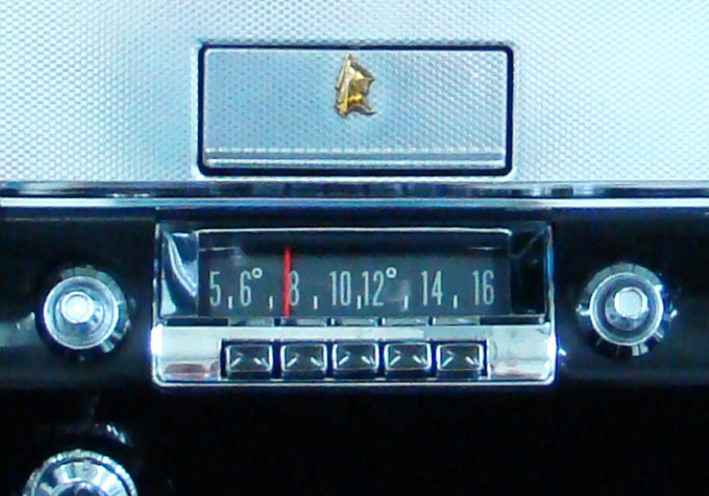 (01 1959 OR Radio.jpg) (01 1959 OR Radio.jpg)
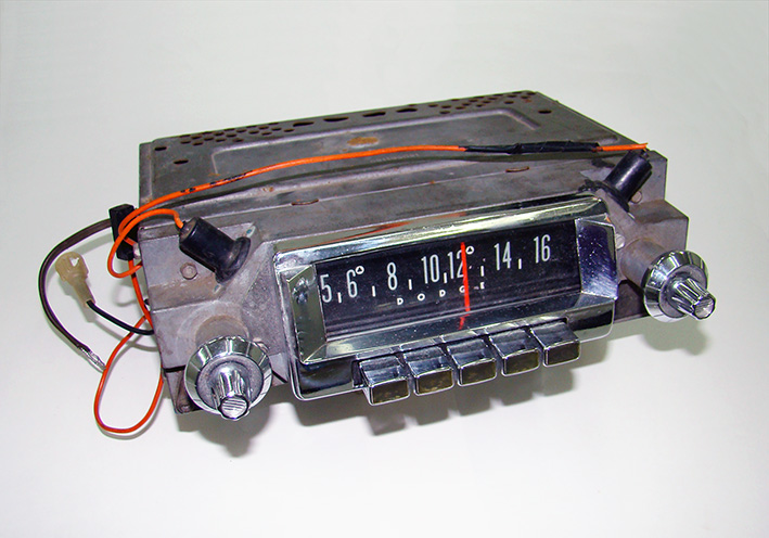 (02 1959 Spare Radio.jpg) (02 1959 Spare Radio.jpg)
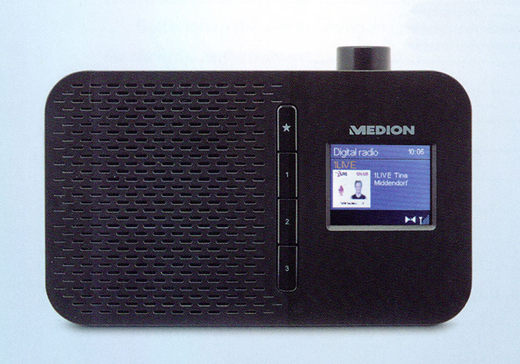 (03 Doc DAB+ Radio.jpg) (03 Doc DAB+ Radio.jpg)
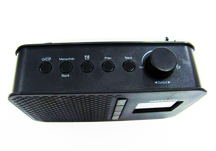 (04 DAB+ Radio Controls.jpg) (04 DAB+ Radio Controls.jpg)
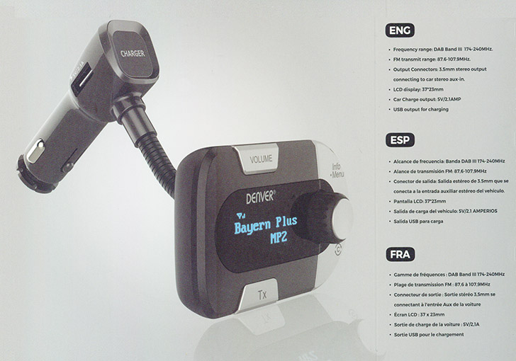 (05 Doc DAB+ to FM Transmitter.jpg) (05 Doc DAB+ to FM Transmitter.jpg)
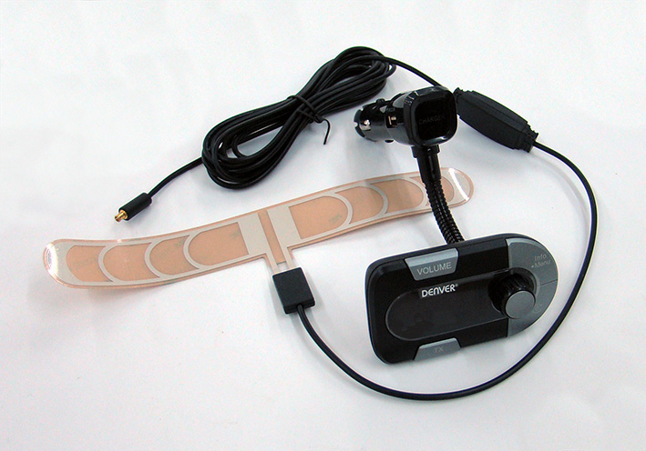 (06 Content with Active Antenna.jpg) (06 Content with Active Antenna.jpg)
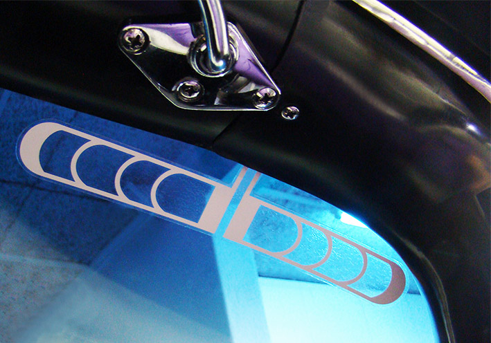 (07 Active Antenna Sticked.jpg) (07 Active Antenna Sticked.jpg)
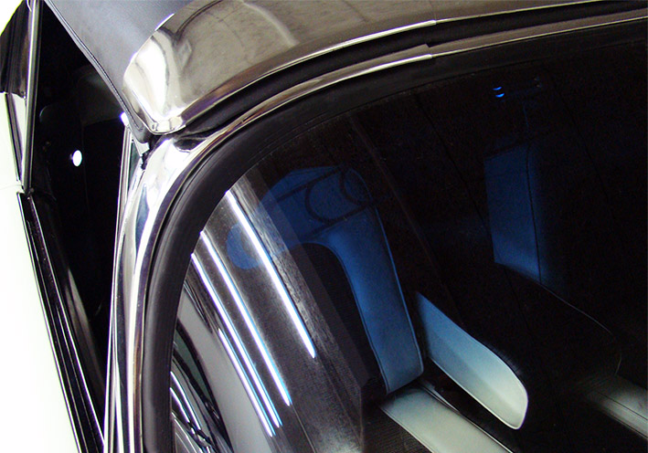 (08 Active Antenna Front View.jpg) (08 Active Antenna Front View.jpg)
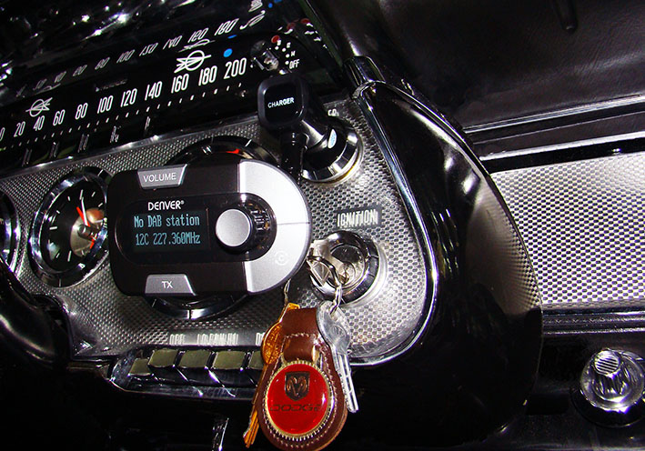 (09 DAB+ Transmitter Connected.jpg) (09 DAB+ Transmitter Connected.jpg)
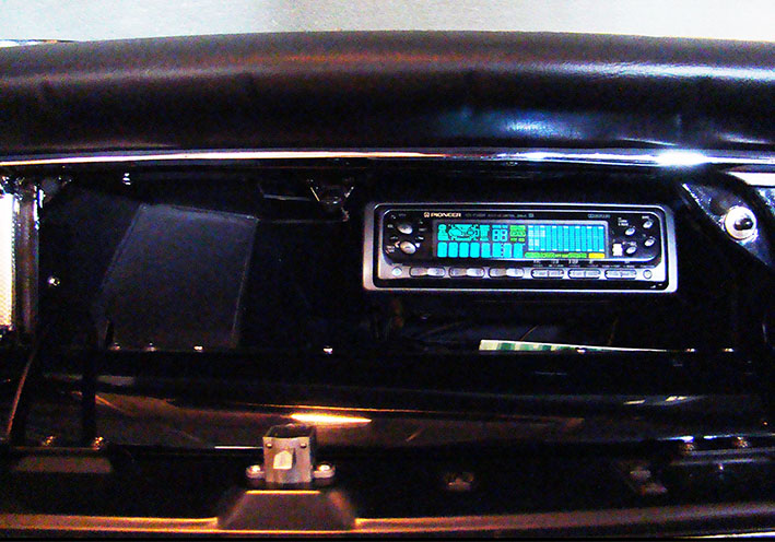 (10 Left Side of the Glove Box.jpg) (10 Left Side of the Glove Box.jpg)
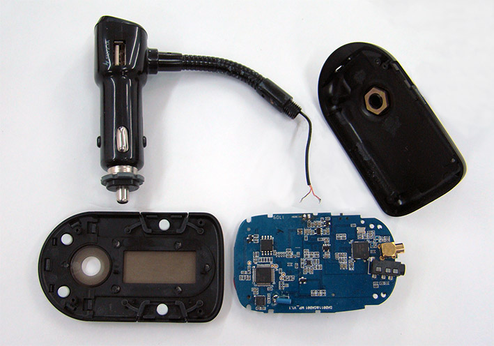 (11 Circuit Board Disconnected.JPG) (11 Circuit Board Disconnected.JPG)
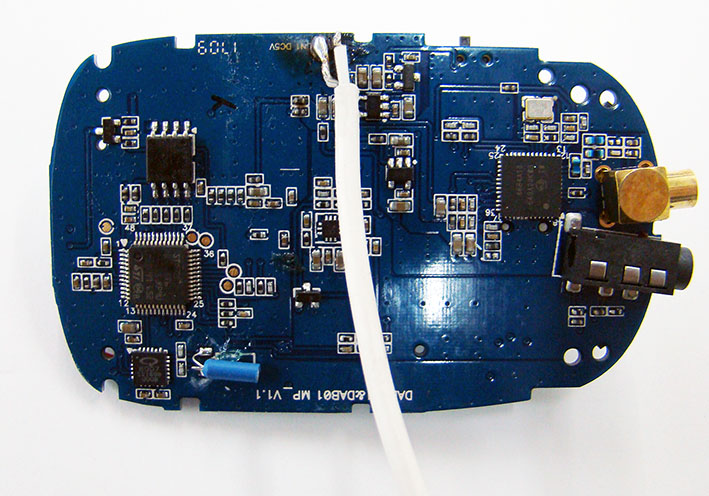 (12 New Cabel Extension.jpg) (12 New Cabel Extension.jpg)
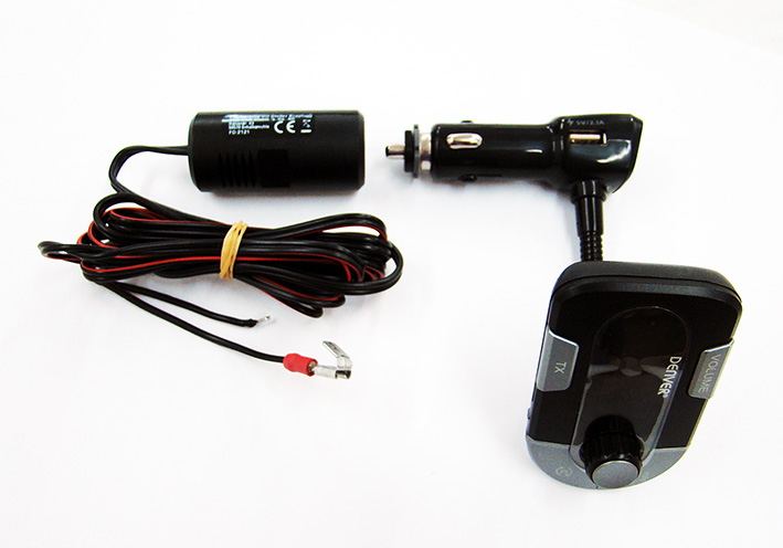 (13 Lighter Cable Adapter.jpg) (13 Lighter Cable Adapter.jpg)
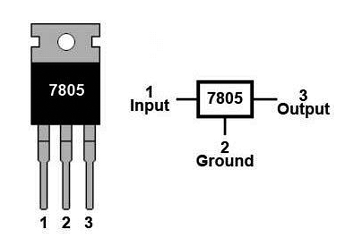 (14 Voltage Controller L7805CV.jpg) (14 Voltage Controller L7805CV.jpg)
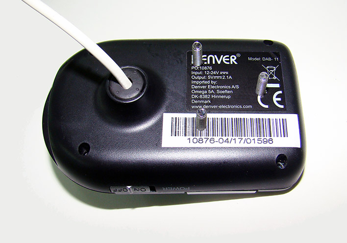 (15 Mounting M4 Screws.jpg) (15 Mounting M4 Screws.jpg)
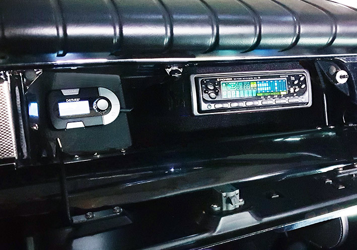 (16 DAB+ Final View.jpg) (16 DAB+ Final View.jpg)
Attachments
----------------
01 1959 OR Radio.jpg (150KB - 236 downloads)
02 1959 Spare Radio.jpg (142KB - 231 downloads)
03 Doc DAB+ Radio.jpg (139KB - 234 downloads)
04 DAB+ Radio Controls.jpg (134KB - 225 downloads)
05 Doc DAB+ to FM Transmitter.jpg (97KB - 237 downloads)
06 Content with Active Antenna.jpg (140KB - 228 downloads)
07 Active Antenna Sticked.jpg (137KB - 231 downloads)
08 Active Antenna Front View.jpg (134KB - 229 downloads)
09 DAB+ Transmitter Connected.jpg (156KB - 239 downloads)
10 Left Side of the Glove Box.jpg (124KB - 238 downloads)
11 Circuit Board Disconnected.JPG (104KB - 231 downloads)
12 New Cabel Extension.jpg (130KB - 232 downloads)
13 Lighter Cable Adapter.jpg (90KB - 231 downloads)
14 Voltage Controller L7805CV.jpg (67KB - 239 downloads)
15 Mounting M4 Screws.jpg (101KB - 233 downloads)
16 DAB+ Final View.jpg (137KB - 230 downloads)
|
|
| |
|
Expert
Posts: 1215
Location: SWITZERLAND | Power Door Locks: This is an option for comfort, already presented in this thread: http://www.forwardlook.net/forums/forums/thread-view.asp?tid=23691&start=64 Both doors are activated simultaneously, By the key from outside, or by the inside door handle. Just missing a separate control inside the car for the passengers. Now I found a Mopar Power Door Lock Switch matching optically to the 1959 Dodge (01) (02). Unfortunately, it is designed for vacuum operation (03). The disassembled parts are shown in Pic. (04). As my Power Locks are electric driven, this device had to be transformed to an electric switch. Just use appropriate insulating conducts and contacts (05) (06), then the electric function can simply be realised. Once more unfortunately: the available gap between radio and front is limited to 15mm. The switch must be reduced in height down to 14mm, keeping its full switching functionality. Even the upper edge needed to be rounded for a free positioning (07). The shifting solenoids in the two doors are linked with two control wires, one wire for UP = UNLOCK, the other wire for DOWN = LOCK, alternatively switched to ground, as does the modified switch. Just connect the Power Lock Switch to these two wires – done (08). No vacuum hoses, no vacuum leaks at all! The best position of the Door Lock Switch is on the center of the dashboard, below the radio, and turned for vertical up <–> down toggling (09). Now, the Power Door Lock Switch appears as it had been there all the time (10). Acting smooth like a micro switch. If needed for safety, the doors can easy be locked by the driver as by the passenger. Another useful and exclusive feature on an outstanding 1959 Dodge. Not absolutely needed, but always nice to have and to look at (11). - SERGE - (Pic. 11: Car paint somewhat modified by the tinted windshield)
Edited by sermey 2022-09-22 5:34 AM
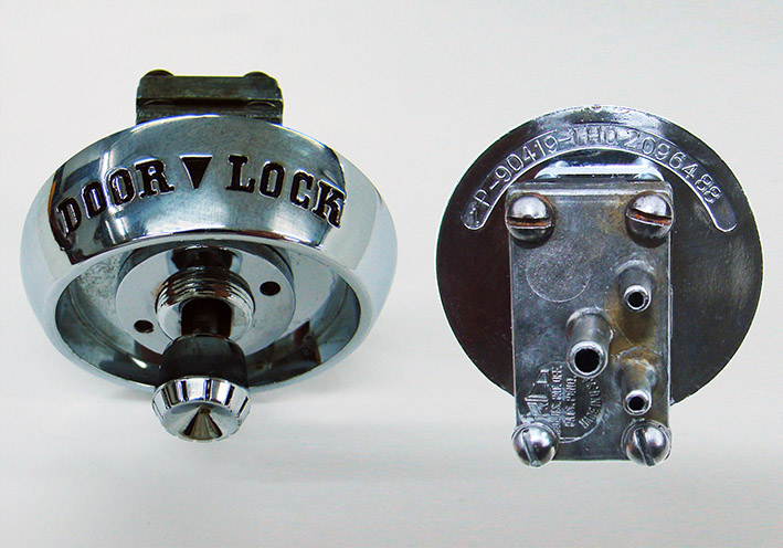 (01 Power Door Lock Switch.jpg) (01 Power Door Lock Switch.jpg)
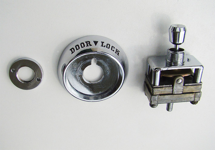 (02 Power Door Lock Switch.jpg) (02 Power Door Lock Switch.jpg)
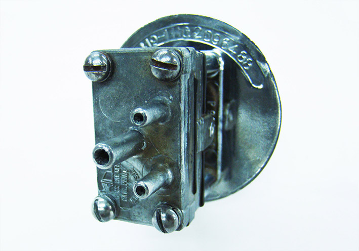 (03 Vacuum Operated.jpg) (03 Vacuum Operated.jpg)
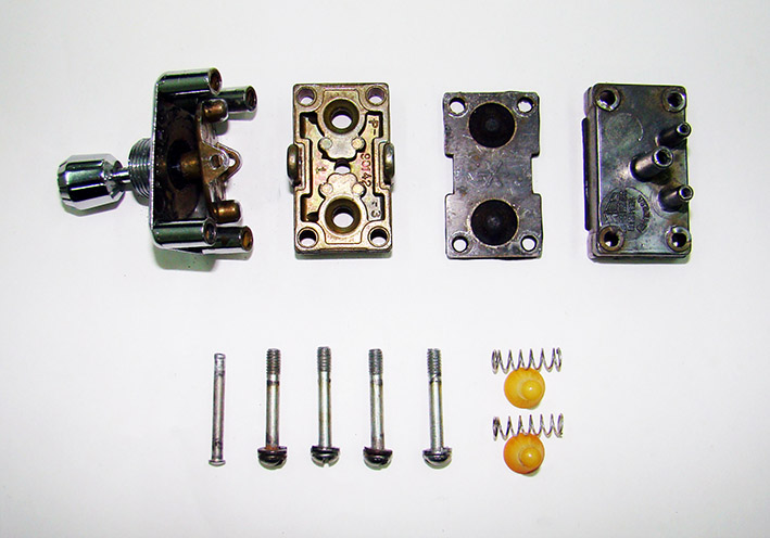 (04 Disassembled Switch.jpg) (04 Disassembled Switch.jpg)
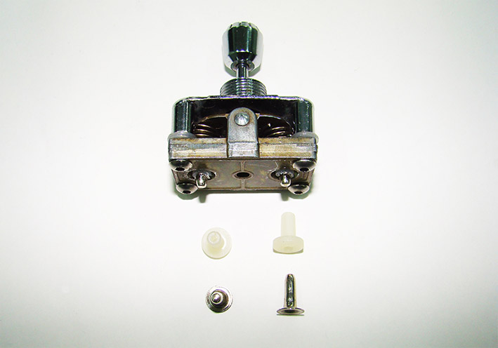 (05 Insulating Conducts and Contacts.jpg) (05 Insulating Conducts and Contacts.jpg)
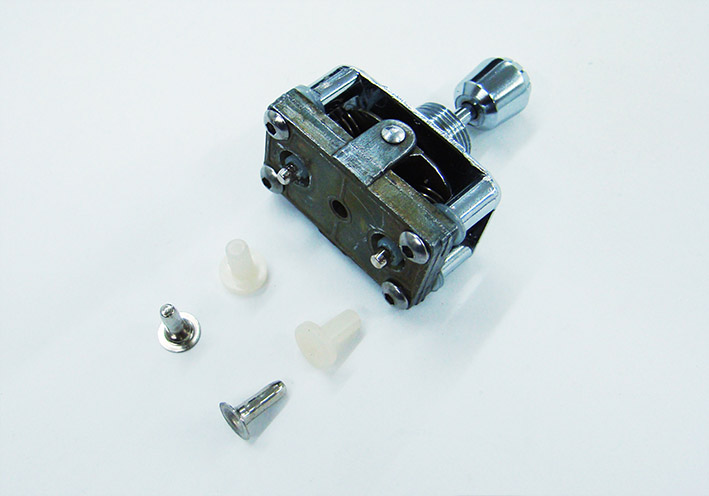 (06 Insulating Conducts and Contacts.jpg) (06 Insulating Conducts and Contacts.jpg)
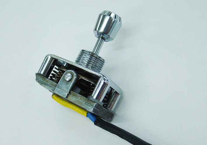 (07 New Height 14mm.jpg) (07 New Height 14mm.jpg)
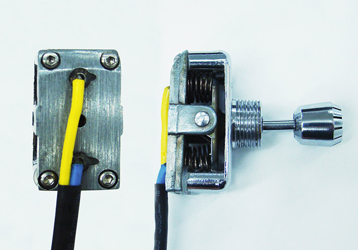 (08 Final Electric Switch.jpg) (08 Final Electric Switch.jpg)
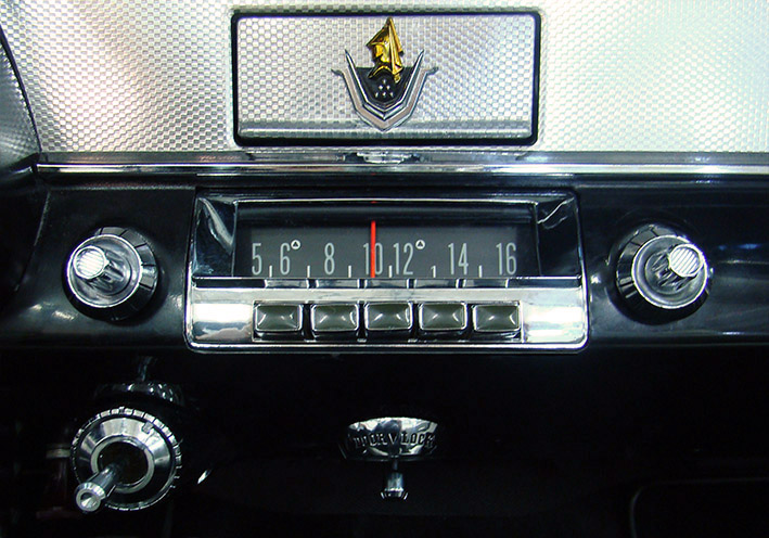 (09 Center Positioned FrontView.jpg) (09 Center Positioned FrontView.jpg)
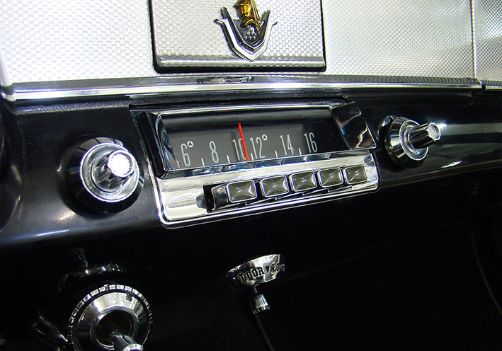 (10 Center Positioned SideView.jpg) (10 Center Positioned SideView.jpg)
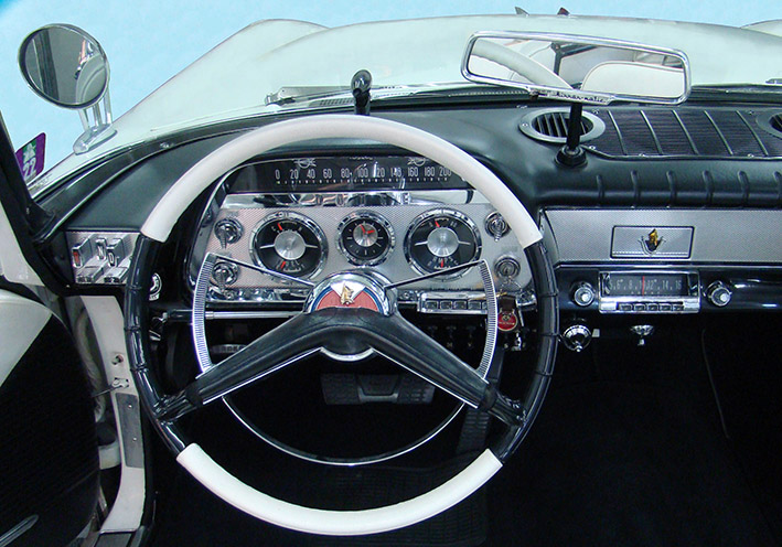 (11 Overview Instruments Panel.jpg) (11 Overview Instruments Panel.jpg)
Attachments
----------------
01 Power Door Lock Switch.jpg (124KB - 148 downloads)
02 Power Door Lock Switch.jpg (93KB - 140 downloads)
03 Vacuum Operated.jpg (95KB - 134 downloads)
04 Disassembled Switch.jpg (97KB - 132 downloads)
05 Insulating Conducts and Contacts.jpg (61KB - 141 downloads)
06 Insulating Conducts and Contacts.jpg (70KB - 139 downloads)
07 New Height 14mm.jpg (107KB - 142 downloads)
08 Final Electric Switch.jpg (97KB - 146 downloads)
09 Center Positioned FrontView.jpg (150KB - 140 downloads)
10 Center Positioned SideView.jpg (142KB - 136 downloads)
11 Overview Instruments Panel.jpg (157KB - 137 downloads)
|
|
| |
|
Expert
Posts: 1215
Location: SWITZERLAND | Metal Grid under Dash: Every time when working under the dash can see the multiple cables, partly floating and thus just visible from front (01). These are mostly accessory cables for radio, antenna, loudspeakers, power supplies, control wires and vacuum hoses.A mess under the glovebox (02), similar on left side near the FM-Radio (03). To hold them up without the use of binders, a black anodized Alu Grid Plate 50 x 20 cm 1mm can be used (04). It maintains the heating and air circulation due to the stretched structure (05). The appropriate contour is cut on a panel as template (06), then the grid plate accordingly (07). The border behind is slightly folded for stability (8mm), covered with a rubber profile (08) to protect from scratching the black carton. In addition this rubber holds the grid in the final position (09), no fixing elements needed at all (10). First hook in the front side, then shift up the other side as illustrated (11). The cables under the Glovebox, here before floating (12), now kept up after mounted (13). Not visible anymore from front – a neat solution (14). - SERGE -
Edited by sermey 2022-10-06 6:20 AM
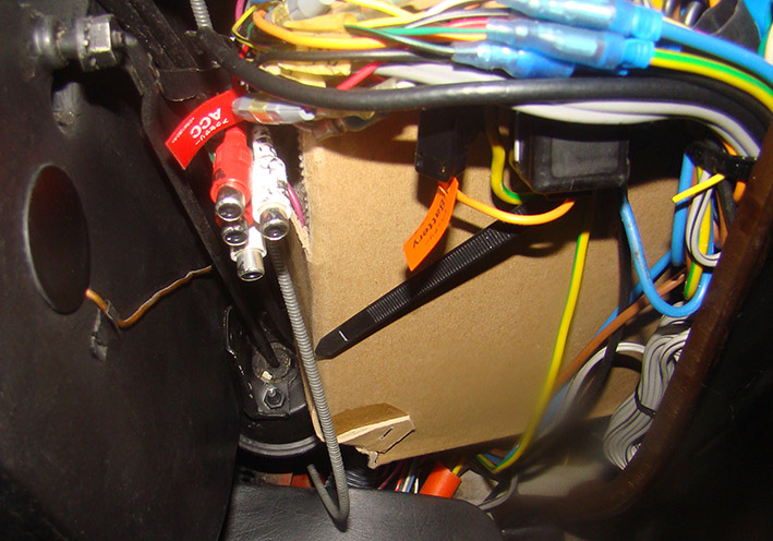 (01 Under the Glovebox.jpg) (01 Under the Glovebox.jpg)
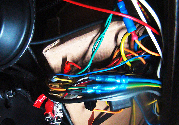 (02 Under the Glovebox.jpg) (02 Under the Glovebox.jpg)
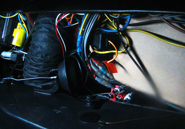 (03 Under Left beside FM-Radio.jpg) (03 Under Left beside FM-Radio.jpg)
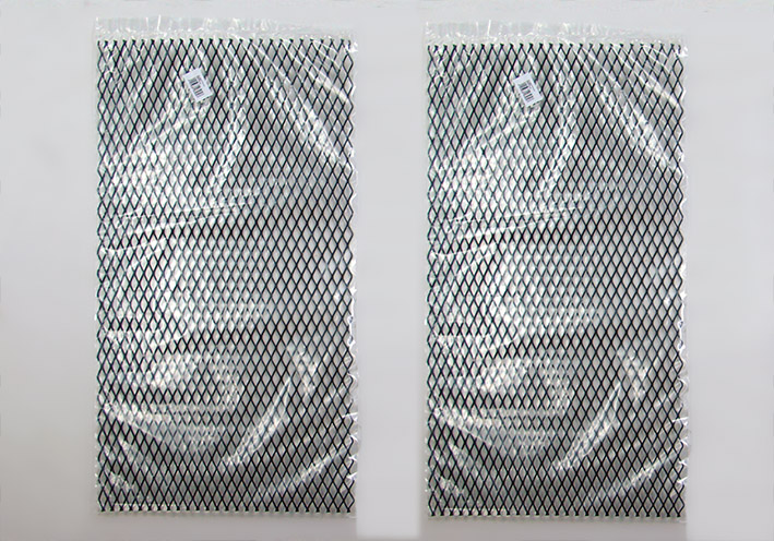 (04 Black Alu Grid Plate 50 x 20cm 1mm.jpg) (04 Black Alu Grid Plate 50 x 20cm 1mm.jpg)
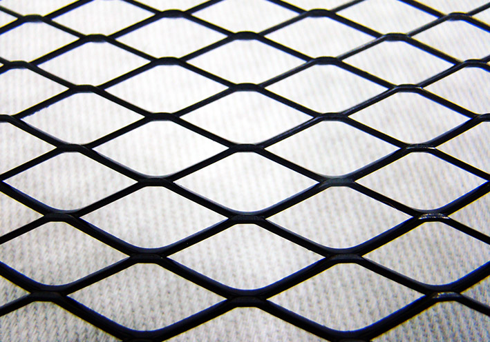 (05 Strechted Structure.jpg) (05 Strechted Structure.jpg)
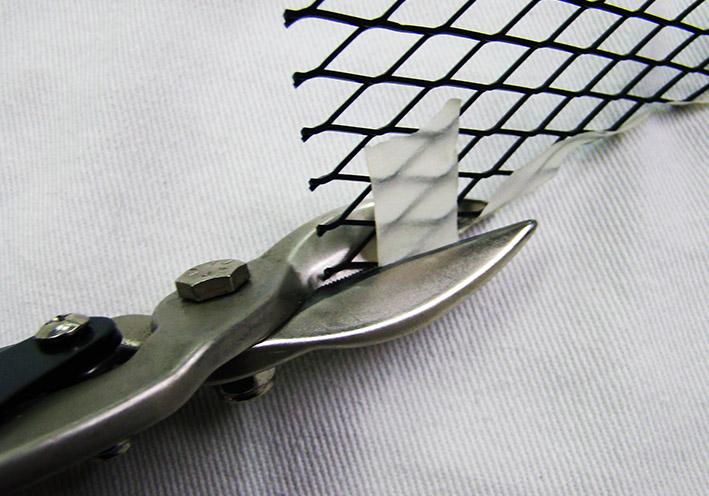 (06 Cutting the Plate.jpg) (06 Cutting the Plate.jpg)
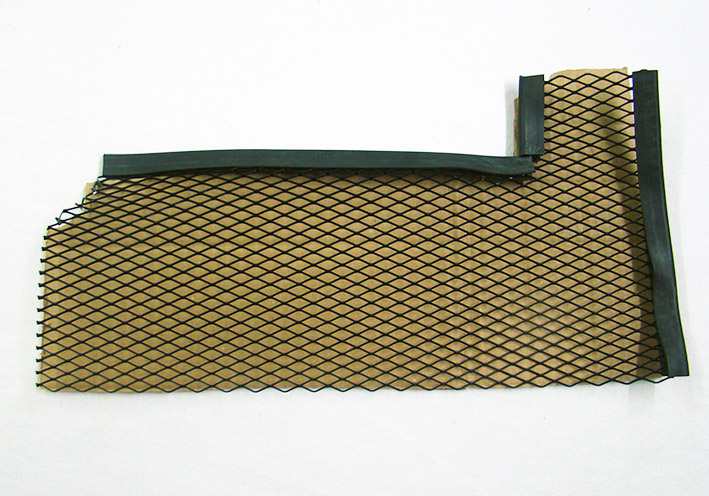 (07 Grid Plate Cut.jpg) (07 Grid Plate Cut.jpg)
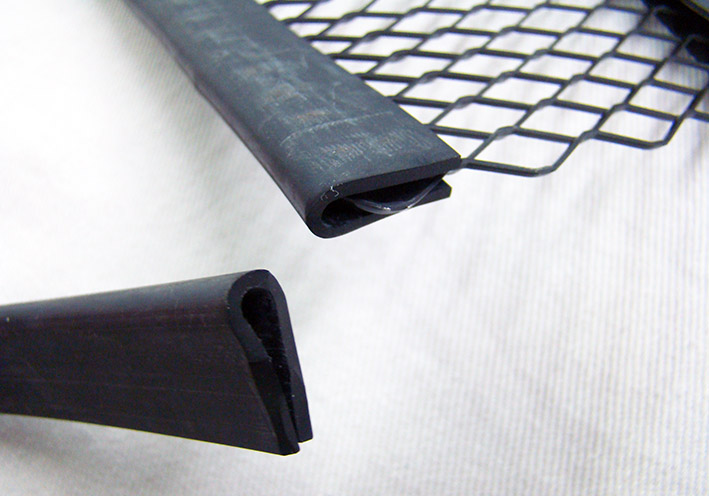 (08 Protection U-Profile.jpg) (08 Protection U-Profile.jpg)
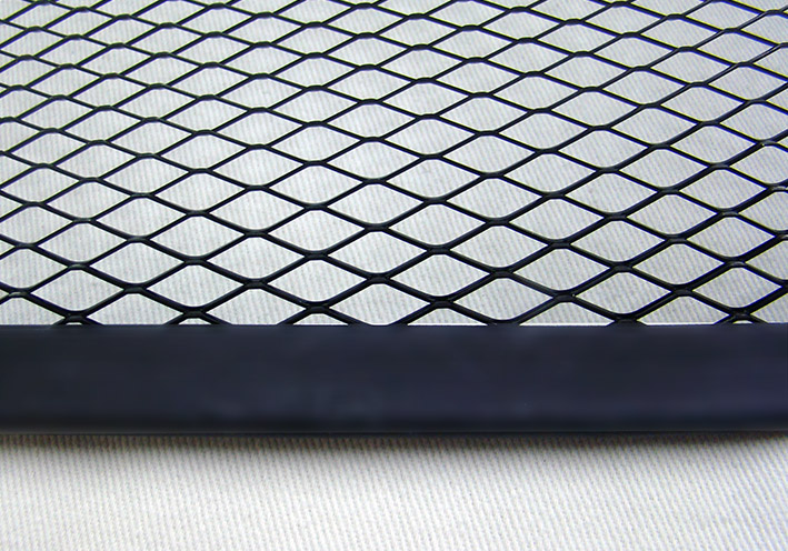 (09 Grid Border Protected.jpg) (09 Grid Border Protected.jpg)
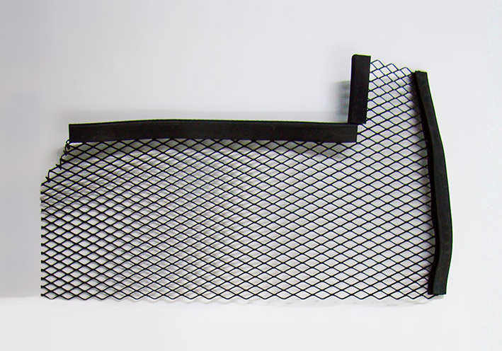 (10 Plate Ready for Mount.jpg) (10 Plate Ready for Mount.jpg)
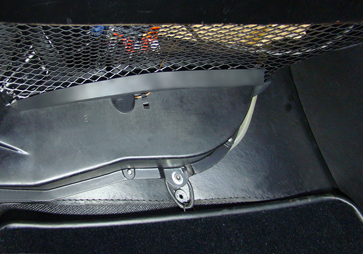 (11 Mounted FrontView.jpg) (11 Mounted FrontView.jpg)
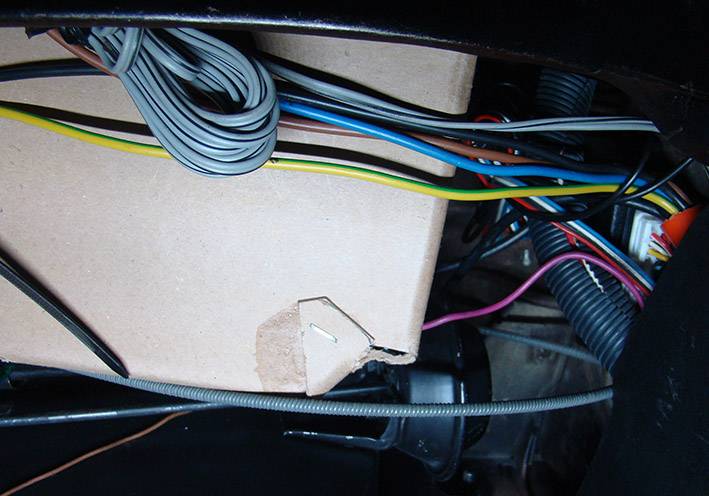 (12 Before mounted under the Glovebox.jpg) (12 Before mounted under the Glovebox.jpg)
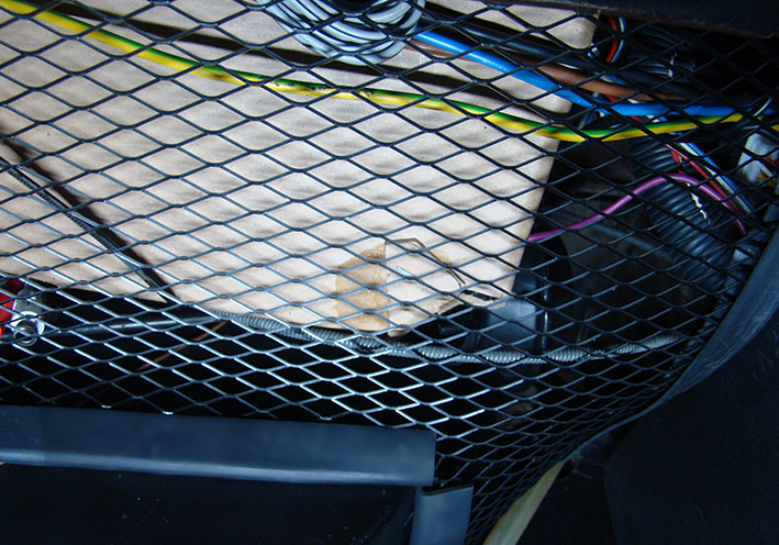 (13 After mounted under the Glovebox.jpg) (13 After mounted under the Glovebox.jpg)
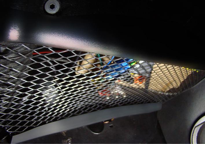 (14 Final Mounted SideView.jpg) (14 Final Mounted SideView.jpg)
Attachments
----------------
01 Under the Glovebox.jpg (145KB - 136 downloads)
02 Under the Glovebox.jpg (179KB - 131 downloads)
03 Under Left beside FM-Radio.jpg (166KB - 146 downloads)
04 Black Alu Grid Plate 50 x 20cm 1mm.jpg (196KB - 128 downloads)
05 Strechted Structure.jpg (170KB - 132 downloads)
06 Cutting the Plate.jpg (136KB - 140 downloads)
07 Grid Plate Cut.jpg (156KB - 142 downloads)
08 Protection U-Profile.jpg (101KB - 137 downloads)
09 Grid Border Protected.jpg (181KB - 132 downloads)
10 Plate Ready for Mount.jpg (152KB - 138 downloads)
11 Mounted FrontView.jpg (200KB - 132 downloads)
12 Before mounted under the Glovebox.jpg (137KB - 135 downloads)
13 After mounted under the Glovebox.jpg (189KB - 140 downloads)
14 Final Mounted SideView.jpg (163KB - 131 downloads)
|
|
| |
|
Expert
Posts: 1215
Location: SWITZERLAND | Replacing the Windshield: As the original bubble windshield had some deep impacts and showed a widely sandblasted surface, it had to be replaced (01). In addition, I wanted a green tinted glass, including the dark stripe on top. At the time a similar bubble glass replacement was not available. Simultaneously I switched all other car glasses to the same green tint, safety solex glass (04). After removing all fixing clips the windshield was pressed out from inside by the power of “four human legs“. Can also see the flawless finish of the surface (02). The new window seal was somewhat dicker and longer, could just not use. Whereas the old one had the exact length and shape, and was not brittle at all. This due to the lifetime garaged car. Best decision was to use this old seal, showing not any damages. Raze the old seal, using steel wool, to become black again. Then threat the surface with Glycerin, so as the seal get smooth and looks as new (03). Of course, this old seal was somewhat harder than the new one, but could easily mount, and at all fitted excellent. Pre-condition: must insert exact at the same position, applying lubricant and sealant in one, and use a string to overlap the windshield edges. A new windshield with the dark stripe on top, and all new tinted glasses, an absolute clear view all around (04). - SERGE -
Edited by sermey 2022-10-08 11:39 AM
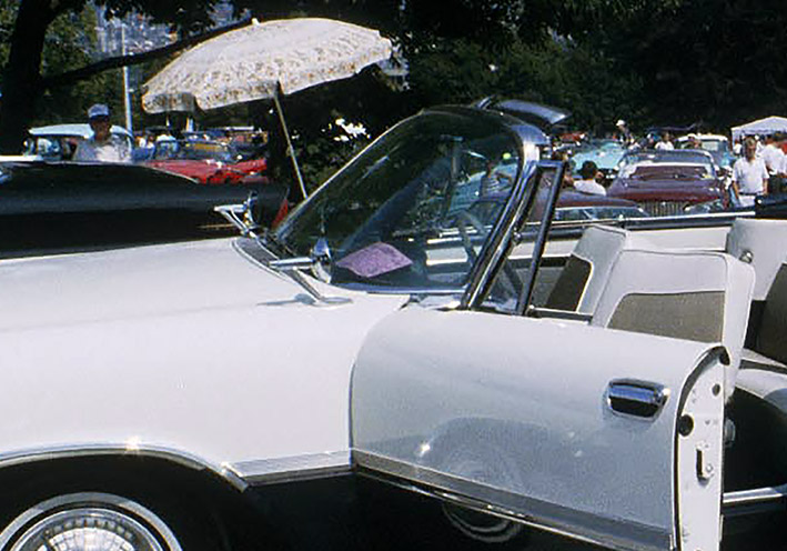 (01 Original Bubble Windshield.jpg) (01 Original Bubble Windshield.jpg)
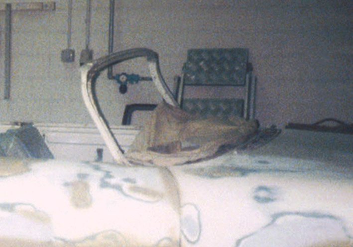 (02 Bubble Windshield removed.jpg) (02 Bubble Windshield removed.jpg)
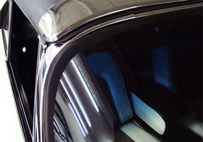 (03 Old Original Windshield Seal.jpg) (03 Old Original Windshield Seal.jpg)
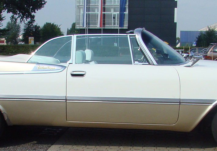 (04 All New Green Tinted Glasses.jpg) (04 All New Green Tinted Glasses.jpg)
Attachments
----------------
01 Original Bubble Windshield.jpg (123KB - 142 downloads)
02 Bubble Windshield removed.jpg (91KB - 136 downloads)
03 Old Original Windshield Seal.jpg (131KB - 137 downloads)
04 All New Green Tinted Glasses.jpg (107KB - 143 downloads)
|
|
| |
|
Expert
Posts: 1215
Location: SWITZERLAND | Cap MIRROR CONTROL: I found a remote mirror set with the cap MIRROR CONTROL, didn’t see before and missing in my car (01). When arrived it showed scratched and too wasted, couldn't repair better (02). I had to remake another cap. First model in 3D-RealView with engraved letters (03) (04), then 3D-Print in black, fill the letters in white (05) and hook up on the nut (06). Now the heavy chrome has reduced somewhat, the aspect more appealing (07). - SERGE - ;) N.B. The cap was printed in FDM-Technology. Will redo in SLA-Technology for much higher accuracy of the engraved letters. When done I will replace and present here.
Edited by sermey 2022-10-09 12:04 PM
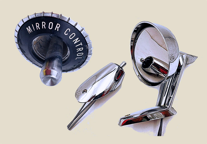 (01 Remote Mirror Set.jpg) (01 Remote Mirror Set.jpg)
 (02 Cap MIRROR CONTROL OR.jpg) (02 Cap MIRROR CONTROL OR.jpg)
 (03 Cap MIRROR CONTROL CAD.jpg) (03 Cap MIRROR CONTROL CAD.jpg)
 (04 Version Smaller Center CAD.jpg) (04 Version Smaller Center CAD.jpg)
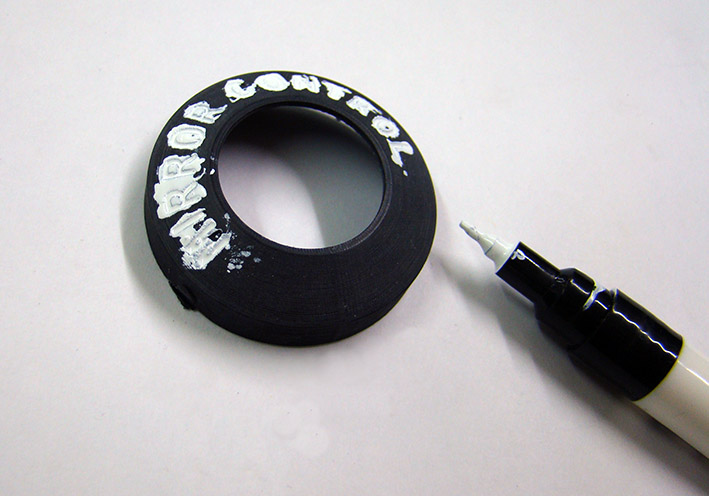 (05 Painting Letters on 3D-Print .jpg) (05 Painting Letters on 3D-Print .jpg)
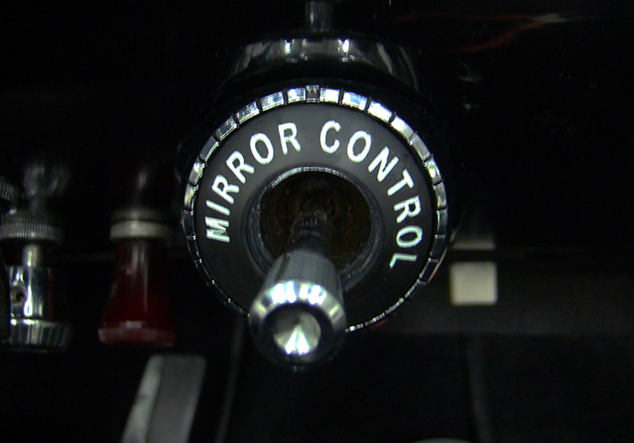 (06 Cap Hooked up.jpg) (06 Cap Hooked up.jpg)
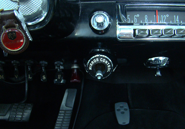 (07 Final Front View.jpg) (07 Final Front View.jpg)
Attachments
----------------
01 Remote Mirror Set.jpg (102KB - 176 downloads)
02 Cap MIRROR CONTROL OR.jpg (57KB - 165 downloads)
03 Cap MIRROR CONTROL CAD.jpg (95KB - 174 downloads)
04 Version Smaller Center CAD.jpg (69KB - 163 downloads)
05 Painting Letters on 3D-Print .jpg (90KB - 160 downloads)
06 Cap Hooked up.jpg (86KB - 167 downloads)
07 Final Front View.jpg (118KB - 158 downloads)
|
|
| |
|
Expert
Posts: 1215
Location: SWITZERLAND | Replacing the Windshield (Add-on): On special request here the full picture (05).
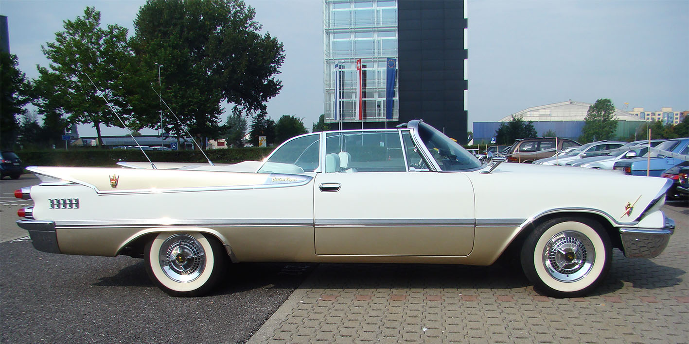 (05 All New Green Tinted Glasses.jpg) (05 All New Green Tinted Glasses.jpg)
Attachments
----------------
05 All New Green Tinted Glasses.jpg (236KB - 153 downloads)
|
|
| |
|
Expert
Posts: 1215
Location: SWITZERLAND | sermey - 2009-01-04 1:02 AM Rear Lamp Gaskets: No comments to the old / original Gasket. I found High Precision Hydraulic Rings, self-centering inside, outside not overlapping at all, and they fit as tailored. The black Height of 1/4" is a nice separation between the White Body and the Rechromed Housing. Another inconspicious "Make-Up". :) ________________________________________ Rear Lamp Gaskets Data Sheet: This High Precision Hydraulic Ring is no more available from the supplier. I found a similar Data Sheet as information (01) from another manufacturer. The costs are quite high for a gasket, as it needs 4 items for a 1959 Dodge. On the other hand this material is more durable than any rubber. The CAD design shows how the lip sets in center position of the housing (02), and how accurate this profile fits in size (03). Mounted on the car there is a decorative distance of 6mm (04). By tightening, the outer surface of the ring becomes slightly rounded, a desirable effect (05). - SERGE -
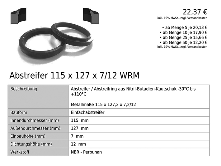 (01 Abstreifer Datenblatt.jpg) (01 Abstreifer Datenblatt.jpg)
 (02 Rear Lamp Gasket Profile CAD.jpg) (02 Rear Lamp Gasket Profile CAD.jpg)
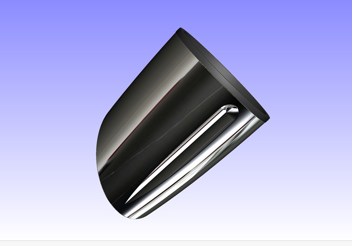 (03 Rear Lamp Gasket CAD.jpg) (03 Rear Lamp Gasket CAD.jpg)
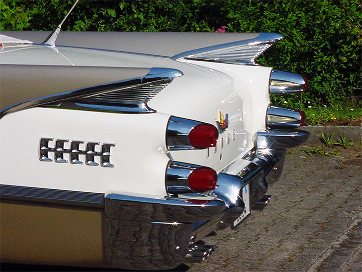 (04 Rear Lamp Gasket on Car.jpg) (04 Rear Lamp Gasket on Car.jpg)
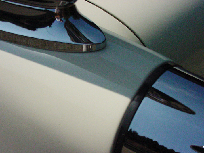 (05 Rear Lamp Gasket on Car Zoomed.jpg) (05 Rear Lamp Gasket on Car Zoomed.jpg)
Attachments
----------------
01 Abstreifer Datenblatt.jpg (131KB - 166 downloads)
02 Rear Lamp Gasket Profile CAD.jpg (51KB - 166 downloads)
03 Rear Lamp Gasket CAD.jpg (75KB - 150 downloads)
04 Rear Lamp Gasket on Car.jpg (179KB - 176 downloads)
05 Rear Lamp Gasket on Car Zoomed.jpg (159KB - 159 downloads)
|
|
| |
|
Expert
Posts: 1215
Location: SWITZERLAND | Convertible Top Down: Most Convertibles shows not correct setting of the top when down. Even on perfect restored cars of our challenging members (01) (02), the heighted top stands out, up to 10cm (03). This reminds the old fashioned “carriage” look on convertibles of earlier years (04). Before restoring, the top arm of my car was as well up (05). With some effort I adjusted the mechanics for fully entering in the side box. The end of the arm now touches the body, as it should be (06). View from side, camera horizontal lined to both door borders, the top arm almost disappears (07). Then the top cover is adapted correspondingly to fit. Now it shows very flat (08). Another harmonic car outline of designer Virgil Exner (09). – SERGE -
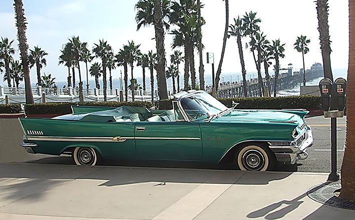 (01 Nice Convertible - Gary.jpg) (01 Nice Convertible - Gary.jpg)
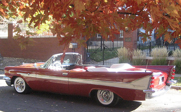 (02 Nice Convertible - Mike.jpg) (02 Nice Convertible - Mike.jpg)
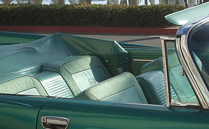 (03 Top not down - Gary.jpg) (03 Top not down - Gary.jpg)
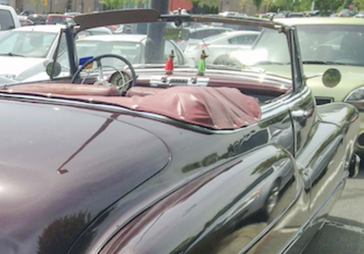 (04 Top earlier years.jpg) (04 Top earlier years.jpg)
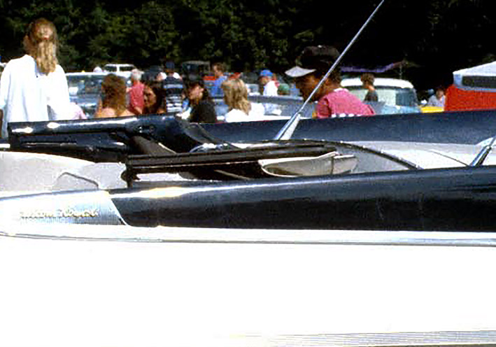 (05 My Convertible Before - Top Arm Up.jpg) (05 My Convertible Before - Top Arm Up.jpg)
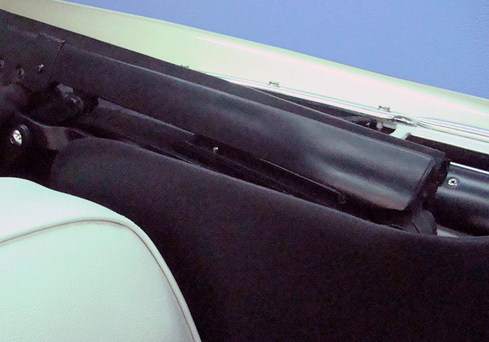 (06 My Convertible After - Top Arm down.jpg) (06 My Convertible After - Top Arm down.jpg)
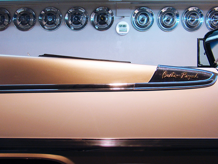 (07 View from Side.jpg) (07 View from Side.jpg)
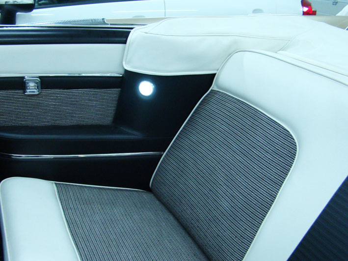 (08 Flat Top Cover.jpg) (08 Flat Top Cover.jpg)
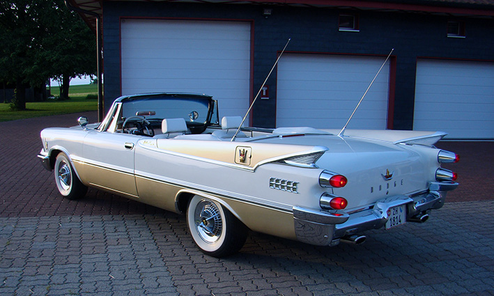 (09 Review the Convertible.jpg) (09 Review the Convertible.jpg)
Attachments
----------------
01 Nice Convertible - Gary.jpg (183KB - 144 downloads)
02 Nice Convertible - Mike.jpg (185KB - 168 downloads)
03 Top not down - Gary.jpg (183KB - 153 downloads)
04 Top earlier years.jpg (128KB - 155 downloads)
05 My Convertible Before - Top Arm Up.jpg (102KB - 148 downloads)
06 My Convertible After - Top Arm down.jpg (117KB - 160 downloads)
07 View from Side.jpg (133KB - 165 downloads)
08 Flat Top Cover.jpg (114KB - 158 downloads)
09 Review the Convertible.jpg (153KB - 154 downloads)
|
|
| |
|
Elite Veteran
Posts: 682
Location: Finland | The difficulty to get the top down completely is a common one. I have installed two soft tops on cars I have restored and both have had this issue more or less.
I spent a lot of time to adjust and got to the point where I had to enlarge the holes. I think maybe the soft tops are thicker and stiffer nowadays. In my case they
were canvas tops.
You seem to have succeeded in this too Serge. |
|
| |
|
Expert
Posts: 1215
Location: SWITZERLAND | 22mafeja - 2022-10-27 1:50 PM The difficulty to get the top down completely is a common one. . . . . . You see absolute right, Ralf. I will come back and show some basic points how I did. There are already about 20 years since then. - SERGE -
Edited by sermey 2022-10-28 2:30 PM
|
|
| |
|
Expert
Posts: 1215
Location: SWITZERLAND | Foiling a 1959 Dodge: Original Danis 1959 Dodge was unicolor white (01). Then he foiled his car partly to green (02). Seeing my car live he got very impressed about this combo, so as now re-foiled green to golden (03)(03a). Another golden 1959 Dodge. Congrats to his top-job! He can redo at anytime and to any color if desired. After getting all knights golden (04), this 1959 Dodge is on the best way to become a noble vehicle - nice to look at. - SERGE-
Edited by sermey 2022-11-07 10:39 AM
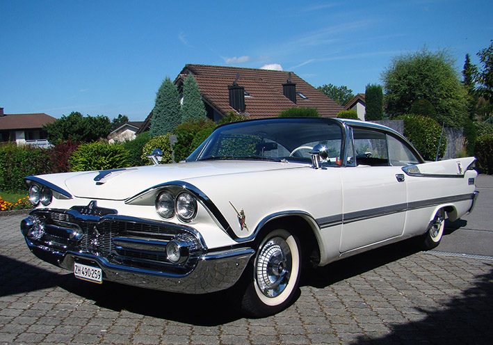 (01 Danis 1959 Dodge.jpg) (01 Danis 1959 Dodge.jpg)
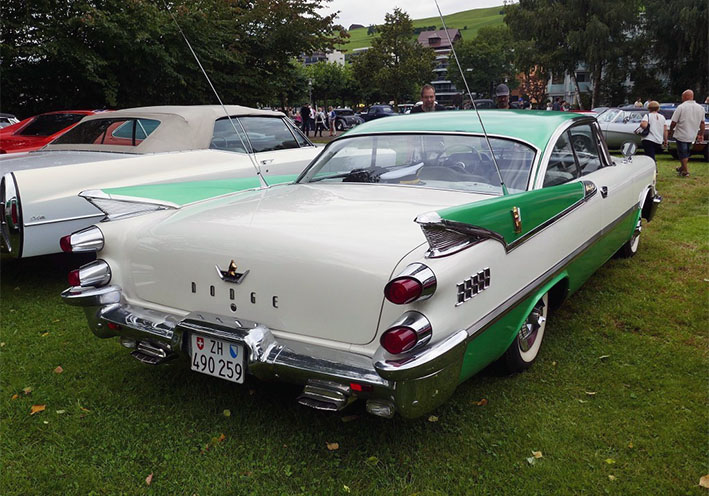 (02 Green Foiled.jpg) (02 Green Foiled.jpg)
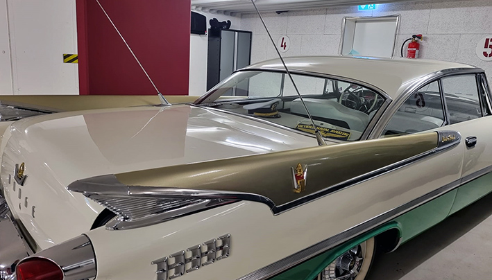 (03 Foiling green to golden.jpg) (03 Foiling green to golden.jpg)
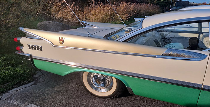 (03a Foiling green to golden.jpg) (03a Foiling green to golden.jpg)
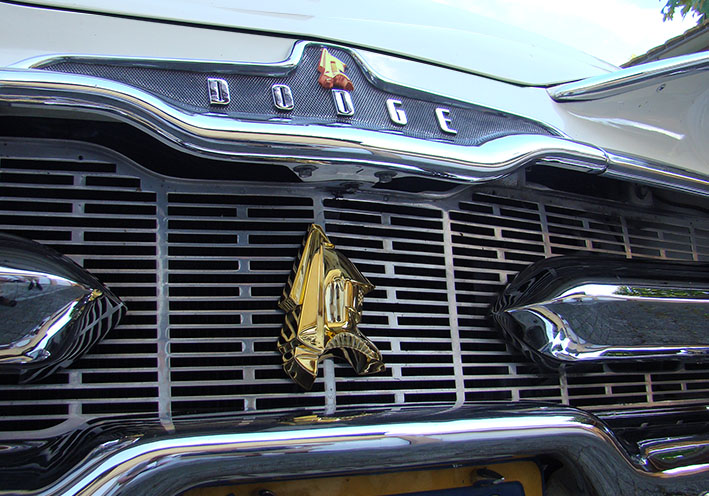 (04 Danis 1959 Dodge Front.jpg) (04 Danis 1959 Dodge Front.jpg)
Attachments
----------------
01 Danis 1959 Dodge.jpg (160KB - 151 downloads)
02 Green Foiled.jpg (132KB - 141 downloads)
03 Foiling green to golden.jpg (160KB - 146 downloads)
03a Foiling green to golden.jpg (121KB - 150 downloads)
04 Danis 1959 Dodge Front.jpg (147KB - 144 downloads)
|
|
| |
|
Expert
Posts: 1215
Location: SWITZERLAND | sermey - 2022-11-07 2:28 PM Foiling a 1959 Dodge: . . . . this 1959 Dodge is on the best way to become a noble vehicle - nice to look at. And now all done, within 24 hours - what a prospect!! Who shows next Golden 1959 Dodge? - SERGE -
Edited by sermey 2022-11-09 12:06 PM
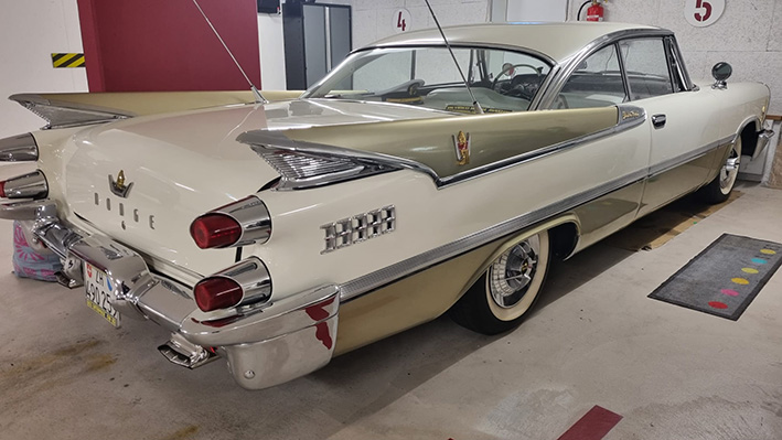 (Danis Golden 1959 Dodge.jpg) (Danis Golden 1959 Dodge.jpg)
Attachments
----------------
Danis Golden 1959 Dodge.jpg (119KB - 148 downloads)
|
|
| |
|

Expert
Posts: 3579
Location: Blythewood, SC | Do you mean a vinyl wrap? |
|
| |
|
Expert
Posts: 1215
Location: SWITZERLAND | 57plymouth - 2022-11-09 6:15 PM Do you mean a vinyl wrap? Yes Brian. A Vinyl especial for cars, as applied on many Sport Cars. It is tricky to mount, on curves to avoid scroll must heat somewhat with a Hair-Dryer. Needs some practical skill, artistic vein and the motivation to go forward. - SERGE - |
|
| |
|
Regular
Posts: 78
Location: Okielahoma | I'm a little surprised you haven't tried to run 59 Cadillac tail light lenses, maybe you thought about it, seems to be in the same vein as some of your cosmetic ideas. |
|
| |
|
Elite Veteran
Posts: 682
Location: Finland | I had to read this thread from the beginning again...made me humble...
Which gas springs did you end up with Serge(trunk lid springs)?
And which stroke? |
|
| |
|
Expert
Posts: 1215
Location: SWITZERLAND | 22mafeja - 2023-03-12 9:43 AM I had to read this thread from the beginning again...made me humble... Which gas springs did you end up with Serge(trunk lid springs)? Gas Spring Length 275 mm Hub 100 mm Force 200 N with Ball Head Ball Joint, Black. Style Name:275|100|200N|Black This Gas Spring, Ralf, comes in addition to the existing Torsion Spring Bars in the trunk. Check for correct position, then drill and mount. By removing the clips it can easily be removed and replaced. Good Luck - SERGE - .
Edited by sermey 2023-03-12 7:26 AM
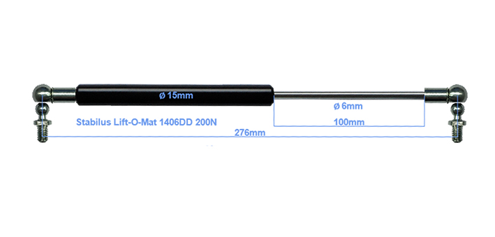 (Gas Spring for Trunk.jpg) (Gas Spring for Trunk.jpg)
Attachments
----------------
Gas Spring for Trunk.jpg (65KB - 130 downloads)
|
|
| |
|
Elite Veteran
Posts: 682
Location: Finland | Thanks Serge. |
|
| |
|
Location: The Mile High City | Amazing! The flat fold-down looks wonderful
Edited by Lancer Mike 2023-03-12 12:56 PM
|
|
| |
|
Expert
Posts: 1215
Location: SWITZERLAND | Covering the bottom fold: Most bottom folds under the sill plate look messed up, any more when they are rusty. For protection and a nicer appearance it can be coated as I did with a special black adhesive Tape 3M-33 (01). Of course, the other side of the fold must be sealed when coated, as I did with noise reduction panels on all interior surfaces, and as described earlier. As the surfaces showed very uneven (02), I started another way by grinding the metal peaks (03), and looked for an adequate Silicone Rubber Profile (04). This, filled with black special adhesive sealant, then set on (05). The excess of glue was immediately removed, the car left for a week to dry through (06). Now, the fold is protected, especially view from side it looks straight and neatly, as it should be all the time (07). Another “Make-Up” on my 1959 Dodge Custom Royal Convertible. - SERGE -
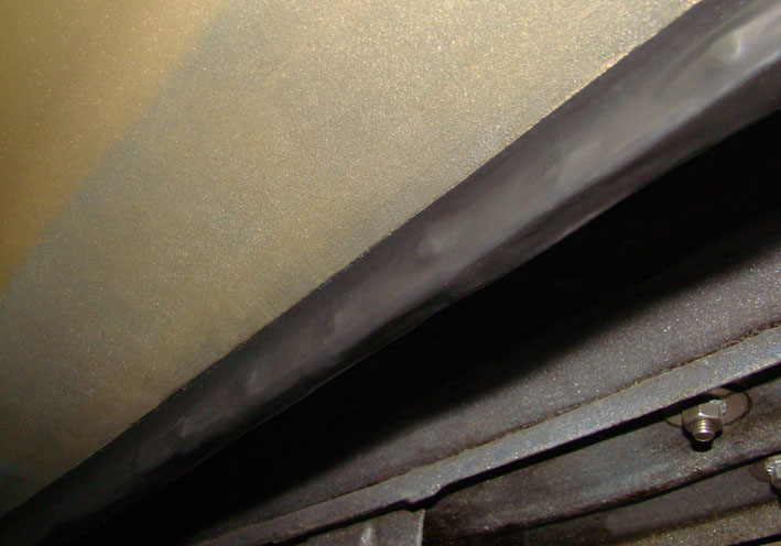 (01 Fold coated with Scotch Tape.jpg) (01 Fold coated with Scotch Tape.jpg)
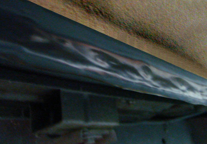 (02 Uneven Surfaces.jpg) (02 Uneven Surfaces.jpg)
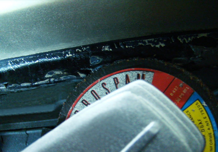 (03 Grinding the Peaks.jpg) (03 Grinding the Peaks.jpg)
 (04 Silicone Rubber Profile.jpg) (04 Silicone Rubber Profile.jpg)
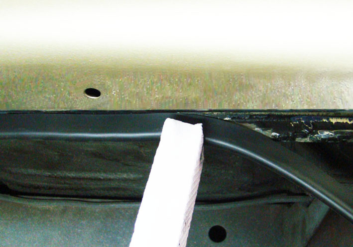 (05 Pre-Setting the Profile.jpg) (05 Pre-Setting the Profile.jpg)
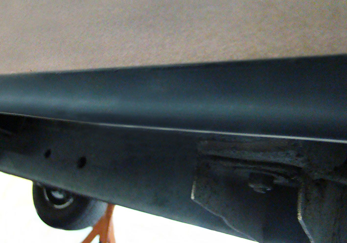 (06 Preview.jpg) (06 Preview.jpg)
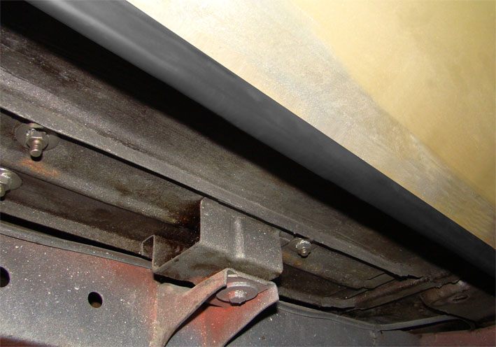 (07 Profile Optimized and Fixed.jpg) (07 Profile Optimized and Fixed.jpg)
Attachments
----------------
01 Fold coated with Scotch Tape.jpg (80KB - 123 downloads)
02 Uneven Surfaces.jpg (74KB - 118 downloads)
03 Grinding the Peaks.jpg (91KB - 121 downloads)
04 Silicone Rubber Profile.jpg (72KB - 124 downloads)
05 Pre-Setting the Profile.jpg (84KB - 124 downloads)
06 Preview.jpg (104KB - 124 downloads)
07 Profile Optimized and Fixed.jpg (93KB - 131 downloads)
|
|
| |
|
Exner Expert 10K+
Posts: 10042
Location: Lower Mainland BC | .
Very neat and clean there Serge. Good job.
I hate (strongly dislike) the equivalent pinch weld on my 56 Dodge. So far I have cleaned and painted it (but still light blue) but I was thinking of painting it flat black to make it visually disappear from the side.
But now I see yours with the rubber covering and I say "Hmm...that looks good", I am re-thinking the black paint thing.
Where did you get the rubber profile, i.e. what was its original purpose? (Where would I look over here in Canada?)
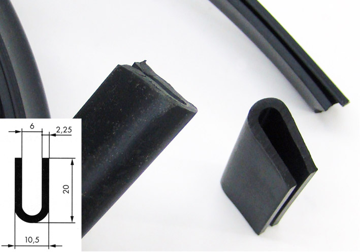
My pinch weld flange (pretty straight but still ugly)
Edited by 56D500boy 2023-03-26 3:09 PM
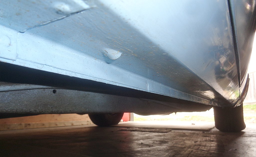 (DaveFs56DodgeRockerPanelPinchWeldFlange_Mar26_2023.jpg) (DaveFs56DodgeRockerPanelPinchWeldFlange_Mar26_2023.jpg)
Attachments
----------------
DaveFs56DodgeRockerPanelPinchWeldFlange_Mar26_2023.jpg (147KB - 122 downloads)
|
|
| |
|
Expert
Posts: 1215
Location: SWITZERLAND | I never doubt Dave, that you have a pronounced sense for aesthetics, recognizing the optical effect . . . . . There are various suppliers for such profiles. For your car another profile would fit better, check first the thickness of the fold. - SERGE - https://shop.maagtechnic.ch/de/elastomertechnik-gummiprofile/u-profile-pr1579278053429099/?searchTerm=gummi+u-profile just for dimensions, look at page 3
Edited by sermey 2023-03-26 3:16 PM
|
|
| |
|
Exner Expert 10K+
Posts: 10042
Location: Lower Mainland BC | sermey - 2023-03-26 12:12 PM
just for dimensions, look at page 3
So I guessing that you used this one:
U-Profil rund EPDM 5,5x18mm U-Profil rund EPDM 5,5x18mm Maagtechnic Artikelnr: 10007460 Vorrätig
Vergleichen
??? |
|
| |
|
Expert
Posts: 1215
Location: SWITZERLAND | The used profile is not shown in the internet. Here a scan from the big catalogue, you will see Art. No. 122157. I think the narrow one Art. Nr. 122195 may better fit to your car. You will need total up to 5m. - SERGE -
Edited by sermey 2023-03-27 5:40 AM
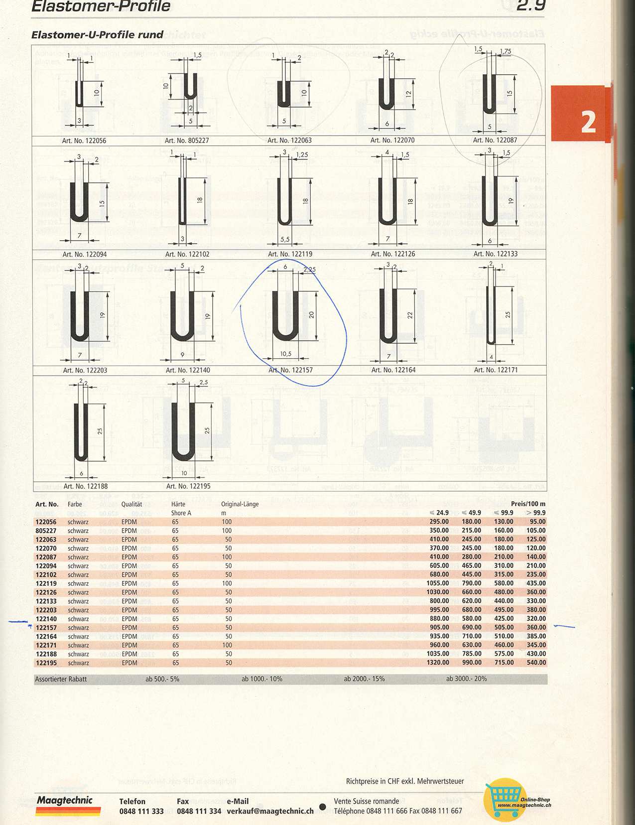 (U-Profile 150.jpg) (U-Profile 150.jpg)
Attachments
----------------
U-Profile 150.jpg (196KB - 125 downloads)
U-Profile 150.pdf (200KB - 129 downloads)
|
|
| |
|
Expert
Posts: 1215
Location: SWITZERLAND | Checking the Fuel Pump: As shown earlier, in my car I have two fuel pumps, one original mechanic and a second electrical, switchable. After about 30 sec activation of the electrical Fuel Pump, the glass fuel filter (01) becomes full, can even hear the lower speed of the pump. Now the car will start up immediately. This the main advantage. The two pumps work in parallel. Due to the non-return valves in the out port of the units, only the stronger one contributes fuel to the carburators. My fuel line offers the option to connect a pression gauge (02). The fuel pressure of the single mechanical pump, at idle 450 rpm, is shown in (03), at 2000 rpm in (04). The fuel pressure of the single electrical pump is shown in (05, and is independent of the rpm. When both pumps are active, the dominant electrical pump defines the fuel pressure. So far, just for information. – SERGE –
Edited by sermey 2023-04-01 9:49 AM
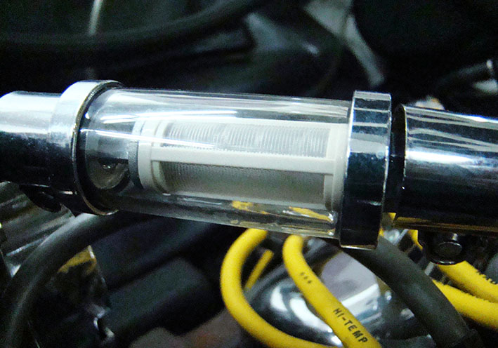 (01 Glass Fuel Filter.jpg) (01 Glass Fuel Filter.jpg)
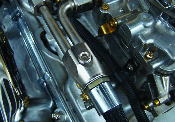 (02 Port for Pressure Gauge.jpg) (02 Port for Pressure Gauge.jpg)
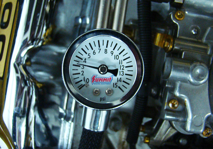 (03 Mechanical Fuel Pump 450rpm.jpg) (03 Mechanical Fuel Pump 450rpm.jpg)
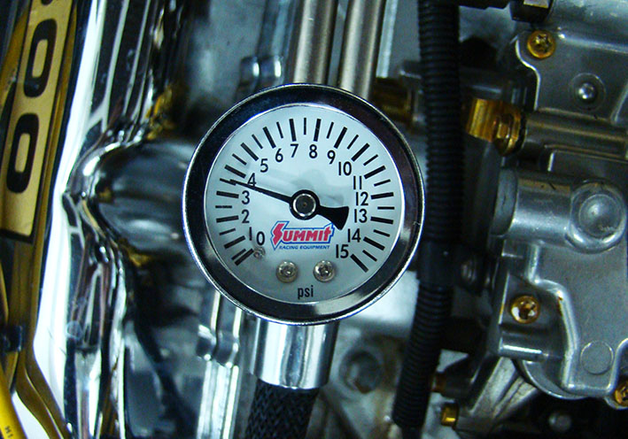 (04 Mechanical Fuel Pump 2000rpm.jpg) (04 Mechanical Fuel Pump 2000rpm.jpg)
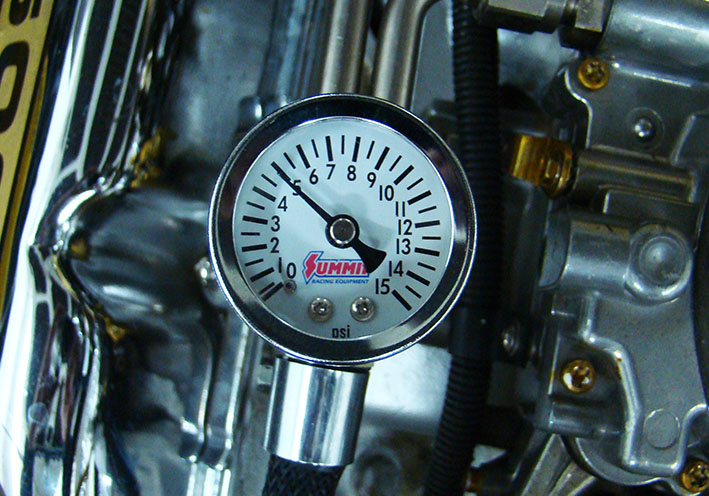 (05 Electrical Fuel Pump.jpg) (05 Electrical Fuel Pump.jpg)
Attachments
----------------
01 Glass Fuel Filter.jpg (107KB - 122 downloads)
02 Port for Pressure Gauge.jpg (136KB - 117 downloads)
03 Mechanical Fuel Pump 450rpm.jpg (127KB - 118 downloads)
04 Mechanical Fuel Pump 2000rpm.jpg (135KB - 122 downloads)
05 Electrical Fuel Pump.jpg (133KB - 115 downloads)
|
|
| |
|
Expert
Posts: 1215
Location: SWITZERLAND | Dual Front Door Catch System: Hitting the door to another car or wall – a big disaster due to the expensive replacement of the rare sheet metal. This Dual Front Door Catch System, passenger and driver side, for 1959 Dodge and Plymouth (10), may fit as well for years 1956 (11), 1957 and 1958. HighTech 3D engineered and simulated. Precision stainless steel parts, Laser cut to fit to minimum gap of 1mm. Smooth, floating roller-based operation, thus no additional door friction until snap (01). Dual trap position. First trap (02) aperture 65cm (03). Second trap (04) aperture 110cm (05). Fully opened (06) 150cm as original. Determined snap-in (07). Release force adjustable. A unique compact set: 32 items, included stainless hex screws with matching tool, drilling template (08) and the mounting instructions. After drilled ready for mount. An indispensable safety feature, for a valuable vehicle, avoiding damage when parking, and on slanting streets. A standard on all today’s vehicles. - SERGE -
Edited by sermey 2023-04-22 5:48 AM
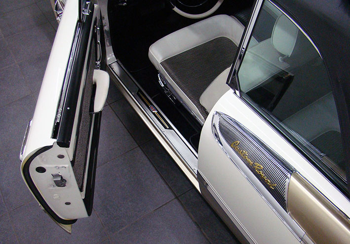 (01 Top View.jpg) (01 Top View.jpg)
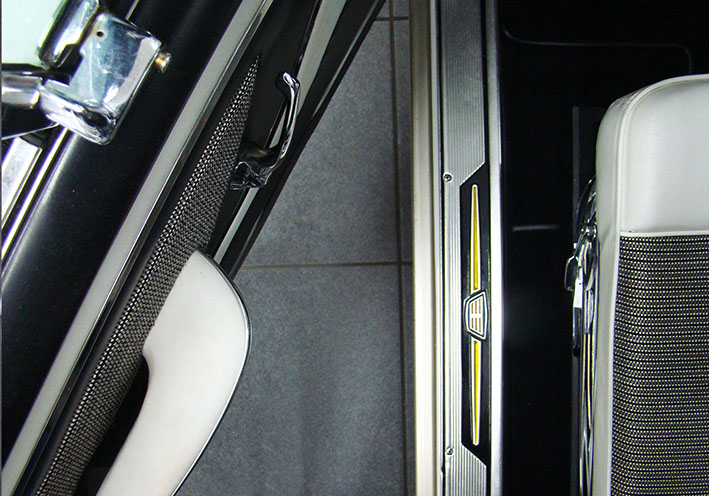 (02 First Trap.jpg) (02 First Trap.jpg)
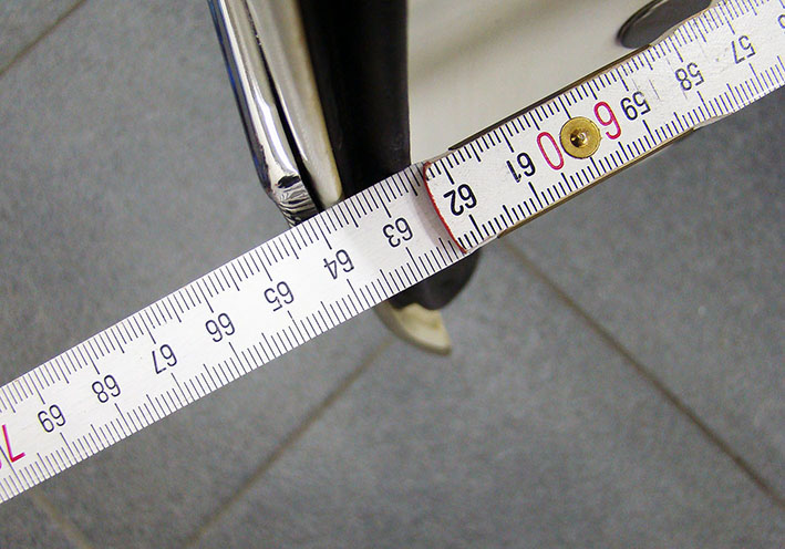 (03 Measured 64cm.jpg) (03 Measured 64cm.jpg)
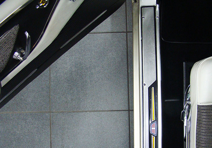 (04 Second Trap.jpg) (04 Second Trap.jpg)
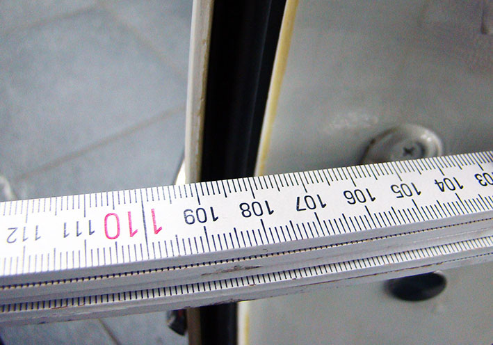 (05 Measured 110cm.jpg) (05 Measured 110cm.jpg)
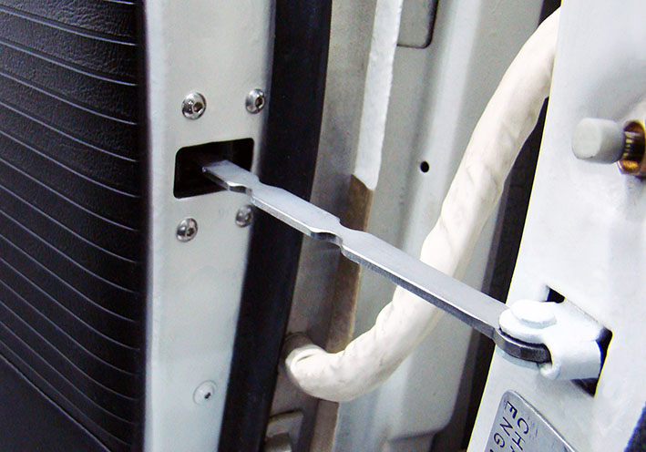 (06 Door fully opened 150cm.jpg) (06 Door fully opened 150cm.jpg)
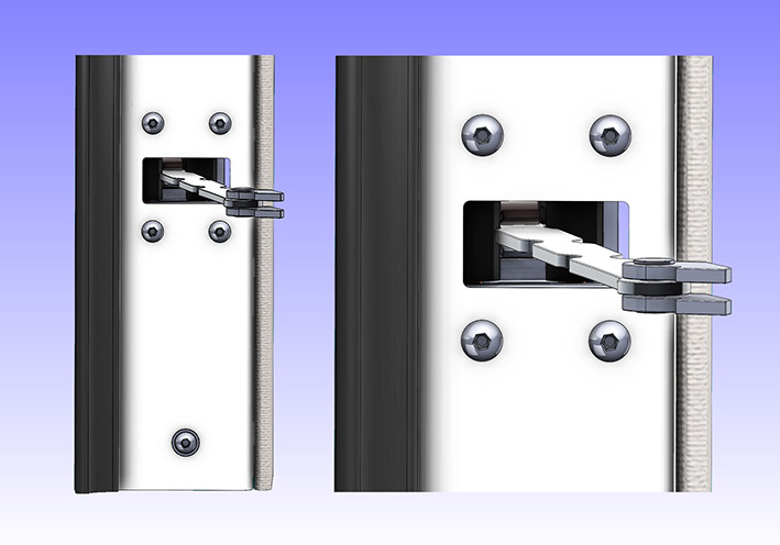 (07 Front View CAD.jpg) (07 Front View CAD.jpg)
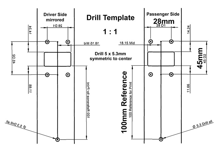 (08 Drilling Template A4.jpg) (08 Drilling Template A4.jpg)
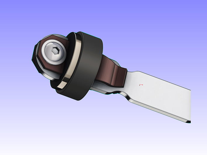 (09 Assembled Trap Bar CAD.jpg) (09 Assembled Trap Bar CAD.jpg)
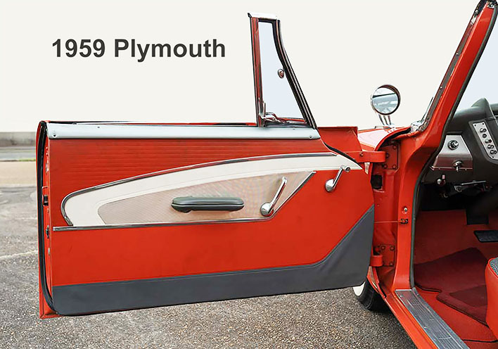 (10 1959 Plymouth Door Fully Opened.jpg) (10 1959 Plymouth Door Fully Opened.jpg)
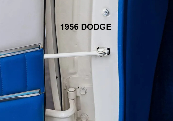 (11 56DodgeD500_4502_RightsideCourtesyLightPlunger.jpg) (11 56DodgeD500_4502_RightsideCourtesyLightPlunger.jpg)
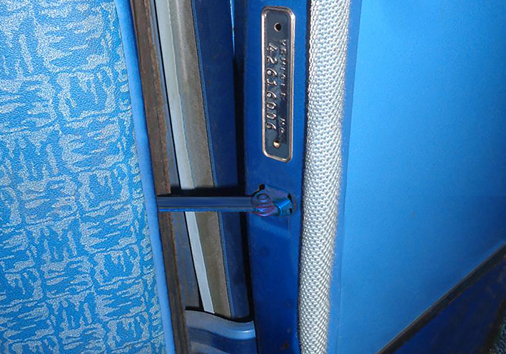 (12 56Dodge Dave FrontDoorShowingDoorStopInAction.jpg) (12 56Dodge Dave FrontDoorShowingDoorStopInAction.jpg)
Attachments
----------------
01 Top View.jpg (128KB - 110 downloads)
02 First Trap.jpg (133KB - 110 downloads)
03 Measured 64cm.jpg (112KB - 124 downloads)
04 Second Trap.jpg (122KB - 130 downloads)
05 Measured 110cm.jpg (110KB - 108 downloads)
06 Door fully opened 150cm.jpg (102KB - 114 downloads)
07 Front View CAD.jpg (68KB - 109 downloads)
08 Drilling Template A4.jpg (90KB - 111 downloads)
09 Assembled Trap Bar CAD.jpg (75KB - 128 downloads)
10 1959 Plymouth Door Fully Opened.jpg (118KB - 111 downloads)
11 56DodgeD500_4502_RightsideCourtesyLightPlunger.jpg (114KB - 122 downloads)
12 56Dodge Dave FrontDoorShowingDoorStopInAction.jpg (159KB - 108 downloads)
|
|
| |
|
Expert
Posts: 1215
Location: SWITZERLAND | Compatibilty to other Mopars: I was asked about. Here to compare, a picture with transparent front at fully opened door, and the link: http://www.forwardlook.net/forums/forums/thread-view.asp?tid=34070&start=115
Edited by sermey 2023-04-23 2:33 PM
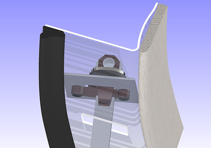 (2023-04-23 Original Front Door Stop FWL.jpg) (2023-04-23 Original Front Door Stop FWL.jpg)
Attachments
----------------
2023-04-23 Original Front Door Stop FWL.jpg (89KB - 101 downloads)
|
|
| |
|
Expert
Posts: 1215
Location: SWITZERLAND | Checking the Neutral Safety Switch: (01) It happens once, the starter motor didn’t engage in N position. I switched the push buttons to R, then to D, and back again to N. So the starter ran and then motor as well. To know: This device is not a switch from a classic point of view. It consists of a movable bolt as contact element, guided by the isolation, and pressed out by an internal spring. It activates the relay to the starter. Unmounted: Whatever the position of this contact, the resistance between the wire connection and the bolt (04) should always show 0 Ohm, as well when bolt point is pressed down (02). Measured 0.1 Ohm on point, 0.00 Ohm when fully pushed in (for test). As stated, this device is not a switch, but acts as a flexible conductor, or simply a contact device. Thus, following I will talk about contact, or about safety switch. The contact is ON when the transmission lever (03) touches the point of the safety switch, and thus the connection turns grounded. This only happens when the gear is set to N position (04). For safety, the starter motor should only work in N position. So far so good and well known. - I did some electrical measurements on this device. from wire connection to ground (04), the safety switch always mounted, and the cable connected. Measuring Ohms the battery is disconnected: Result should be: (Instrument checked for 0.0 Ohm at short circuit) Position ignition switch OFF and battery disconnected: (N) position -> 0 Ohm (R or D) position -> High Ohm Position ignition switch ON and battery connected: (N) position -> 0 Volt (R or D) position -> Battery Voltage 12V Result was: Position ignition switch OFF and battery disconnected: (N) position -> switched multiple: 1.7 – 6.9 Ohm (06), but never 0 as it should show. Sometimes even up to 60 Ohm (!). I unlocked the adjustment wheel (07) by rotating out to get the gearshift control cable somewhat movable. Now pushed it in < - > out to find minimum Ohm reading, fixed it at this optimized position. Result Now at optimized position: Position ignition switch OFF and battery disconnected: (N) position -> up to max 1.3 Ohm (08) Position ignition switch ON and battery connected: (N) position -> starter motor will always work This proceeding may be considered as another, simple operational check of the Neutral Safety Switch, without unmount. A way for electrically fine position the control cable to the peak of the contact lever (03). - SERGE - N.B If the safety switch shows in any position 0 Ohm, resp. 0 Volt, then there is a short-circuit, and no start protection. If there is always High Ohm, resp. 12 Volt, then there is no contact at all. The car cannot be started. May be too low pressure from the bolt to the contact lever, the internal spring may be weakened or even broken. In both cases the switch must be replaced (09). By switching the gear selector (10) before starting several times from R to N and the other way back, the contact may be cleaned. Some basics and pictures presented earlier by courtesy of Phil Courant (Phil_the_frenchie).
Edited by sermey 2023-04-29 12:16 PM
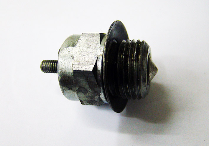 (01 Neutral Safety Switch.jpg) (01 Neutral Safety Switch.jpg)
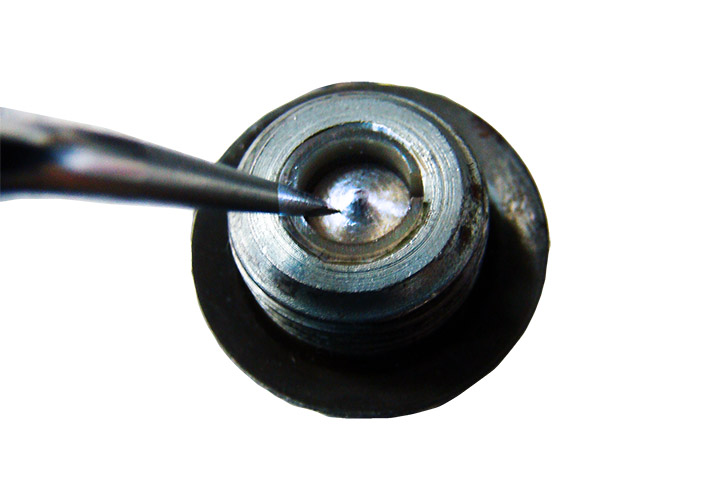 (02 Contact Pressed in.jpg) (02 Contact Pressed in.jpg)
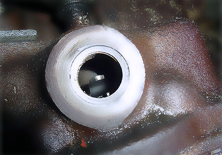 (03 View on Transmission Contact Lever.jpg) (03 View on Transmission Contact Lever.jpg)
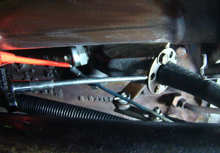 (04 Electric Test Connection.jpg) (04 Electric Test Connection.jpg)
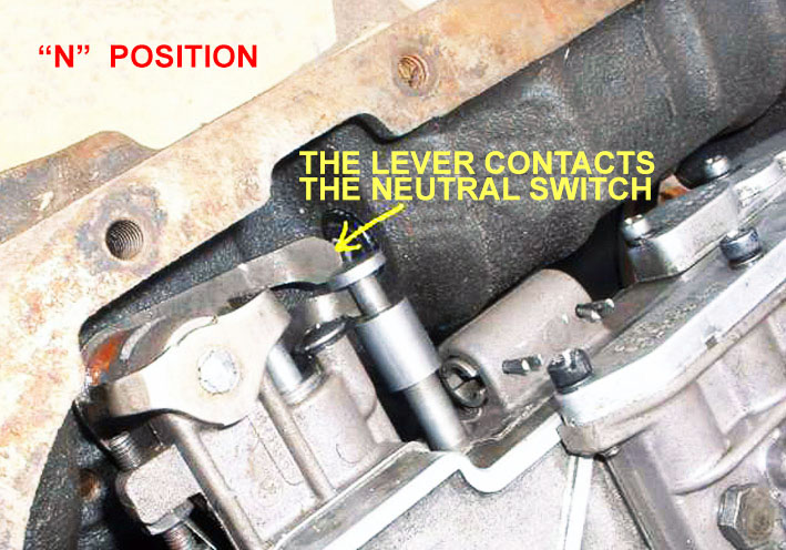 (05 PhilCourantsSafetyLeverContactingSafetySwitchInNeutral.jpg) (05 PhilCourantsSafetyLeverContactingSafetySwitchInNeutral.jpg)
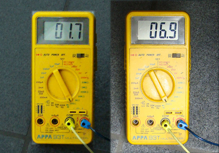 (06 Reading 1.7 - 6.9 Ohm.jpg) (06 Reading 1.7 - 6.9 Ohm.jpg)
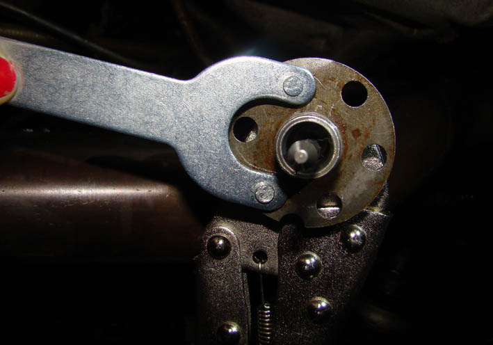 (07 Turning out the adjustment washer.jpg) (07 Turning out the adjustment washer.jpg)
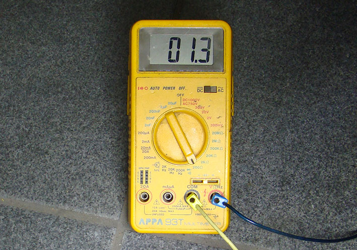 (08 Reading max Ohm 1.3 Ohm.jpg) (08 Reading max Ohm 1.3 Ohm.jpg)
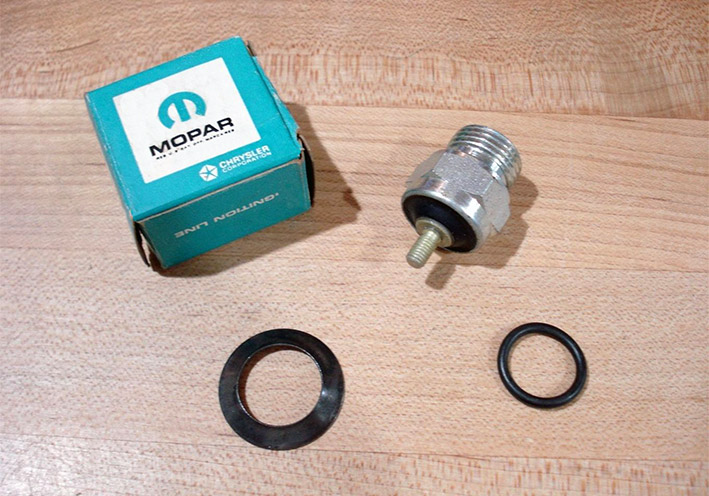 (09 PhilCourantsNeutralSafetySwitch_1704283.jpg) (09 PhilCourantsNeutralSafetySwitch_1704283.jpg)
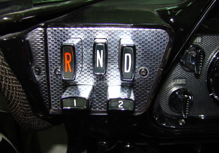 (10 Push Button Unit.jpg) (10 Push Button Unit.jpg)
Attachments
----------------
01 Neutral Safety Switch.jpg (81KB - 117 downloads)
02 Contact Pressed in.jpg (62KB - 102 downloads)
03 View on Transmission Contact Lever.jpg (154KB - 111 downloads)
04 Electric Test Connection.jpg (111KB - 107 downloads)
05 PhilCourantsSafetyLeverContactingSafetySwitchInNeutral.jpg (129KB - 101 downloads)
06 Reading 1.7 - 6.9 Ohm.jpg (123KB - 111 downloads)
07 Turning out the adjustment washer.jpg (69KB - 126 downloads)
08 Reading max Ohm 1.3 Ohm.jpg (136KB - 112 downloads)
09 PhilCourantsNeutralSafetySwitch_1704283.jpg (138KB - 102 downloads)
10 Push Button Unit.jpg (115KB - 106 downloads)
|
|
| |
|
Expert
Posts: 1215
Location: SWITZERLAND | Color of a Convertible Top: There are two ways for select the color of a convertible top: Original color or Custom color. When I got my 1959 Dodge Custom Royal Lancer Convertible, it had a white top, greyed-out similar as shown in (01), and partly broken at the edges. The new included white top I gave to a friend as gift, for I decided to switch to black. Can say, never a white top on a white car, for the color will barely match, fade out in time, and show any dirt. Except to a white paint, a white top will fit to any other color. On the other side, any other top color may fit to a white car. This my personal view from an esthetical and practical point. The black top on my convertible looks always as new, now even many years later (02)(03)(04). - SERGE -
Edited by sermey 2023-05-29 2:51 AM
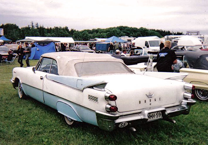 (01 Convertible Top White Greyed.jpg) (01 Convertible Top White Greyed.jpg)
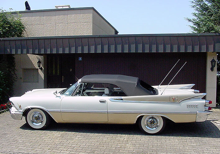 (02 Convertible Top Black.jpg) (02 Convertible Top Black.jpg)
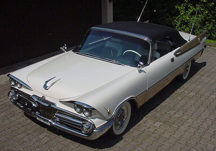 (03 Convertible Top Black.jpg) (03 Convertible Top Black.jpg)
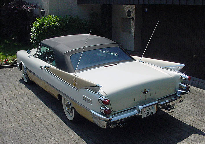 (04 Convertible Top Black.jpg) (04 Convertible Top Black.jpg)
Attachments
----------------
01 Convertible Top White Greyed.jpg (110KB - 96 downloads)
02 Convertible Top Black.jpg (142KB - 100 downloads)
03 Convertible Top Black.jpg (141KB - 104 downloads)
04 Convertible Top Black.jpg (105KB - 108 downloads)
|
|
| |
|
Expert
Posts: 1215
Location: SWITZERLAND | Swivel Seat Back Snap System: The back of my swivel seats never kept in back position. When braking strongly, without passenger sitting, the seat turned to front. I was told that there is a retarder spring in the hinge, and found it in the 59 Dodge Parts List as 23-45-55 Swivel Seat Back Retarder (00). Ahead years a FWL-friend sent me pictures with the exact dimensions (01 – 05), and could model in 3D-CAD (06). It had just to be reproduced from a bent spring steel profile . . . but I never did. Attached the 3D CAD-File (07). Now I restarted to solve this problem and came to a simple snap system, even Master Exner would have liked. As learned by experience, most Mopar people is not in the position to pay for expensive precision laser-cut spring brackets, as it should be needed. Hence I will friendly show here next, how to do-it-yourself, from scratch. You will start without knowing how it works, illustrated by 3D-CAD in RealView, step by step. - SERGE -
Edited by sermey 2023-06-08 3:54 PM
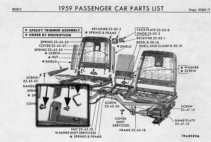 (00 1959 Dodge Parts List Spring 23-45-55 .jpg) (00 1959 Dodge Parts List Spring 23-45-55 .jpg)
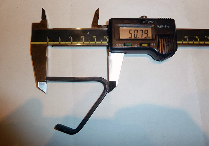 (01 Dimensions Swivel Seat Back Retarder Spring.jpg) (01 Dimensions Swivel Seat Back Retarder Spring.jpg)
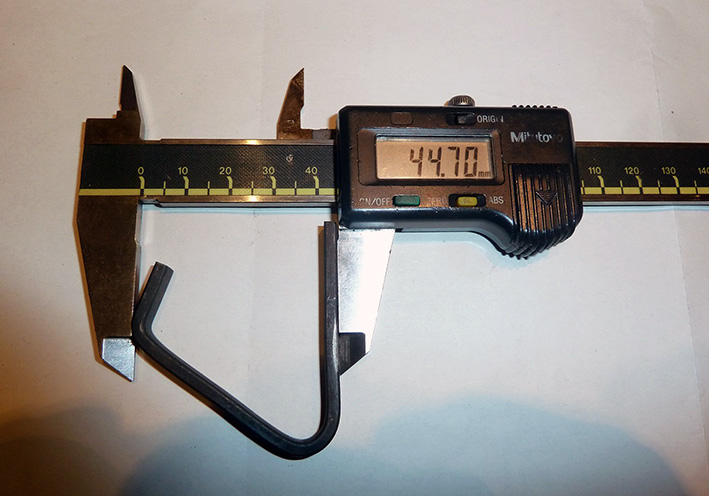 (02 Dimensions Swivel Seat Back Retarder Spring.jpg) (02 Dimensions Swivel Seat Back Retarder Spring.jpg)
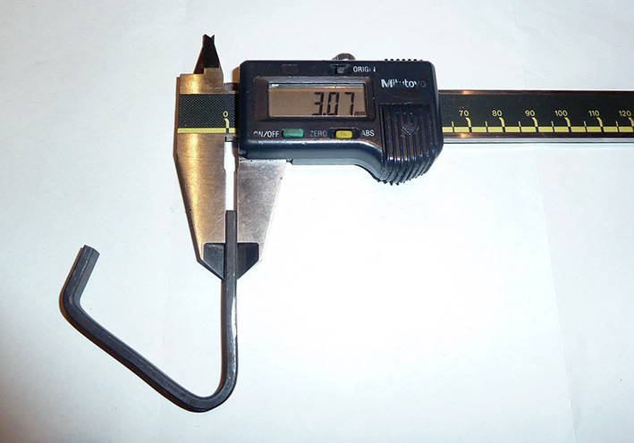 (03 Dimensions Swivel Seat Back Retarder Spring.jpg) (03 Dimensions Swivel Seat Back Retarder Spring.jpg)
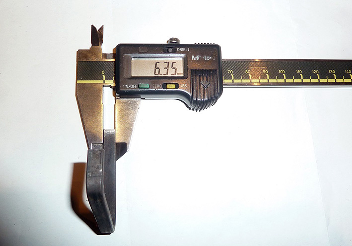 (04 Dimensions Swivel Seat Back Retarder Spring.jpg) (04 Dimensions Swivel Seat Back Retarder Spring.jpg)
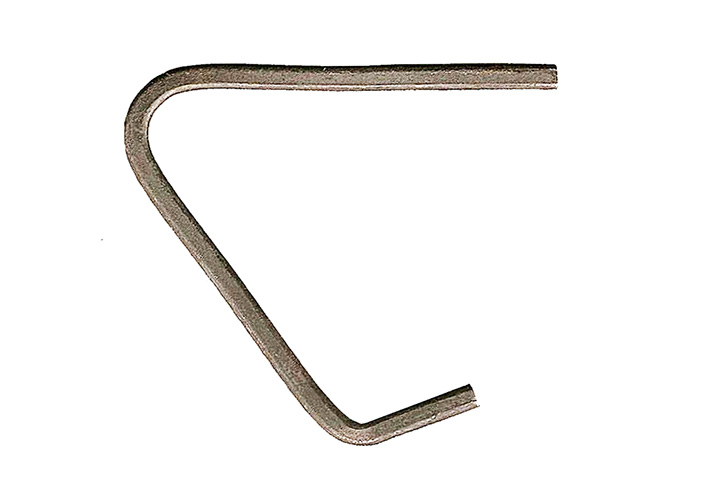 (05 Swivel Seat Back Retarder Spring.jpg) (05 Swivel Seat Back Retarder Spring.jpg)
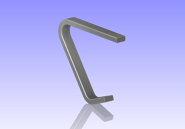 (06 CAD Swivel Seat Back Retarder Spring.jpg) (06 CAD Swivel Seat Back Retarder Spring.jpg)
Attachments
----------------
00 1959 Dodge Parts List Spring 23-45-55 .jpg (181KB - 92 downloads)
01 Dimensions Swivel Seat Back Retarder Spring.jpg (116KB - 97 downloads)
02 Dimensions Swivel Seat Back Retarder Spring.jpg (118KB - 97 downloads)
03 Dimensions Swivel Seat Back Retarder Spring.jpg (99KB - 103 downloads)
04 Dimensions Swivel Seat Back Retarder Spring.jpg (92KB - 99 downloads)
05 Swivel Seat Back Retarder Spring.jpg (50KB - 102 downloads)
06 CAD Swivel Seat Back Retarder Spring.jpg (68KB - 100 downloads)
07 CAD Swivel Seat Back Retarder Spring.STEP (73KB - 104 downloads)
|
|
| |
|
Elite Veteran
Posts: 1168
Location: D-70199 Heslach | Off topic,- Sermey, are you going to lakeside-meet on the coming weekend? |
|
| |
|
Expert
Posts: 1215
Location: SWITZERLAND | |
|
| |
|
Elite Veteran
Posts: 1168
Location: D-70199 Heslach | sermey - 2023-06-14 4:28 PM
I think so, on sunny Sunday. Hope to meet you there, Tom.
Look for a 69 Barracuda w/ Mod Top |
|
| |
|
Expert
Posts: 1215
Location: SWITZERLAND | |
|
| |
|
Expert
Posts: 1215
Location: SWITZERLAND | sermey - 2023-06-08 7:19 PM Retarder Spring Swivel Seatback (Correction): I just noticed that the retarder spring is placed on the wrong side. Forced from down-up it will initially move and touch the left side (09). Correct? “errare humanum est” - SERGE -  Edited by sermey 2023-06-28 3:51 AM
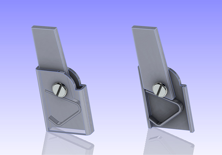 (09 CAD Retarder Spring corrected Position.jpg) (09 CAD Retarder Spring corrected Position.jpg)Attachments ---------------- 09 CAD Retarder Spring corrected Position.jpg (104KB - 101 downloads) |
|
| |
|
Expert
Posts: 1215
Location: SWITZERLAND | Swivel Seat Back Snap System (1): Now you will see how to do yourself the snap system, illustrated by CAD, step by step. For better distinguish, shown as well in line view. The seatback is represented by its arm end, right side hinge. The left side proceed similar. All illustrations are mostly self-explanatory. In the last part I will show the real application on my car. Proceeding Part 1 1. Take a stainless spring steel sheet metal, preferably type 1.4310 C1300, thickness 0.5 – 1 mm. Cut it to length 110 x 12mm, and bend it around the O-Profile (01), so as to fit around the cross-section: Di 16.4mm, Ri 5mm. I call it the spring bracket. For easier access the seatback can be removed. 2. The spring bracket is pushed over the O-Profile, aligned to the upper border, and fixed by a clamp. The seatback is mounted, kept in fully Rear Position (Pos. 1, grey), 0 deg: Now pre-drill 3mm, perpendicular over the screw axis, in the center and 6mm from border of the spring bracket. To get all straight in-line, drill through all-in-one step (02). The spring steel require a hard driller. Then the mounted spring (fix it!) can be used as a template for the O-profile (03). When done remove the spring bracket. From now, the pre-drilled O-profile 3.0mm, will be used as drilling template (04). 3. Set the seatback in fully Rear position, pre-drill again 3mm through the seatback arm (Position 1). Same in Front Position (Pos. 3, green), 65deg (05). And again in Center Position (Pos. 2, blue), 32.5deg (06). Or may choose your preferred intermediate position. For multiple snap positions, multiple holes can be drilled. Will always drill only through the seatback arm. On removed seatback, drill-up all from 3mm to 6.0mm, and add on both sides a chamfer 1.0mm-45deg, or d = 8.0mm using a countersink (07). These holes will define the 3 snap positions (08). 4. The spring bracket removed, drill-up from 3mm to 6.0mm, cut and round the end as shown (09). Now the spring bracket, the key component of the system, is done and ready(10). It should exactly fit when fully pushed-in on the O-profile. STEP-files are attached for the bent (11) and the flat (12) spring bracket. Now you may already find out how this system works. – SERGE –
Edited by sermey 2023-07-08 5:35 AM
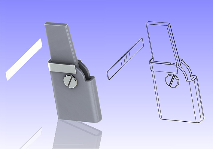 (01 Create Stainless Spring Bar 100 x 12 x 0.5mm and bend.jpg) (01 Create Stainless Spring Bar 100 x 12 x 0.5mm and bend.jpg)
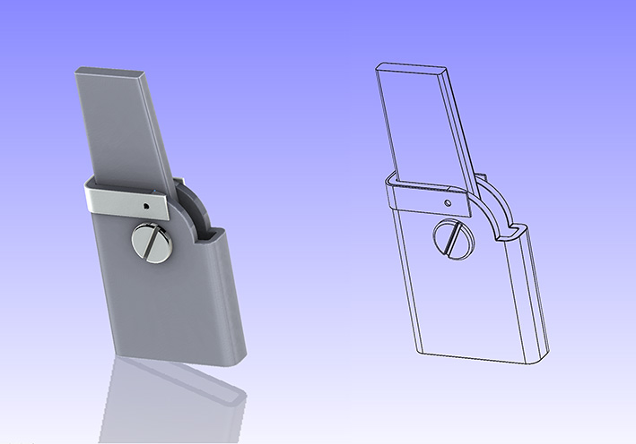 (02 Seatback in Rear Position - predrill 3mm.jpg) (02 Seatback in Rear Position - predrill 3mm.jpg)
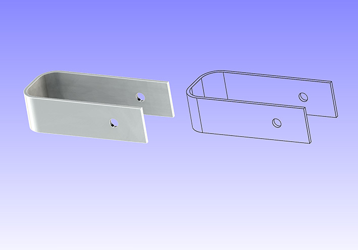 (03 Spring Bracket - bent and pre-drilled 3mm.jpg) (03 Spring Bracket - bent and pre-drilled 3mm.jpg)
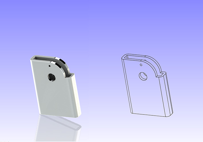 (04 O-Profile as template pre-drilled 3mm.jpg) (04 O-Profile as template pre-drilled 3mm.jpg)
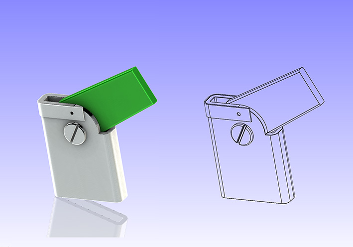 (05 Seatback in Front Position - PreDrill again 3mm.jpg) (05 Seatback in Front Position - PreDrill again 3mm.jpg)
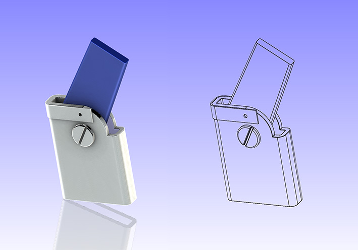 (06 Seatback in Center Position - PreDrill again 3mm.jpg) (06 Seatback in Center Position - PreDrill again 3mm.jpg)
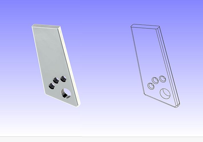 (07 3 Snap Holes drilled-up 3mm to 6mm .jpg) (07 3 Snap Holes drilled-up 3mm to 6mm .jpg)
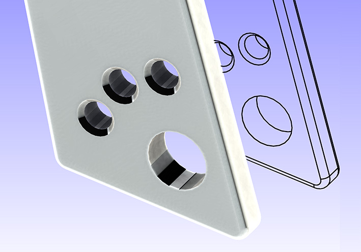 (08 Applied Chamfer 0.5mm 45deg to snap holes.jpg) (08 Applied Chamfer 0.5mm 45deg to snap holes.jpg)
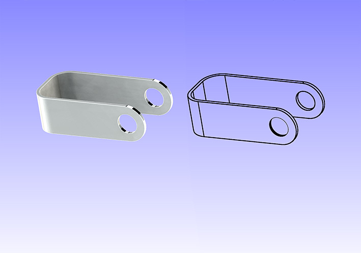 (09 Spring Bracket drilled-up to 6mm - End rounded.jpg) (09 Spring Bracket drilled-up to 6mm - End rounded.jpg)
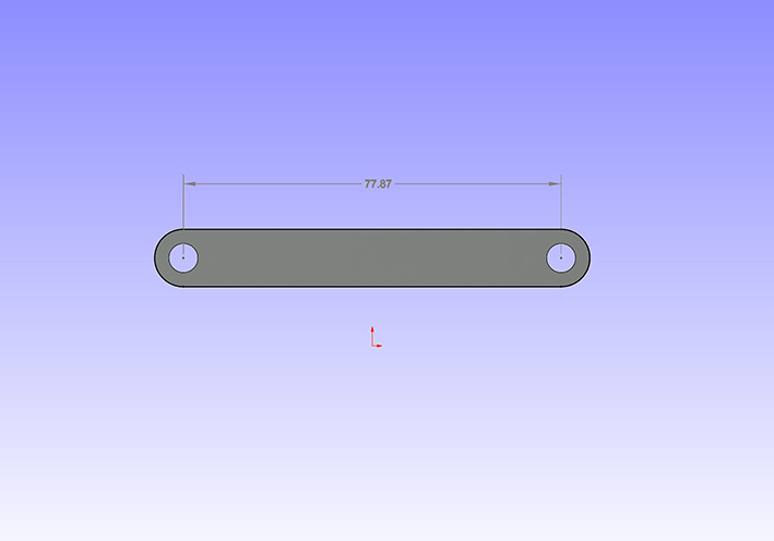 (10 Flat Bracket L = 101.87 W = 12mm d = 77.87mm D = 6.0mm.jpg) (10 Flat Bracket L = 101.87 W = 12mm d = 77.87mm D = 6.0mm.jpg)
Attachments
----------------
01 Create Stainless Spring Bar 100 x 12 x 0.5mm and bend.jpg (90KB - 93 downloads)
02 Seatback in Rear Position - predrill 3mm.jpg (79KB - 99 downloads)
03 Spring Bracket - bent and pre-drilled 3mm.jpg (70KB - 94 downloads)
04 O-Profile as template pre-drilled 3mm.jpg (72KB - 98 downloads)
05 Seatback in Front Position - PreDrill again 3mm.jpg (84KB - 89 downloads)
06 Seatback in Center Position - PreDrill again 3mm.jpg (83KB - 99 downloads)
07 3 Snap Holes drilled-up 3mm to 6mm .jpg (75KB - 102 downloads)
08 Applied Chamfer 0.5mm 45deg to snap holes.jpg (103KB - 96 downloads)
09 Spring Bracket drilled-up to 6mm - End rounded.jpg (75KB - 98 downloads)
10 Flat Bracket L = 101.87 W = 12mm d = 77.87mm D = 6.0mm.jpg (58KB - 94 downloads)
11 Spring Bracket.STEP (98KB - 135 downloads)
12 Spring Bracket Flat.STEP (40KB - 97 downloads)
|
|
| |
|
Expert
Posts: 1215
Location: SWITZERLAND | Swivel Seat Back Snap System (2): As the spring brackets are disposable, the o-profile (not the seat arm!) can be drilled up to 9.05mm, fitting the steel ball D = 9.0mm (13). The overall exploded view shows all needed parts and the function of the snap system (14). The two steel balls are inserted, then the spring bracket pushed over the o-profile to its final position (15), without the need of any tools and self positioning. The preloaded bracket is slightly bent in operation mode. In the cross section view the contact points can easy be verified (16)(17). Now the assembled snap system looks very discreet, the practical function must be approved, especially the snap force. This should be optimized, mostly with the diameter of the holes in the seat arm, and somewhat with a harder the spring bracket. In (3) I will present the applied realization on my 1959 Dodge Custom Royal Lancer Convertible.
After that a much simpler Seat Back Lock System, applicable for mostly all 2-Door Mopars 1957 - 1959 (?). - SERGE -
Edited by sermey 2023-08-06 7:13 AM
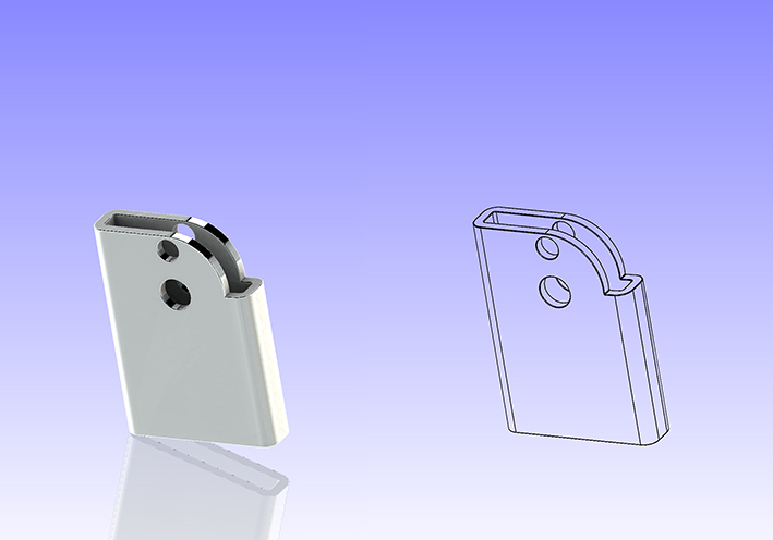 (13 Drill 9.05mm only through O-Profile.jpg) (13 Drill 9.05mm only through O-Profile.jpg)
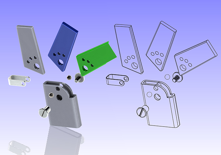 (14 Exploded View.jpg) (14 Exploded View.jpg)
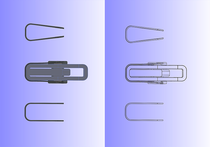 (15 Spring Brackets Flat - Active - Preloaded.jpg) (15 Spring Brackets Flat - Active - Preloaded.jpg)
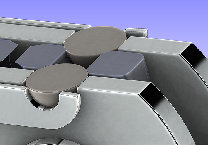 (16 Cross Section Zoomed Bracket Active 1.2mm.jpg) (16 Cross Section Zoomed Bracket Active 1.2mm.jpg)
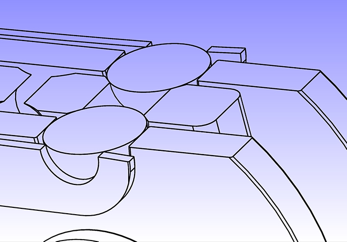 (17 Cross Section Zoomed Bracket Active 1.2mm.jpg) (17 Cross Section Zoomed Bracket Active 1.2mm.jpg)
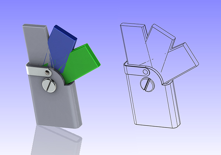 (18 Assembled Snap System 3 Positions.jpg) (18 Assembled Snap System 3 Positions.jpg)
Attachments
----------------
13 Drill 9.05mm only through O-Profile.jpg (100KB - 86 downloads)
14 Exploded View.jpg (148KB - 92 downloads)
15 Spring Brackets Flat - Active - Preloaded.jpg (109KB - 86 downloads)
16 Cross Section Zoomed Bracket Active 1.2mm.jpg (143KB - 98 downloads)
17 Cross Section Zoomed Bracket Active 1.2mm.jpg (158KB - 92 downloads)
18 Assembled Snap System 3 Positions.jpg (128KB - 91 downloads)
|
|
| |
|
Expert
Posts: 1215
Location: SWITZERLAND | Swivel Seat Back Snap System (3), Application: As intended for “Do-it-Yourself”, most operations are best described with pictures. This especially for “non-mechanical” readers. Apart from drilling, the main job needs the spring bracket. Organize some stainless spring sheet metal, d0.5 – 1.5mm (**) (01), and cut in stripes of 100 x 12mm (02). Bend, using the O-profile or another item as template (03). First tests (04). For easier process I found table clips in multipack, high flexible, 12mm x 0.6mm (05). Even very hard, could cut them with a scissor (06). Enlarge the existing radius to R5mm (07), and bend the other radius correspondingly (08) to fit the O-profile (09). Mark the drill position, just over the pivot (10), and drill D6mm on both sides (need HSS-CO Metal Drill and lubrication) (11). Shorten both ends with the metal scissor (12) to get the final length (13). After that, round them by machine grinding (14). The final spring bracket now can be pushed on for mark the drilling center (15). The seat back is set in the back – front- and mid position. Pre-drill first all with D3mm, trough all. Then remove the seat back, and drill up all holes in the arm from D3mm to D6mm (**), apply some chamfer (not shown). Still at removed back seat, drill up the O-profile to D9.05mm (16), as the steel balls have D9.00mm. Now, at mounted back seat, the steel balls can be loaded from both sides (17), then the spring bracket pushed over. It will keep in place when all is done accurately. The Swivel Back Seat Snap System is ready to operate (18). Result: I started first on the passenger side, rear and front position. The system as presented shows a too week snapping, as expected due to the thin spring d0.6mm, and too wide chamfer on the arm.. Means, for best snap the tagged values (**) need to be optimized. Conclusion: In view of a simpler and more useful Back Seat Lock solution, being presented soon, I don’t recommend to work on this snap system. Anyway, both work simultaneously, independent from each to other. For you this project shows the applied interaction between CAD and Mechanics. For me, it was another challenging game! - SERGE -
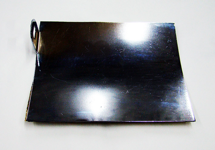 (01 Selected Stainless Sheet Metal.jpg) (01 Selected Stainless Sheet Metal.jpg)
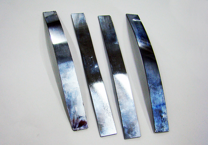 (02 Cut Metal Stripes.jpg) (02 Cut Metal Stripes.jpg)
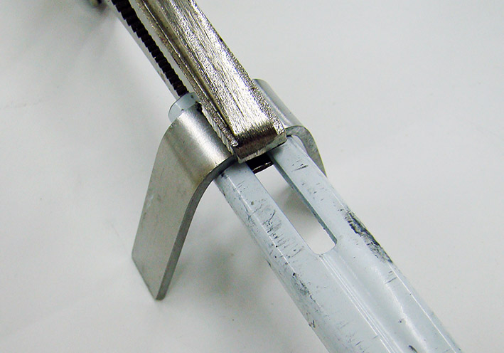 (03 Manual Bent with Profile as Template.JPG) (03 Manual Bent with Profile as Template.JPG)
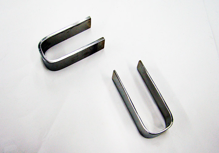 (04 First Tests.jpg) (04 First Tests.jpg)
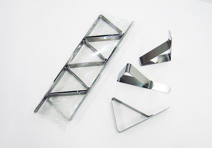 (05 Table Clips in Multipack.jpg) (05 Table Clips in Multipack.jpg)
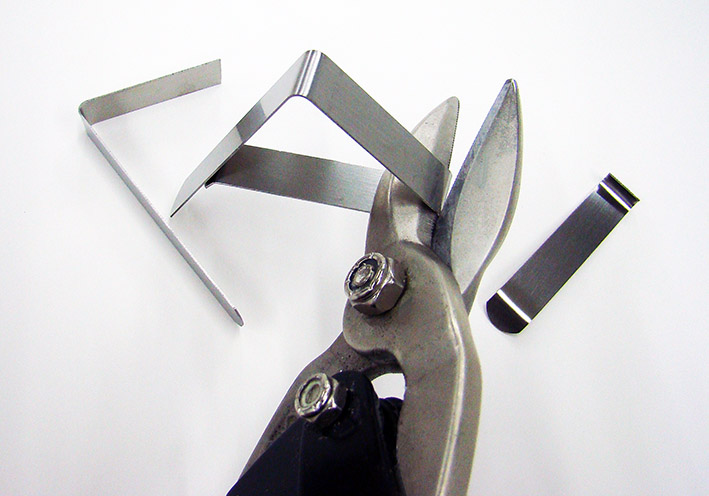 (06 Pre-Cut the Table Clips.jpg) (06 Pre-Cut the Table Clips.jpg)
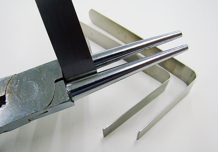 (07 Enlarge the Radius to 5mm.jpg) (07 Enlarge the Radius to 5mm.jpg)
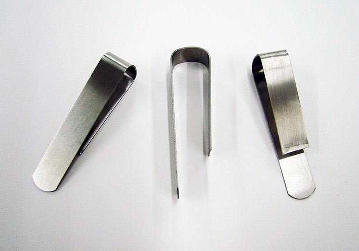 (08 Bent Stripes.jpg) (08 Bent Stripes.jpg)
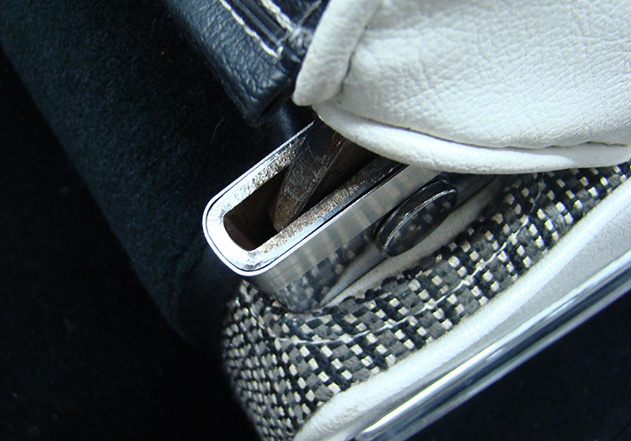 (09 Check the Roundings.jpg) (09 Check the Roundings.jpg)
 (10 Mark the Drill Position.jpg) (10 Mark the Drill Position.jpg)
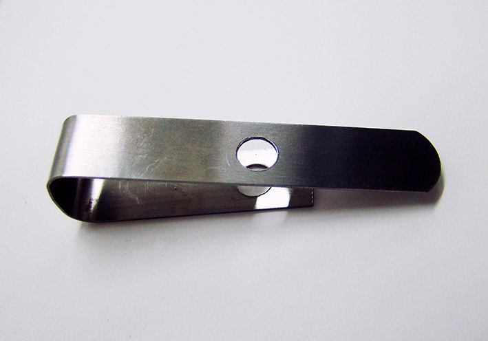 (11 Drilled 6mm.jpg) (11 Drilled 6mm.jpg)
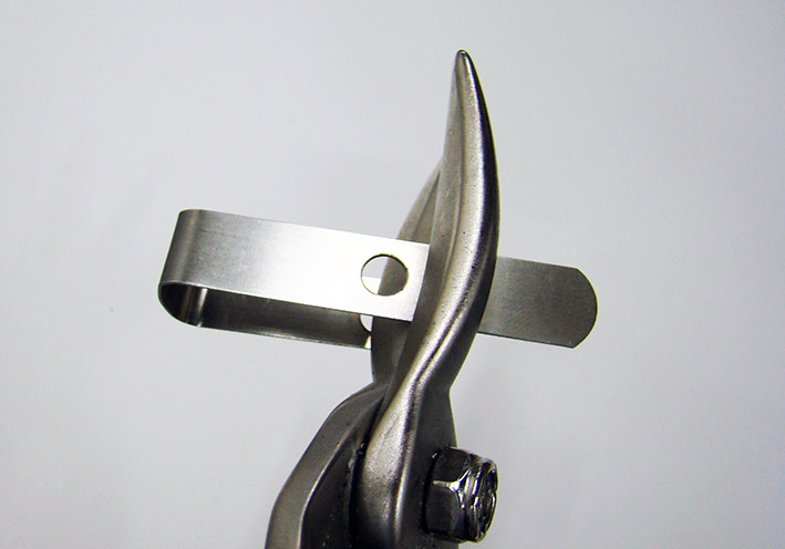 (12 Cut with Metal Scissor.jpg) (12 Cut with Metal Scissor.jpg)
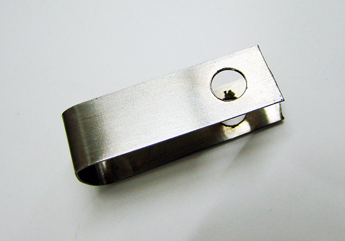 (13 Cut with Metal Scissor.jpg) (13 Cut with Metal Scissor.jpg)
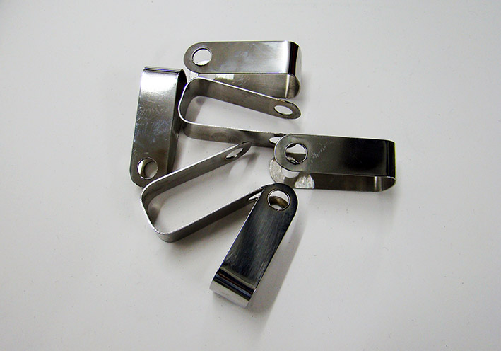 (14 Drilled Brackets rounded.jpg) (14 Drilled Brackets rounded.jpg)
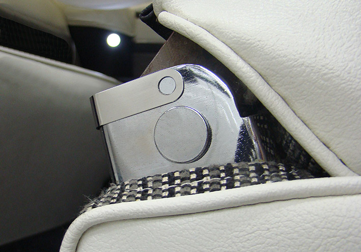 (15 Drilled Bracket mounted.jpg) (15 Drilled Bracket mounted.jpg)
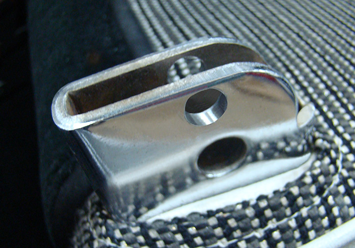 (16 O-Profile drilled up 9.05mm for Ball.jpg) (16 O-Profile drilled up 9.05mm for Ball.jpg)
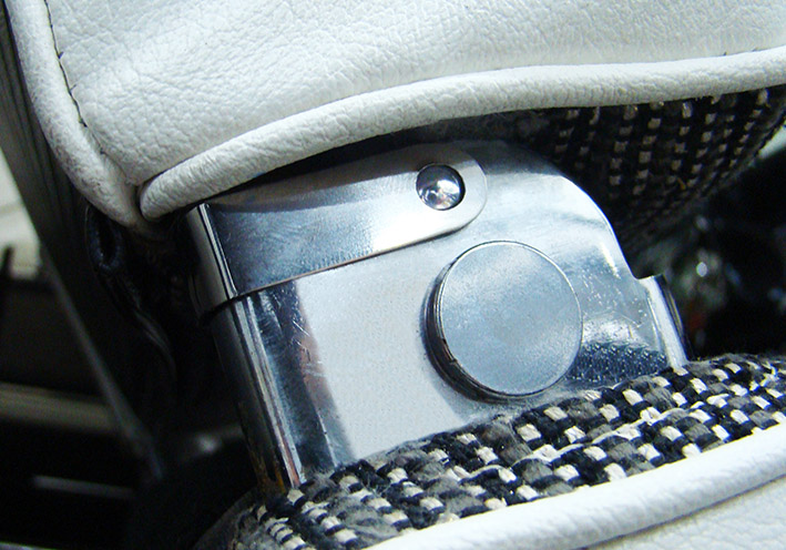 (17 Assembled Snap System.jpg) (17 Assembled Snap System.jpg)
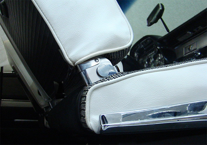 (18 Final System Overview.jpg) (18 Final System Overview.jpg)
Attachments
----------------
01 Selected Stainless Sheet Metal.jpg (118KB - 91 downloads)
02 Cut Metal Stripes.jpg (126KB - 99 downloads)
03 Manual Bent with Profile as Template.JPG (108KB - 81 downloads)
04 First Tests.jpg (93KB - 86 downloads)
05 Table Clips in Multipack.jpg (91KB - 86 downloads)
06 Pre-Cut the Table Clips.jpg (109KB - 104 downloads)
07 Enlarge the Radius to 5mm.jpg (127KB - 99 downloads)
08 Bent Stripes.jpg (107KB - 93 downloads)
09 Check the Roundings.jpg (149KB - 111 downloads)
10 Mark the Drill Position.jpg (123KB - 85 downloads)
11 Drilled 6mm.jpg (84KB - 88 downloads)
12 Cut with Metal Scissor.jpg (92KB - 95 downloads)
13 Cut with Metal Scissor.jpg (103KB - 95 downloads)
14 Drilled Brackets rounded.jpg (97KB - 99 downloads)
15 Drilled Bracket mounted.jpg (139KB - 92 downloads)
16 O-Profile drilled up 9.05mm for Ball.jpg (154KB - 82 downloads)
17 Assembled Snap System.jpg (165KB - 90 downloads)
18 Final System Overview.jpg (147KB - 102 downloads)
|
|
| |
|
Elite Veteran
Posts: 682
Location: Finland | Amazing stuff as always Serge. I think you are the FWL " quantum physician " |
|
| |
|
Expert
Posts: 1215
Location: SWITZERLAND | 22mafeja - 2023-08-13 8:20 AM Amazing stuff as always Serge. I think you are the FWL " quantum physician " What a compliment, Ralf. In respect to all here doing a big job on their Mopar, I try to compete somewhat on my own way. Thanks. - SERGE -
Edited by sermey 2023-08-14 1:53 AM
|
|
| |
|
Expert
Posts: 1215
Location: SWITZERLAND | Seat Back Lock: It was obvious to come across a lock solution -> ingenious as trivial. The few commercially available components prove it (01): 1. Flange head screw with inside hexagon, stainless steel, M5 x 30mm 2. Round Spacer Nut, stainless steel, M5 x 10 x 10mm 3. Conical Compression Spring, stainless steel, D12 x d6 x H12mm 4. Round Knob with threaded sleeve, glossy black, M5 x D21 x d12 x H21mm Components assembled $5 (02), set per vehicle $10 (03). The biggest effort is to find some vendors, then to the low cost adds the shipment, and for less than 20 pieces each you are mostly supplied. The round knob I cut from H21 to H15mm to appear more discreet (04). So let’s start, in less than 2 hours you get it: Drill D5mm through all, at fully rear seat back position, dimensions H17 - D13mm from border (05). It doesn’t influence the prior snap system (05a). Use a 90deg drill-adapter. Drill-up to D10mm from the other side, only the half O-profile and through the seat arm (06). It can as well be drilled at removed seat back. Then when re-assembled, do re-drill in one with a precision milling drill, so as both D10mm holes are exact in-line. To protect the upholstery apply a strong plastic sheet (07). The brittle HSS-Kobalt drill has broken, thus now shortened. Use reduced rpm and lubricate. For free moving the seat back, the arm needs a gap. Mark the center-line with a waterproof felt-pen. Held in the 5mm hole, and move the seat back front to rear (08). Offset the curved line to 6mm width, and cut-out using a jigsaw (09) (09a). Can see where rasped 4.5mm deep for increasing the seat back angle, as shown in: http://www.forwardlook.net/forums/forums/thread-view.asp?tid=23691&start=167 Now assemble all: Insert the screw with the spacer nut mounted. Put on the conical compression spring. The direction is indifferent. Turn-on the knob to a remaining play of 5.5mm, to be fixed with LOCTITE. The feature is ready to operate: - Push-in the knob for unlock (11): the seat back is free to move. - Move the seat back to front, till the lock unit snaps automatic in: It will stay locked at 60deg (10). - To unlock push-in again the knob (11): The seat back is free to turn back, to the rear position. It will snap in automatic and keep locked (12). There are many other M5 knobs available for make it more discreet, as balls in chrome 10mm, with flat head, or in miniature. I feel the presented version is handy, ergonomic and best for my car (13). Another exclusive feature for your Dodge (and other Mopars 1957 – 1959): Easy to build - simple to operate - comfortable for access to rear - steady at strong braking - strong and secure. A joy to do it and then use. Once more -> ingenious as trivial. - SERGE -
N.B. Next thread will show the corresponding CAD pictures only.
Edited by sermey 2023-08-16 11:18 PM
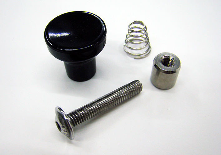 (01 Components.JPG) (01 Components.JPG)
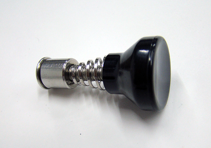 (02 Components Assembled.jpg) (02 Components Assembled.jpg)
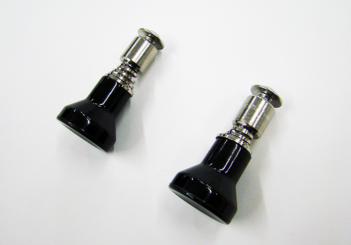 (03 Set per Vehicle.jpg) (03 Set per Vehicle.jpg)
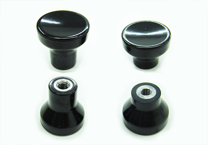 (04 Shortened Knob.jpg) (04 Shortened Knob.jpg)
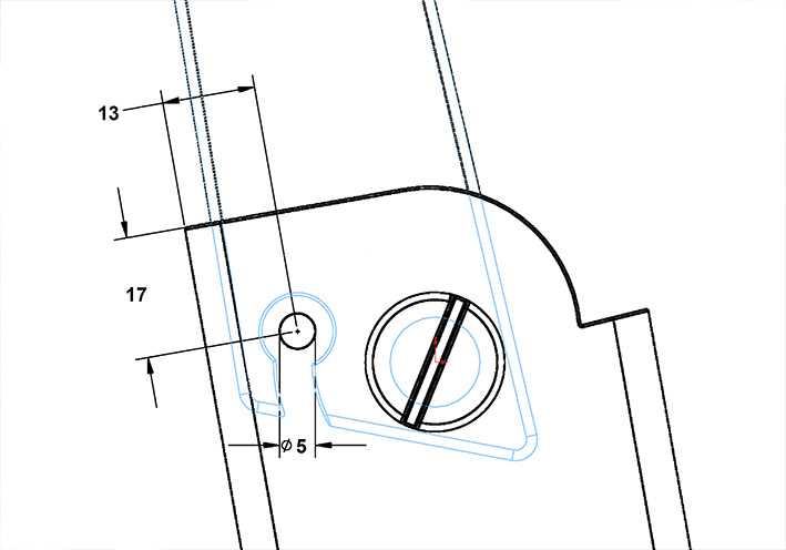 (05 Dimensions H13-V17mm.jpg) (05 Dimensions H13-V17mm.jpg)
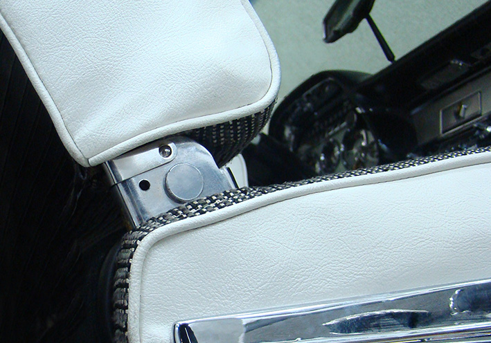 (05a Drill 5mm through all.jpg) (05a Drill 5mm through all.jpg)
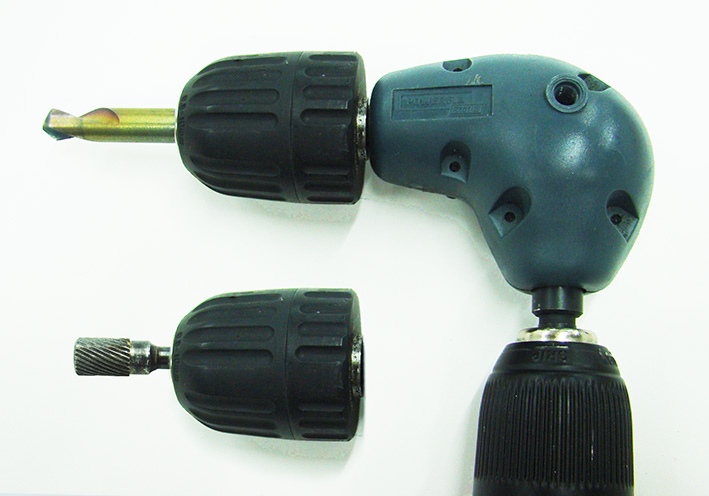 (06 Drill Adapter 90deg for 10mm.jpg) (06 Drill Adapter 90deg for 10mm.jpg)
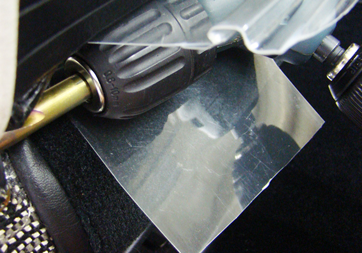 (07 Protected Upholstery.jpg) (07 Protected Upholstery.jpg)
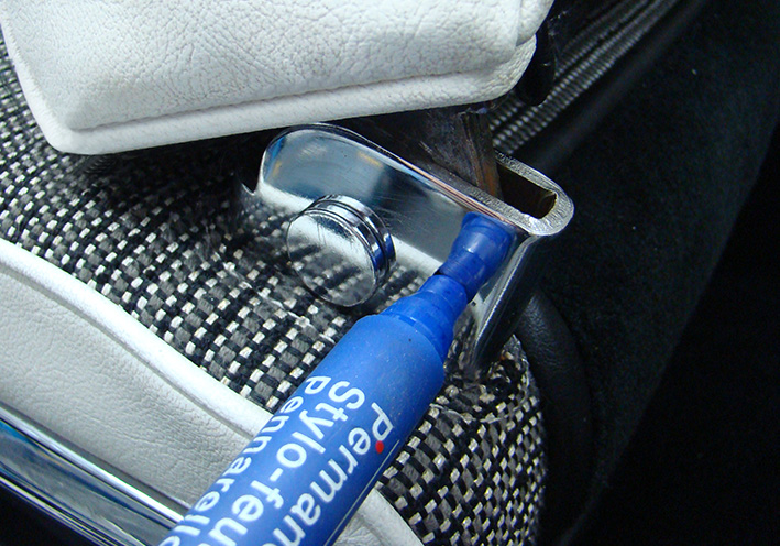 (08 Mark Center Gap.jpg) (08 Mark Center Gap.jpg)
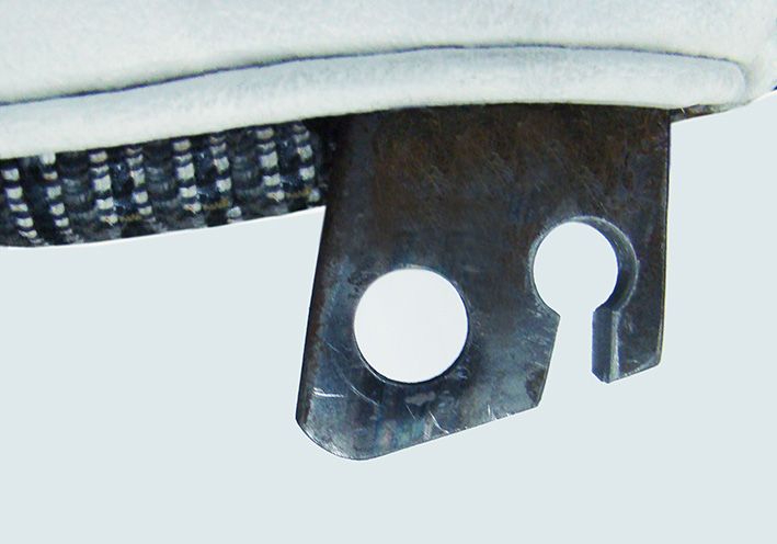 (09 Cut Gap.jpg) (09 Cut Gap.jpg)
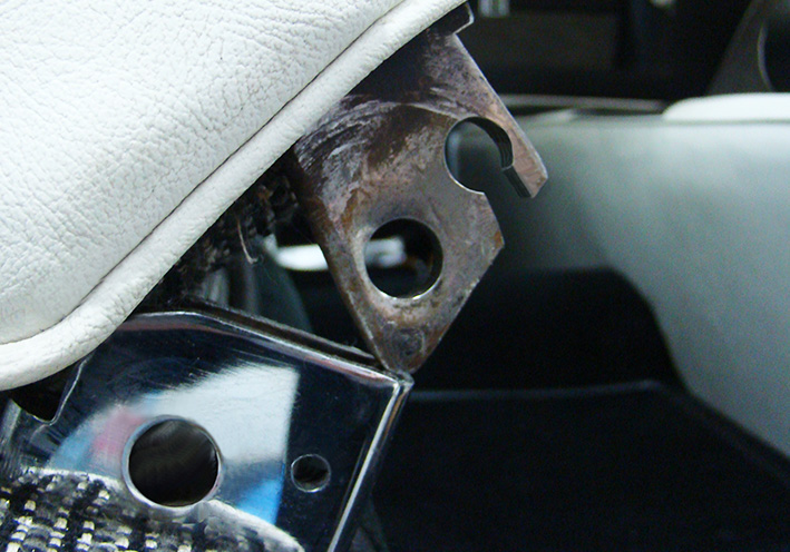 (09a Other Gap 6mm.jpg) (09a Other Gap 6mm.jpg)
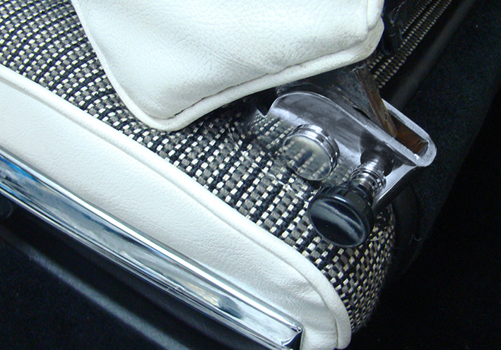 (10 Front Position Locked.jpg) (10 Front Position Locked.jpg)
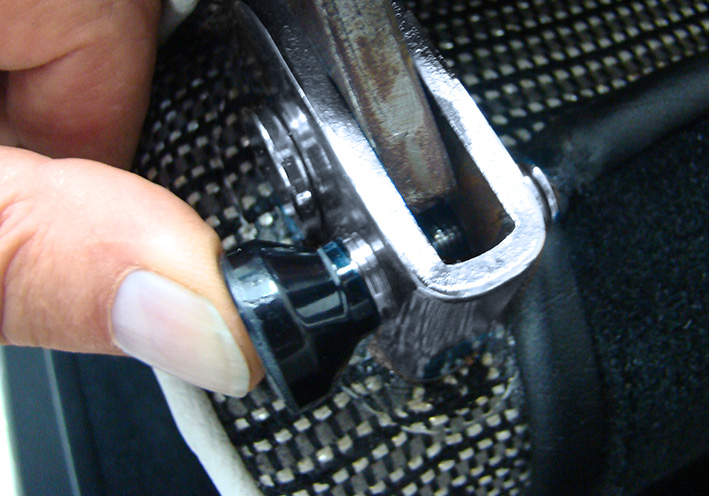 (11 Push-in for Unlock.jpg) (11 Push-in for Unlock.jpg)
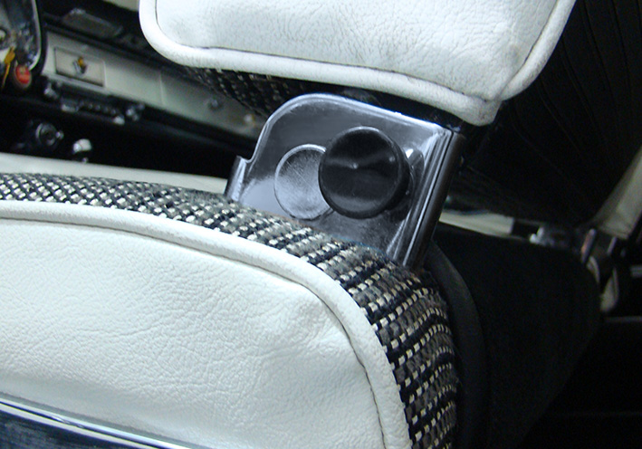 (12 Rear Position Locked.jpg) (12 Rear Position Locked.jpg)
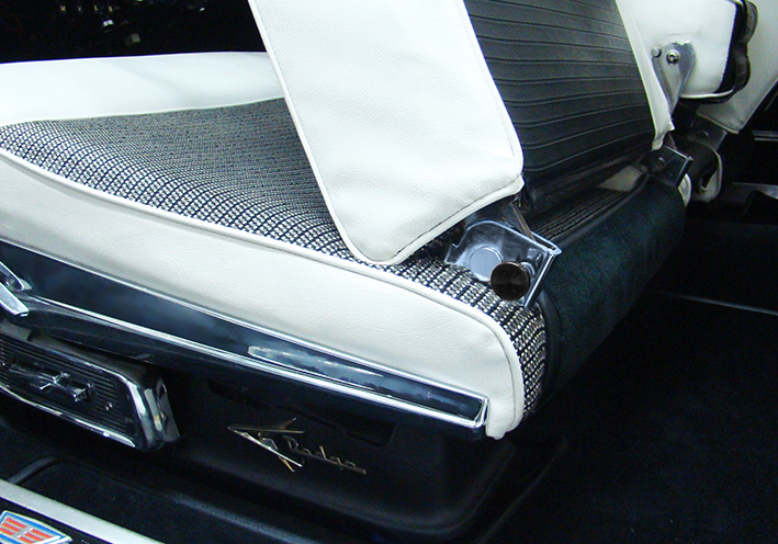 (13 Front Position Locked.jpg) (13 Front Position Locked.jpg)
Attachments
----------------
01 Components.JPG (125KB - 101 downloads)
02 Components Assembled.jpg (116KB - 86 downloads)
03 Set per Vehicle.jpg (104KB - 83 downloads)
04 Shortened Knob.jpg (95KB - 89 downloads)
05 Dimensions H13-V17mm.jpg (88KB - 83 downloads)
05a Drill 5mm through all.jpg (188KB - 93 downloads)
06 Drill Adapter 90deg for 10mm.jpg (116KB - 83 downloads)
07 Protected Upholstery.jpg (192KB - 94 downloads)
08 Mark Center Gap.jpg (218KB - 108 downloads)
09 Cut Gap.jpg (114KB - 93 downloads)
09a Other Gap 6mm.jpg (177KB - 95 downloads)
10 Front Position Locked.jpg (207KB - 136 downloads)
11 Push-in for Unlock.jpg (182KB - 83 downloads)
12 Rear Position Locked.jpg (175KB - 91 downloads)
13 Front Position Locked.jpg (197KB - 101 downloads)
|
|
| |
|
Board Moderator & Exner Expert 10K+
Posts: 13062
Location: Southern Sweden - Sturkö island | Very nice solution Serge, that will solve the seatback problems!
|
|
| |
|
Expert
Posts: 1215
Location: SWITZERLAND | |
|
| |
|
Expert
Posts: 1215
Location: SWITZERLAND | sermey - 2023-08-22 2:57 PM sermey - 2023-08-16 7:13 PM Seat Back LockIn Addition: Another variation
For those who like it less visible and even cheaper, the black knob can be replaced by another screw (16). Important that the flange distance is kept to 23mm (17).
Screw1: M5 x 5mm Screw 2: M5 x 18mm Now the unit can only be pushed-in, this for unlock the seat back. In the snap position the spring will shift it back and lock again. The seat back should be “unloaded” and in the snap-in position (18). – SERGE - 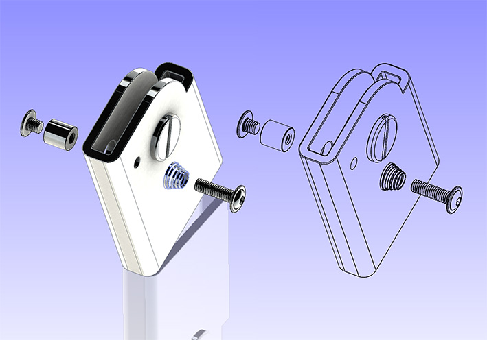 (16 No Black Knob CAD.jpg) (16 No Black Knob CAD.jpg)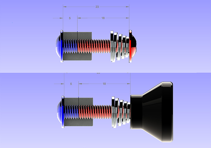 (17 Dimensions - Comparison CAD.jpg) (17 Dimensions - Comparison CAD.jpg)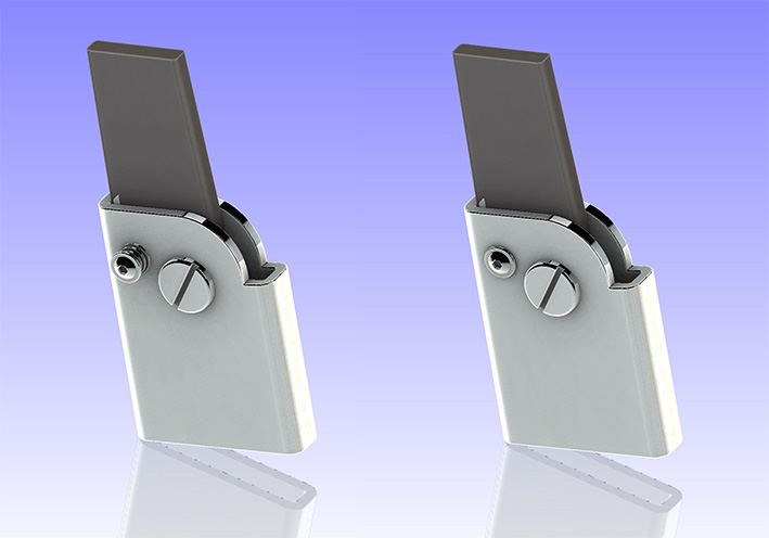 (18 Final View CAD.jpg) (18 Final View CAD.jpg)Attachments ---------------- 16 No Black Knob CAD.jpg (102KB - 90 downloads) 17 Dimensions - Comparison CAD.jpg (90KB - 82 downloads) 18 Final View CAD.jpg (76KB - 73 downloads) |
|
| |
|
Expert
Posts: 1215
Location: SWITZERLAND | Must precise: All previous swivel seat back considerations shown here are related to a 1959 Dodge Convertible.
Edited by sermey 2023-08-27 4:55 PM
|
|
| |
|
Expert
Posts: 1215
Location: SWITZERLAND | Conical Compression Spring: I was kindly asked to publish the supplier of the conical compression springs. Here it is (01) (02): https://www.amazon.de/-/en/dp/B09MRHZYK4?psc=1&ref=ppx_yo2ov_dt_b_product_details Then I added the 3D-CAD Models as PDF-Files for those interested in 3D Technology. The normal spring unloaded (04), the OP spring loaded (05) and the flat spring (06).Other file formats are too big to post here. When opened with Adobe Acrobat, accept to trust in Options (Message: 3D content has been disabled. Enable this feature if you trust this document). The models can be 3D handled (rotated, zoomed). Good luck when assembling. - SERGE -
Edited by sermey 2023-09-01 8:58 PM
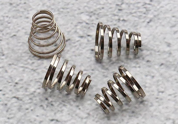 (01 Normal Skewer Spring.jpg) (01 Normal Skewer Spring.jpg)
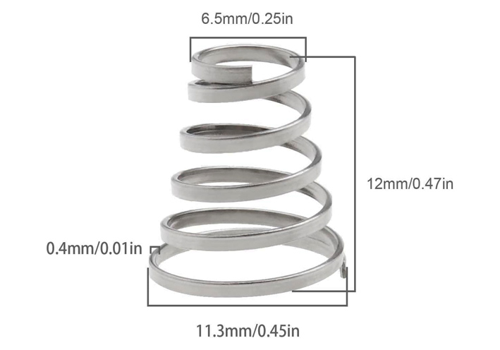 (02 Dimensions Skewer Spring.jpg) (02 Dimensions Skewer Spring.jpg)
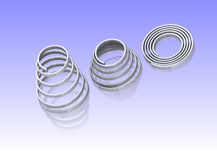 (03 Normal - OP - Flat Spring CAD.jpg) (03 Normal - OP - Flat Spring CAD.jpg)
Attachments
----------------
01 Normal Skewer Spring.jpg (129KB - 91 downloads)
02 Dimensions Skewer Spring.jpg (58KB - 85 downloads)
03 Normal - OP - Flat Spring CAD.jpg (94KB - 88 downloads)
04 Normal Skewer Spring 3D-CAD.PDF (93KB - 80 downloads)
05 OP Skewer Spring 3D-CAD.pdf (118KB - 96 downloads)
06 Flat Skewer Spring 3D-CAD.PDF (114KB - 88 downloads)
|
|
| |